instrument cluster MERCEDES-BENZ C-CLASS SALOON 2014 Service Manual
[x] Cancel search | Manufacturer: MERCEDES-BENZ, Model Year: 2014, Model line: C-CLASS SALOON, Model: MERCEDES-BENZ C-CLASS SALOON 2014Pages: 489, PDF Size: 14.88 MB
Page 260 of 489
The display can also be updated without a
visible traffic sign if:
R the vehicle changes roads (e.g. motorway
exit or slip road)
R a village or town boundary is passed which
is stored in the digital map
R the last traffic sign detected by the camera
has not been repeated
If a sign indicating the end of a restriction
(speed limit or overtaking restriction) is
passed, the sign is displayed for five seconds.
The applicable traffic regulation then appears in the instrument cluster.
The camera also detects traffic signs with a
restriction indicated by an additional sign
(e.g. in wet conditions).
The traffic signs are only displayed with the
restrictions if:
R the regulation must be observed with the
restriction, or
R Traffic Sign Assist is unable to determine
whether the restriction applies
If Traffic Sign Assist is unable to determine a
maximum permitted speed from any of the
available sources, no speed limit is displayed
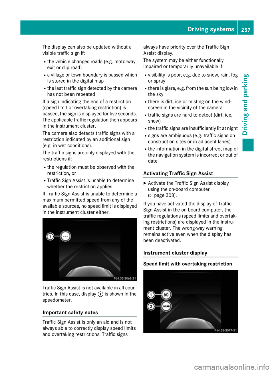
in the instrument cluster either. Traffic Sign Assist is not available in all coun-
tries. In this case, display :is shown in the
speedometer.
Important safety notes Traffic Sign Assist is only an aid and is not
always able to correctly display speed limits
and overtaking restrictions. Traffic signs always have priority over the Traffic Sign
Assist display.
The system may be either functionally
impaired or temporarily unavailable if:
R visibility is poor, e.g. due to snow, rain, fog
or spray
R there is glare, e.g. from the sun being low in
the sky
R there is dirt, ice or misting on the wind-
screen in the vicinity of the camera
R traffic signs are hard to detect (dirt, ice,
snow)
R the traffic signs are insufficiently lit at night
R signs are ambiguous (e.g. traffic signs on
construction sites or in adjacent lanes)
R the information in the digital street map of
the navigation system is incorrect or out of
date
Activating Traffic Sign Assist X
Activate the Traffic Sign Assist display
using the on-board computer
(Y page 308).
If you have activated the display of Traffic
Sign Assist in the on-board computer, the
traffic regulations (speed limits and overtak-
ing restrictions) are displayed in the instru-
ment cluster. The wrong-way warning
remains active even when the display has
been deactivated.
Instrument cluster display Speed limit with overtaking restriction Driving systems
257Driving and parking Z
Page 261 of 489
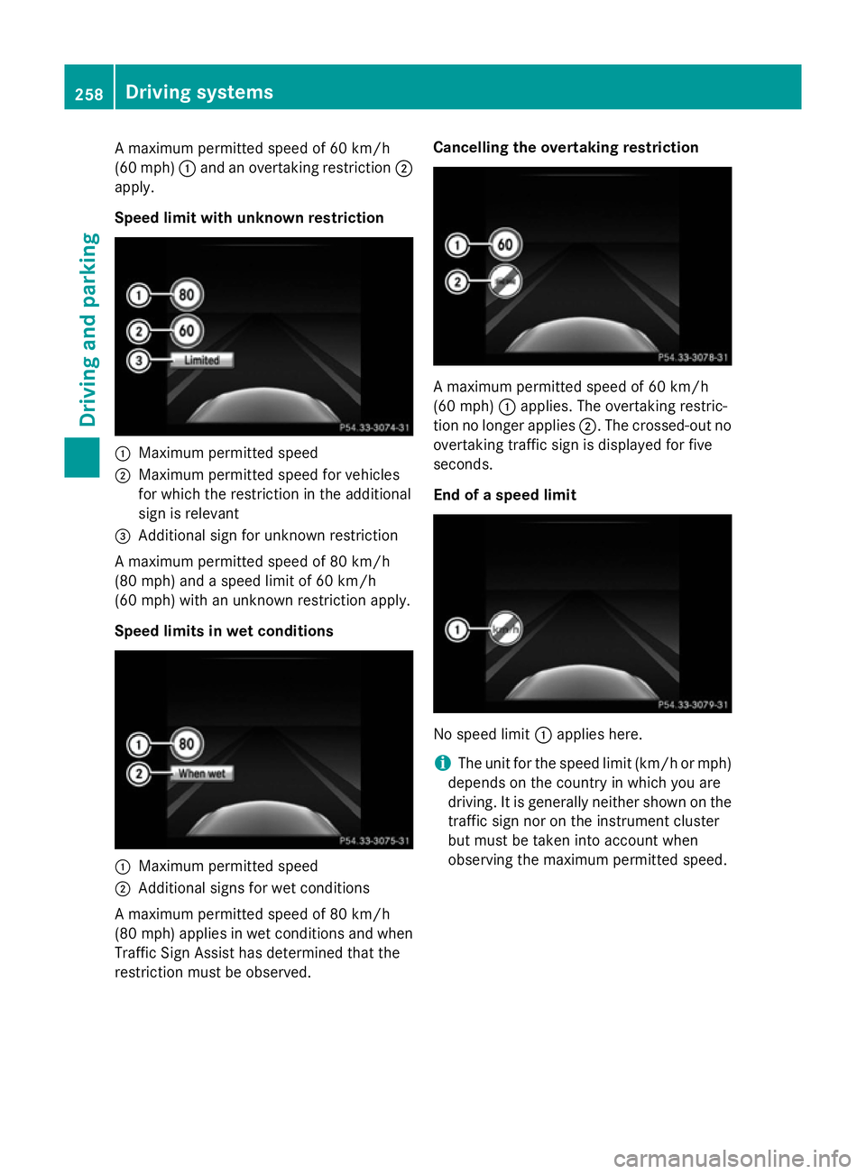
A maximum permitted speed of 60 km/h
(60 mph) :and an overtaking restriction ;
apply.
Speed limit with unknown restriction :
Maximum permitted speed
; Maximum permitted speed for vehicles
for which the restriction in the additional
sign is relevant
= Additional sign for unknown restriction
A maximum permitted speed of 80 km/h
(80 mph) and a speed limit of 60 km/h
(60 mph) with an unknown restriction apply.
Speed limits in wet conditions :
Maximum permitted speed
; Additional signs for wet conditions
A maximum permitted speed of 80 km/h
(80 mph) applies in wet conditions and when
Traffic Sign Assist has determined that the
restriction must be observed. Cancelling the overtaking restriction
A maximum permitted speed of 60 km/h
(60 mph)
:applies. The overtaking restric-
tion no longer applies ;. The crossed-out no
overtaking traffic sign is displayed for five
seconds.
End of a speed limit No speed limit
:applies here.
i The unit for the speed limit (km/h or mph)
depends on the country in which you are
driving. It is generally neither shown on the
traffic sign nor on the instrument cluster
but must be taken into account when
observing the maximum permitted speed. 258
Driving systemsDriving an
d parking
Page 262 of 489
No entry (wrong-way warning)
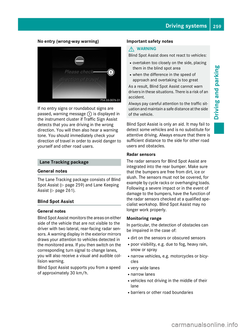
If no entry signs or roundabout signs are
passed, warning message :is displayed in
the instrument cluster if Traffic Sign Assist
detects that you are driving in the wrong
direction. You will then also hear a warning
tone. You should immediately check your
direction of travel in order to avoid danger to yourself and other road users. Lane Tracking package
General notes The Lane Tracking package consists of Blind
Spot Assist (Y
page 259) and Lane Keeping
Assist (Y page 261).
Blind Spot Assist General notes
Blind Spot Assist monitors the areas on either
side of the vehicle that are not visible to the
driver with two lateral, rear-facing radar sen-
sors. A warning display in the exterior mirrors draws your attention to vehicles detected in
the monitored area. If you then switch on the corresponding turn signal to change lanes,
you will also receive a visual and audible col-
lision warning.
Blind Spot Assist supports you from a speed
of approximately 30 km/h. Important safety notes G
WARNING
Blind Spot Assist does not react to vehicles:
R overtaken too closely on the side, placing
them in the blind spot area
R when the difference in the speed of
approach and overtaking is too great
As a result, Blind Spot Assist cannot warn
drivers in these situations. There is a risk of an accident.
Always pay careful attention to the traffic sit- uation and maintain a safe distance at the side
of the vehicle.
Blind Spot Assist is only an aid. It may fail to
detect some vehicles and is no substitute for
attentive driving. Always ensure that there is
sufficient distance to the side for other road
users and obstacles.
Radar sensors
The radar sensors for Blind Spot Assist are
integrated into the rear bumper. Make sure
that the bumpers are free from dirt, ice or
slush. The sensors must not be covered, for
example by cycle racks or overhanging loads.
Following a severe impact or in the event of
damage to the bumpers, have the function of the radar sensors checked at a qualified spe-
cialist workshop. Blind Spot Assist may no
longer work properly.
Monitoring range
In particular, the detection of obstacles can
be impaired in the case of:
R dirt on the sensors or obscured sensors
R poor visibility, e.g. due to fog, heavy rain,
snow or spray
R narrow vehicles, e.g. motorcycles or bicy-
cles
R very wide lanes
R narrow lanes
R vehicles not driving in the middle of their
lane
R barriers or other road boundaries Driving systems
259Driving and parking Z
Page 275 of 489
Instrument cluster
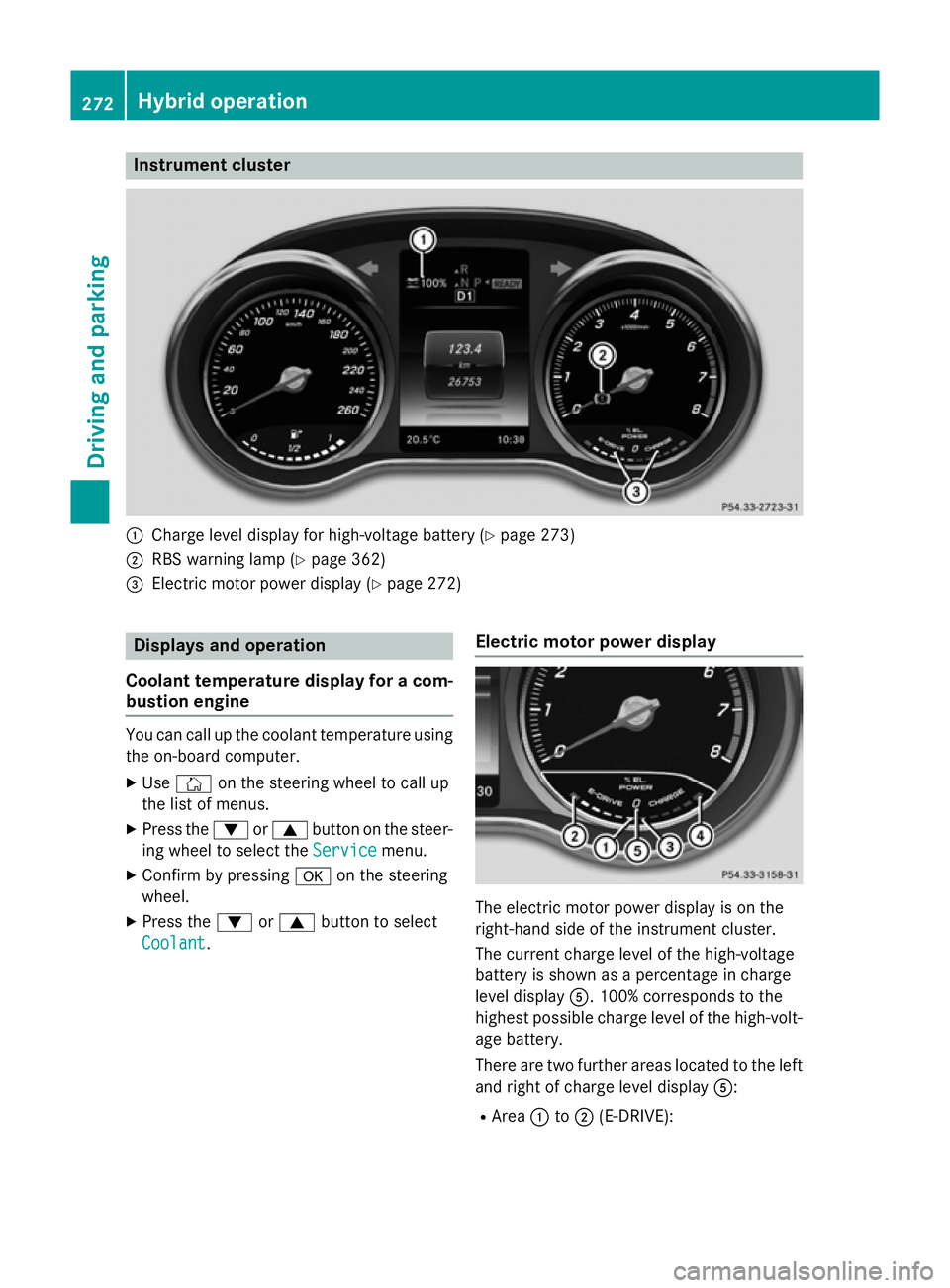
:
Charge level display for high-voltage battery (Y page 273)
; RBS warning lamp (Y page 362)
= Electric motor power display (Y page 272)Displays and operation
Coolant temperature display for a com- bustion engine You can call up the coolant temperature using
the on-board computer.
X Use Ñ on the steering wheel to call up
the list of menus.
X Press the :or9 button on the steer-
ing wheel to select the Service
Servicemenu.
X Confirm by pressing aon the steering
wheel.
X Press the :or9 button to select
Coolant
Coolant. Electric motor power display The electric motor power display is on the
right-hand side of the instrument cluster.
The current charge level of the high-voltage
battery is shown as a percentage in charge
level display
A. 100% corresponds to the
highest possible charge level of the high-volt- age battery.
There are two further areas located to the left
and right of charge level display A:
R Area :to; (E-DRIVE): 272
Hybrid operationDriving and pa
rking
Page 284 of 489
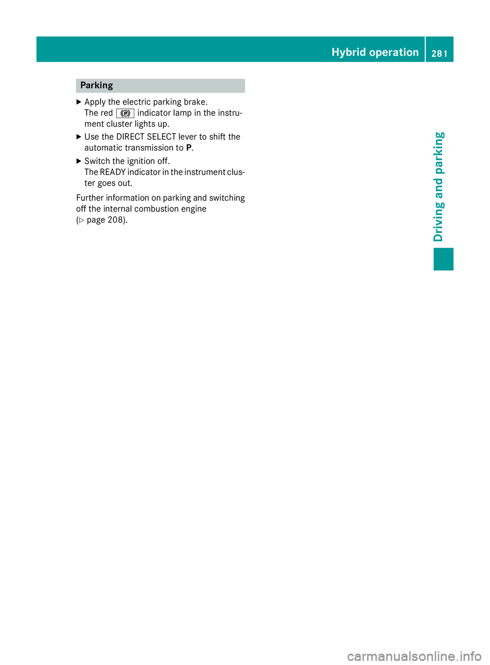
Parking
X Apply the electric parking brake.
The red !indicator lamp in the instru-
ment cluster lights up.
X Use the DIRECT SELECT lever to shift the
automatic transmission to P.
X Switch the ignition off.
The READY indicator in the instrument clus-
ter goes out.
Further information on parking and switching off the internal combustion engine
(Y page 208). Hybrid operation
281Driving and parking Z
Page 285 of 489
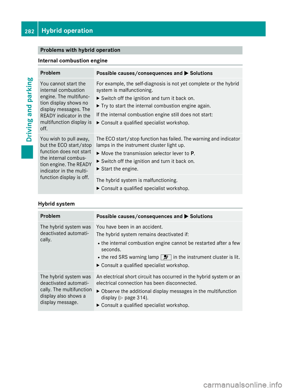
Problems with hybrid operation
Internal combustion engine Problem
Possible causes/consequences and
M
MSolutions You cannot start the
internal combustion
engine. The multifunc-
tion display shows no
display messages. The
READY indicator in the
multifunction display is
off. For example, the self-diagnosis is not yet complete or the hybrid
system is malfunctioning.
X Switch off the ignition and turn it back on.
X Try to start the internal combustion engine again.
If the internal combustion engine still does not start: X Consult a qualified specialist workshop. You wish to pull away,
but the ECO start/stop
function does not start
the internal combus-
tion engine. The READY
indicator in the multi-
function display is off. The ECO start/stop function has failed. The warning and indicator
lamps in the instrument cluster light up.
X Move the transmission selector lever to P.
X Switch off the ignition and turn it back on.
X Start the engine. The hybrid system is malfunctioning.
X Consult a qualified specialist workshop. Hybrid system
Problem
Possible causes/consequences and
M MSolutions The hybrid system was
deactivated automati-
cally. You have been in an accident.
The hybrid system remains deactivated if:
R the internal combustion engine cannot be restarted after a few
seconds.
R the red SRS warning lamp 6in the instrument cluster is lit.
X Consult a qualified specialist workshop. The hybrid system was
deactivated automati-
cally. The multifunction
display also shows a
display message. An electrical short circuit has occurred in the hybrid system or an
electrical connection has been disconnected.
X Observe the additional display messages in the multifunction
display (Y page 314).
X Consult a qualified specialist workshop. 282
Hybrid operationDriving and parking
Page 294 of 489
Useful information
............................292
Important safety notes .....................292
Displays and operation .....................292
Menus and submenus ......................297
Display messages ............................. 314
Warning and indicator lamps in the instrument cluster ............................351 291On-board computer and displays
Page 295 of 489
Useful information
i This Owner's Manual describes all mod-
els, series and optional equipment for your
vehicle that were available at the time of
going to press. National variations are pos- sible. Note that your vehicle may not be
equipped with all of the functions descri-
bed. This is also the case for systems and
functions relevant to safety.
i Read the information on qualified special-
ist workshops: (Y page 27). Important safety notes
G
WARNING
Operating the integrated information systems and communications equipment in the vehicle
while driving will distract you from traffic con-
ditions. You could then lose control of the
vehicle. There is a risk of an accident.
Only operate these devices if road traffic con-
ditions permit. If you are unsure about the
surrounding conditions, pull over to a safe
location and make entries only while the vehi-
cle is stationary.
You must observe the legal requirements for
the country in which you are currently driving when operating the on-board computer. G
WARNING
If the instrument cluster has failed or mal-
functioned, you may not recognise function
restrictions relevant to safety. The operating
safety of your vehicle may be impaired. There is a risk of an accident.
Drive on carefully. Have the vehicle checked
at a qualified specialist workshop immedi-
ately.
The on-board computer only shows messages
or warnings from certain systems in the mul- tifunction display. You should therefore make
sure your vehicle is operating safely at all times. Otherwise, a vehicle that is not oper-
ating safely may cause an accident.
If the operating safety of your vehicle is
impaired, park the vehicle safely as soon as
possible. Contact a qualified specialist work-
shop.
For an overview, see the instrument cluster
illustration (Y
page 34). Displays and operation
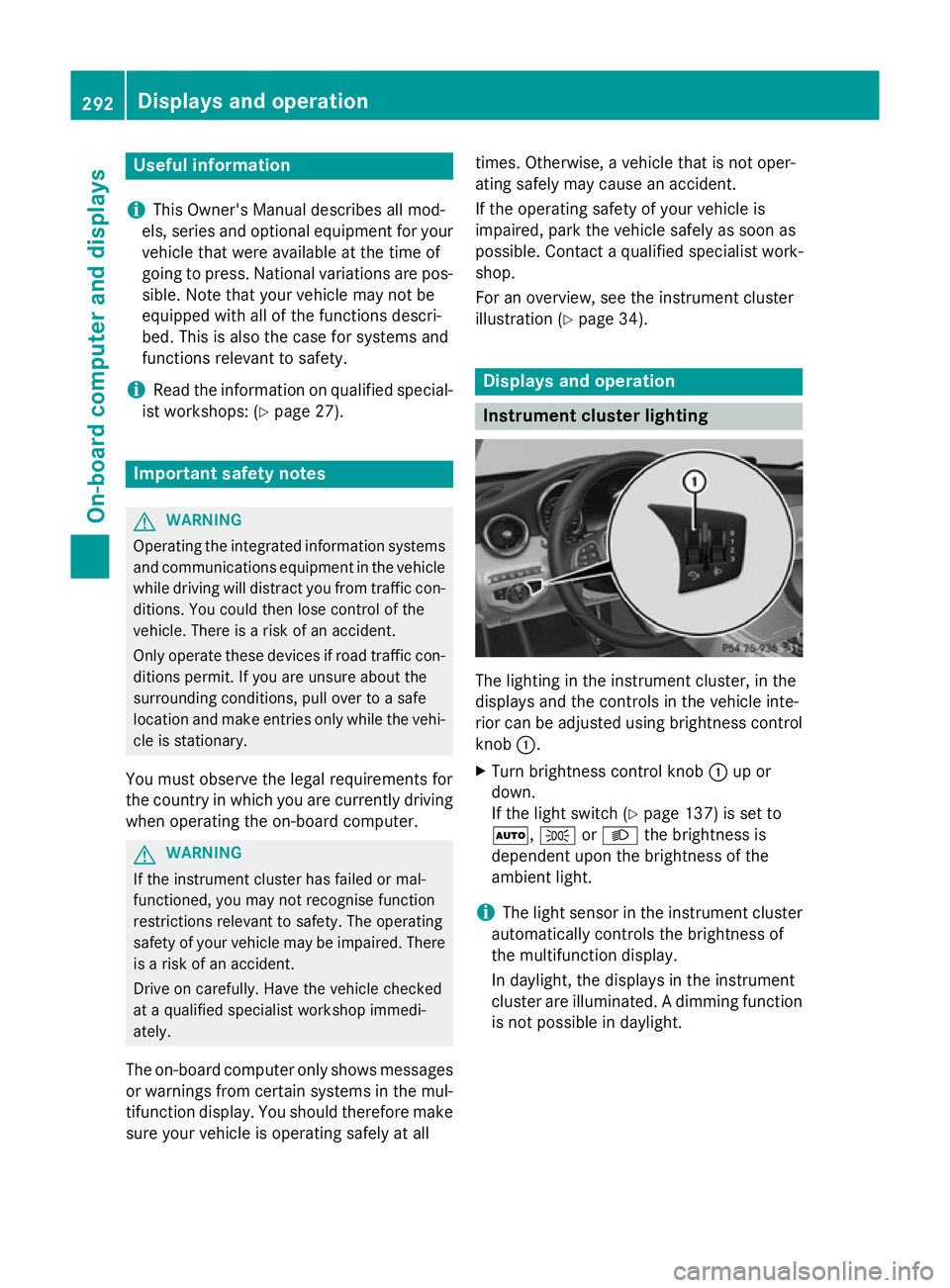
Instrument cluster lighting
The lighting in the instrument cluster, in the
displays and the controls in the vehicle inte-
rior can be adjusted using brightness control
knob :.
X Turn brightness control knob :up or
down.
If the light switch (Y page 137) is set to
Ã, TorL the brightness is
dependent upon the brightness of the
ambient light.
i The light sensor in the instrument cluster
automatically controls the brightness of
the multifunction display.
In daylight, the displays in the instrument
cluster are illuminated. A dimming function
is not possible in daylight. 292
Displays and operationOn-board computer and displays
Page 296 of 489
Speedometer with segments
The segments in the speedometer indicate
which speed range is available.
R Cruise control activated (Y page 216):
The segments light up from the stored
speed to the maximum speed.
R Variable SPEEDTRONIC activated
(Y page 219):
The segments light up from the start of the
scale to the selected limit speed.
R DISTRONIC PLUS activated (Y page 222):
One or two segments in the set speed
range light up.
R DISTRONIC PLUS detects a vehicle in front:
The segments between the speed of the
vehicle in front and the stored speed light
up. Rev counter
! Do not drive in the overrevving range.
Doing so will damage the engine.
The red band in the rev counter indicates the engine's overrevving range.
The fuel supply is interrupted to protect the
engine when the red band is reached. Outside temperature display
You should pay special attention to road con-
ditions when temperatures are around the
freezing point.
Bear in mind that the outside temperature
display indicates the temperature measured
and does not record the road temperature.
The outside temperature display is in the mul- tifunction display (Y page 295).
Changes in the outside temperature are dis-
played after a short delay. Coolant temperature gauge
G
WARNING
If you open the bonnet while the engine is
overheating or while there is a fire in the
engine compartment, you could come into
contact with hot gases or other leaking ser-
vice products. There is a danger of injury.
Allow an overheating engine to cool down
before opening the bonnet. If there is a fire in the engine compartment, leave the bonnet
closed and notify the fire brigade.
The analogue coolant temperature gauge is in
the instrument cluster on the right-hand side (Y page 34).
In the on-board computer in the Service Service
menu there is a digital coolant temperature
gauge (Y page 307).
Under normal operating conditions and with
the specified coolant level, the coolant tem-
perature may rise to 120 †.
At high outside temperatures and when driv-
ing uphill, the coolant temperature may rise
to the end of the scale. Displays and operation
293On-board computer and displays Z
Page 297 of 489
Operating the on-board computer
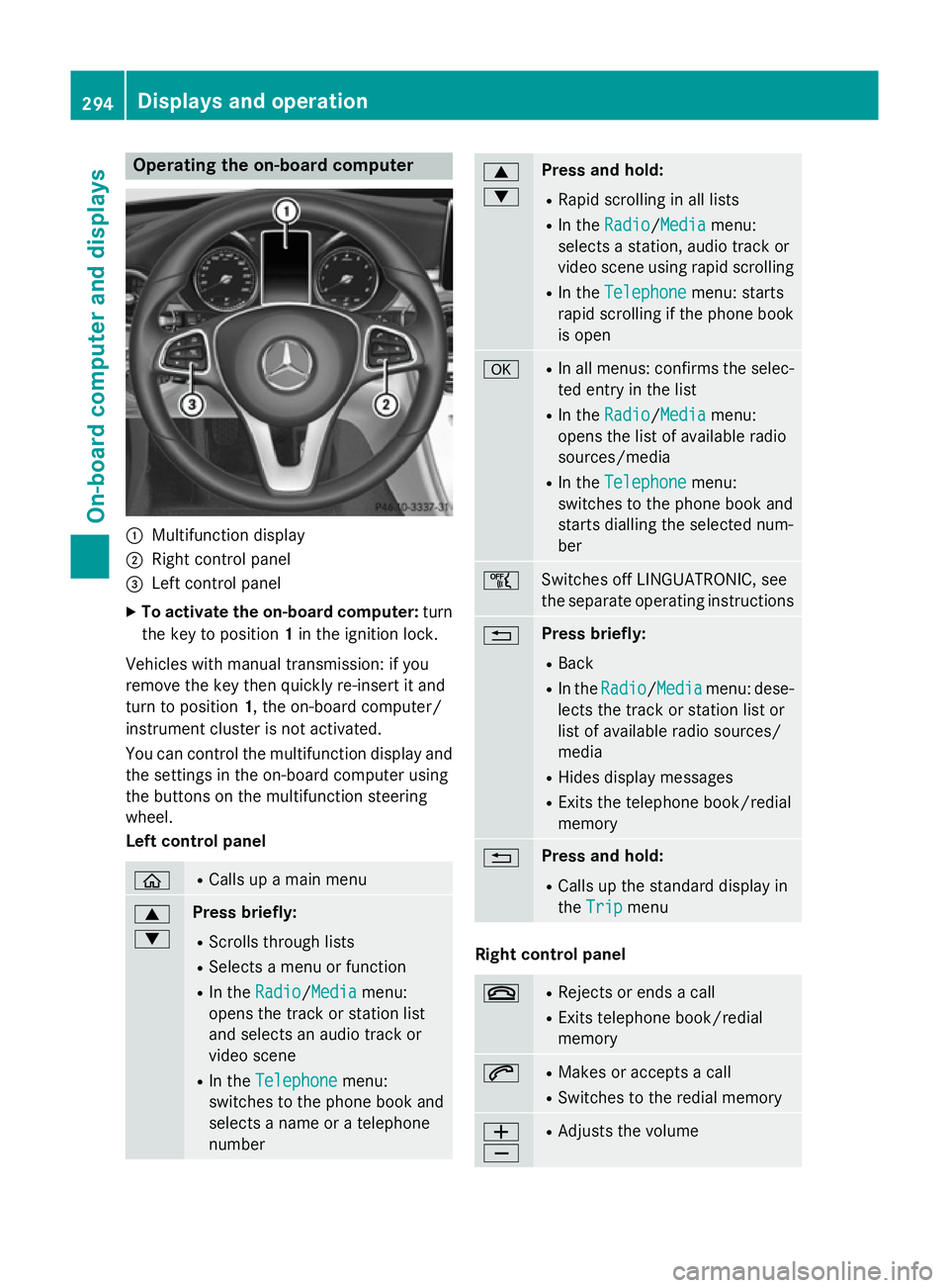
:
Multifunction display
; Right control panel
= Left control panel
X To activate the on-board computer: turn
the key to position 1in the ignition lock.
Vehicles with manual transmission: if you
remove the key then quickly re-insert it and
turn to position 1, the on-board computer/
instrument cluster is not activated.
You can control the multifunction display and
the settings in the on-board computer using
the buttons on the multifunction steering
wheel.
Left control panel ò R
Calls up a main menu 9
: Press briefly:
R Scrolls through lists
R Selects a menu or function
R In the Radio Radio/Media Mediamenu:
opens the track or station list
and selects an audio track or
video scene
R In the Telephone Telephone menu:
switches to the phone book and
selects a name or a telephone
number 9
: Press and hold:
R Rapid scrolling in all lists
R In the Radio Radio/ Media
Media menu:
selects a station, audio track or
video scene using rapid scrolling
R In the Telephone Telephone menu: starts
rapid scrolling if the phone book is open a R
In all menus: confirms the selec-
ted entry in the list
R In the Radio
Radio/Media Mediamenu:
opens the list of available radio
sources/media
R In the Telephone Telephone menu:
switches to the phone book and
starts dialling the selected num-
ber ñ
Switches off LINGUATRONIC, see
the separate operating instructions
% Press briefly:
R Back
R In the Radio Radio/Media Mediamenu: dese-
lects the track or station list or
list of available radio sources/
media
R Hides display messages
R Exits the telephone book/redial
memory % Press and hold:
R Calls up the standard display in
the Trip Trip menu Right control panel
~ R
Rejects or ends a call
R Exits telephone book/redial
memory 6 R
Makes or accepts a call
R Switches to the redial memory W
X R
Adjusts the volume 294
Displays and operationOn-board computer and displays