boot MERCEDES-BENZ C-CLASS SALOON 2014 Workshop Manual
[x] Cancel search | Manufacturer: MERCEDES-BENZ, Model Year: 2014, Model line: C-CLASS SALOON, Model: MERCEDES-BENZ C-CLASS SALOON 2014Pages: 489, PDF Size: 14.88 MB
Page 443 of 489
must be positioned vertically, directly under
the jacking point of the vehicle.
Observe the following when raising the
vehicle: R to raise the vehicle, only use the vehicle-
specific jack that has been tested and
approved by Mercedes-Benz. If the jack is
used incorrectly, it could tip over while the vehicle is raised.
R the jack is designed only to raise and hold
the vehicle for a short time while a wheel
is being changed. It is not suitable for per-
forming maintenance work under the vehi- cle.
R avoid changing the wheel on uphill and
downhill slopes.
R before raising the vehicle, secure it from
rolling away by applying the parking brake
and positioning wheel chocks. Do not
release the parking brake while the vehicle
is raised.
R the jack must be placed on a firm, flat and
non-slip surface. On a loose surface, a
large, flat load-bearing underlay must be
used. On a slippery surface, a non-slip
underlay must be used, e.g. rubber mats.
R do not use wooden blocks or similar
objects as a jack underlay. Otherwise, the
jack will not be able to achieve its load-
bearing capacity due to the restricted
height.
R make sure that the distance between the
underside of the tyres and the ground does not exceed 3 cm.
R never place your hands or feet under the
raised vehicle.
R do not lie under the vehicle.
R do not start the engine when the vehicle is
raised.
R do not open or close a door or the boot lid
when the vehicle is raised.
R make sure that no persons are present in
the vehicle when the vehicle is raised. Vehicles with steel wheels and wheel
trim:
the wheel trim covers the wheel bolts.
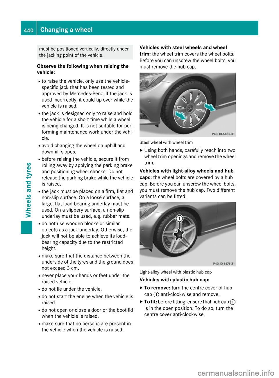
Before you can unscrew the wheel bolts, you must remove the hub cap. Steel wheel with wheel trim
X
Using both hands, carefully reach into two
wheel trim openings and remove the wheel trim.
Vehicles with light-alloy wheels and hub
caps: the wheel bolts are covered by a hub
cap. Before you can unscrew the wheel bolts, you must remove the hub cap. Two different
variants can be fitted. Light-alloy wheel with plastic hub cap
Vehicles with plastic hub cap:
X To remove: turn the centre cover of hub
cap :anti-clockwise and remove.
X To fit: before fitting, ensure that hub cap :
is in the open position. To do so, turn the
centre cover anti-clockwise. 440
Changing a wheelWheels and tyres
Page 446 of 489
approved for Mercedes-Benz vehicles and the
respective wheel. X
Clean the wheel and wheel hub contact
surfaces.
X Slide the wheel to be mounted onto the
centring pin and push it on.
X Tighten the wheel bolts until they are fin-
ger-tight.
X Unscrew the centring pin.
X Tighten the last wheel bolt until it is finger-
tight.
X Vehicles with a collapsible emergency
spare wheel: inflate the collapsible emer-
gency spare wheel (Y page 462).
Only then lower the vehicle.
Lowering the vehicle G
WARNING
The wheels could work loose if the wheel nuts and bolts are not tightened to the specified
tightening torque. There is a risk of accident.
Have the tightening torque immediately
checked at a qualified specialist workshop
after a wheel is changed.
! Vehicles with a collapsible emergency
spare wheel: Inflate the collapsible emer-
gency spare wheel using the tyre inflation
compressor before lowering the vehicle.
The rim could otherwise be damaged. X
Turn the crank of the jack anti-clockwise
until the vehicle is once again standing
firmly on the ground.
X Place the jack to one side.
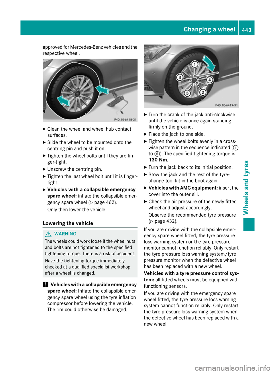
X Tighten the wheel bolts evenly in a cross-
wise pattern in the sequence indicated ( :
to A). The specified tightening torque is
130 Nm.
X Turn the jack back to its initial position.
X Stow the jack and the rest of the tyre-
change tool kit in the boot again.
X Vehicles with AMG equipment: insert the
cover into the outer sill.
X Check the air pressure of the newly fitted
wheel and adjust accordingly.
Observe the recommended tyre pressure
(Y page 432).
If you are driving with the collapsible emer-
gency spare wheel fitted, the tyre pressure
loss warning system or the tyre pressure
monitor cannot function reliably. Only restart
the tyre pressure loss warning system/tyre
pressure monitor when the defective wheel
has been replaced with a new wheel.
Vehicles with a tyre pressure control sys-
tem: all fitted wheels must be equipped with
functioning sensors.
If you are driving with the emergency spare
wheel fitted, the tyre pressure loss warning
system cannot function reliably. Only restart
the tyre pressure loss warning system when
the defective wheel has been replaced with a
new wheel. Changing a wheel
443Wheels and tyres Z
Page 465 of 489
An emergency spare wheel may also be fitted
against the direction of rotation. Observe the
time restriction on use as well as the speed
limitation specified on the emergency spare
wheel.
Replace the tyres after six years at the latest,
regardless of wear. This also applies to the
emergency spare wheel.
If you are driving with the collapsible emer-
gency spare wheel fitted, the tyre pressure
loss warning system or the tyre pressure
monitor cannot function reliably. Only restart the tyre pressure loss warning system/tyre
pressure monitor when the defective wheel
has been replaced with a new wheel.
Vehicles with tyre pressure monitor: after
mounting an emergency spare wheel, the sys- tem may still display the tyre pressure of the
removed wheel for a few minutes. The value
displayed for the mounted emergency spare
wheel is not the same as the current tyre
pressure of the emergency spare wheel.
If you are driving with the emergency spare
wheel fitted, the tyre pressure loss warning
system cannot function reliably. Only restart
the tyre pressure loss warning system when
the defective wheel has been replaced with a
new wheel. Removing the emergency spare wheel
The emergency spare wheel is secured in the
emergency spare wheel bag in the boot.
X Open the boot.
X Detach the fastening straps.
X Unhook retaining spring hooks of fastening
straps from the retainers.
X Remove the emergency spare wheel bag
with the emergency spare wheel.
X Open the bag and remove the emergency
spare wheel.
Observe the instructions and safety notes in
the "Fitting a wheel" section (Y page 438). Inflating the collapsible emergency
spare wheel
! Inflate the collapsible emergency spare
wheel using the tyre inflation compressor
before lowering the vehicle. The wheel rim
could otherwise be damaged.
! Do not operate the tyre inflation com-
pressor for longer than eight minutes at a
time without a break. It may otherwise
overheat.
The tyre inflation compressor can be oper-
ated again once it has cooled down. X
Mount the collapsible emergency spare
wheel as described (Y page 437).
The collapsible emergency spare wheel
must be mounted before it is inflated.
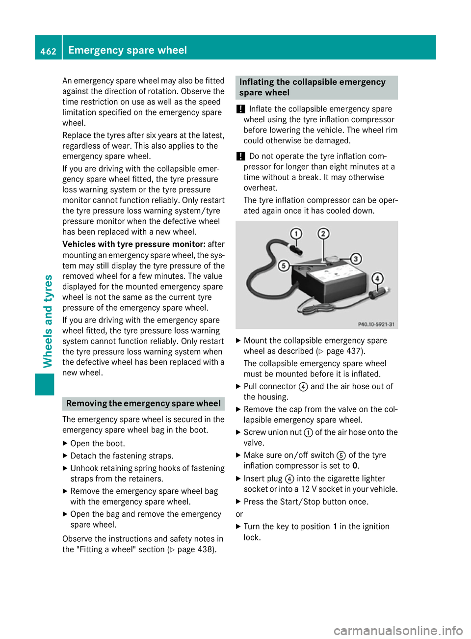
X Pull connector ?and the air hose out of
the housing.
X Remove the cap from the valve on the col-
lapsible emergency spare wheel.
X Screw union nut :of the air hose onto the
valve.
X Make sure on/off switch Aof the tyre
inflation compressor is set to 0.
X Insert plug ?into the cigarette lighter
socket or into a 12 V socket in your vehicle.
X Press the Start/Stop button once.
or X Turn the key to position 1in the ignition
lock. 462
Emergency spare wheelWheels and tyres
Page 470 of 489
sion surrounding the possible health risk
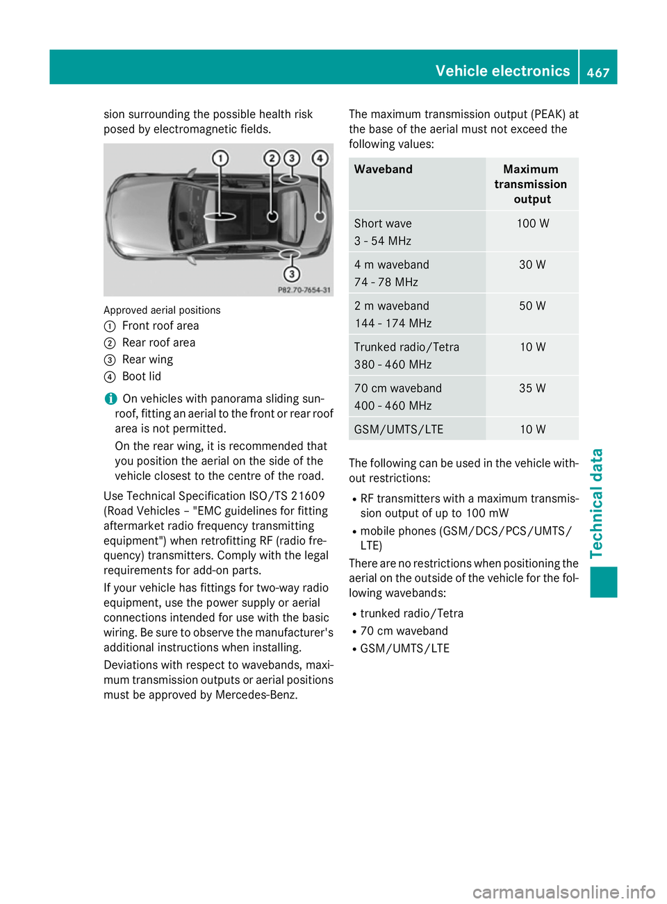
posed by electromagnetic fields. Approved aerial positions
:
Front roof area
; Rear roof area
= Rear wing
? Boot lid
i On vehicles with panorama sliding sun-
roof, fitting an aerial to the front or rear roof
area is not permitted.
On the rear wing, it is recommended that
you position the aerial on the side of the
vehicle closest to the centre of the road.
Use Technical Specification ISO/TS 21609
(Road Vehicles – "EMC guidelines for fitting
aftermarket radio frequency transmitting
equipment") when retrofitting RF (radio fre-
quency) transmitters. Comply with the legal
requirements for add-on parts.
If your vehicle has fittings for two-way radio
equipment, use the power supply or aerial
connections intended for use with the basic
wiring. Be sure to observe the manufacturer's additional instructions when installing.
Deviations with respect to wavebands, maxi-
mum transmission outputs or aerial positions must be approved by Mercedes-Benz. The maximum transmission output (PEAK) at
the base of the aerial must not exceed the
following values: Waveband Maximum
transmission output Short wave
3 - 54 MHz 100 W
4 m waveband
74 - 78 MHz 30 W
2 m waveband
144 - 174 MHz 50 W
Trunked radio/Tetra
380 - 460 MHz 10 W
70 cm waveband
400 - 460 MHz 35 W
GSM/UMTS/LTE 10 W
The following can be used in the vehicle with-
out restrictions:
R RF transmitters with a maximum transmis-
sion output of up to 100 mW
R mobile phones (GSM/DCS/PCS/UMTS/
LTE)
There are no restrictions when positioning the aerial on the outside of the vehicle for the fol-
lowing wavebands:
R trunked radio/Tetra
R 70 cm waveband
R GSM/UMTS/LTE Vehicle electronics
467Technical data Z
Page 480 of 489
Model
:
:
Opening height C 180 BlueEFFI-
CIENCY Edition
1763 mm
C 250 BlueTEC
4MATIC
1774 mm
C 300 BlueTEC Hybrid
1768 mm
All other models
1763 mm
All models
Vehicle length
4686 mm
Vehicle width including
exterior mirrors
2020 mm
Vehicle width excluding
exterior mirrors
1810 mm
Wheelbase
2840 mm
Maximum roof load
75 kg
Maximum boot load
100 kg
Model Vehicle
height C 250 BlueTEC 4MATIC
1452 mm
C 300 BlueTEC Hybrid
1447 mm
All other models
1442 mm
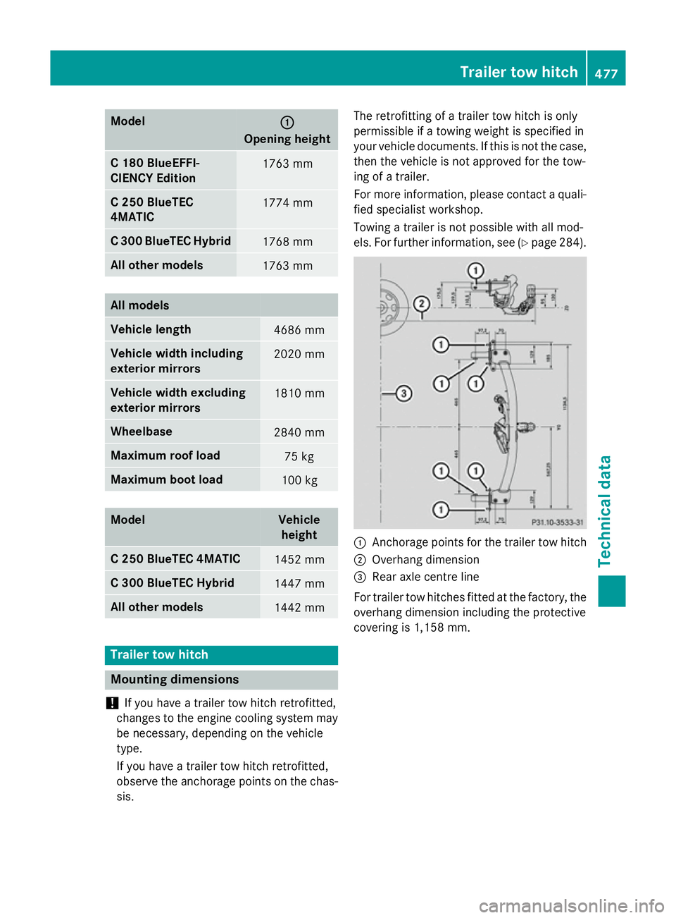
Trailer tow hitch
Mounting dimensions
! If you have a trailer tow hitch retrofitted,
changes to the engine cooling system may
be necessary, depending on the vehicle
type.
If you have a trailer tow hitch retrofitted,
observe the anchorage points on the chas- sis. The retrofitting of a trailer tow hitch is only
permissible if a towing weight is specified in
your vehicle documents. If this is not the case,
then the vehicle is not approved for the tow-
ing of a trailer.
For more information, please contact a quali-
fied specialist workshop.
Towing a trailer is not possible with all mod-
els. For further information, see (Y page 284). :
Anchorage points for the trailer tow hitch
; Overhang dimension
= Rear axle centre line
For trailer tow hitches fitted at the factory, the
overhang dimension including the protective
covering is 1,158 mm. Trailer tow hitch
477Technical data Z