brake MERCEDES-BENZ C-Class SEDAN 2013 W204 Owners Manual
[x] Cancel search | Manufacturer: MERCEDES-BENZ, Model Year: 2013, Model line: C-Class SEDAN, Model: MERCEDES-BENZ C-Class SEDAN 2013 W204Pages: 358, PDF Size: 4.85 MB
Page 306 of 358
X
Close cover 0002of positive terminal 0003after removing the jumper cables.
X Have the battery checked at a qualified specialist workshop.
i Jump-starting is no tconsidered to be a normal operating condition.
i Jumper cables and further information regarding jump-starting can be obtained at any
qualified specialist workshop. Towing and tow-starting
Important safety notes
G
WARNING
You can no longer steer the vehicle if the
steering wheel lock has been engaged. There
is a risk of an accident.
Always switch off the ignition when towing the
vehicle with a tow cable or a tow bar. G
WARNING
If the weight of the vehicle to be towed or tow-
started is greater than the permissible gross
weight of your vehicle:
R the towing eye could detach itself
R the vehicle/trailer combination could
rollover.
There is a risk of an accident.
When towing or tow-starting another vehicle,
its weight should not be greater than the
permissible gross weight of your vehicle.
Information on your vehicle's gross vehicle
weight rating can be found on the vehicle
identification plate (Y page 346).
! If DISTRONIC PLUS or the HOLD function
is activated, the vehicle brakes
automatically in certain situations. To
prevent damage to the vehicle, deactivate
DISTRONIC PLUS and the HOLD function in
the following or other similar situations:
R when towing the vehicle
R in the car wash
! The vehicle can be towed a maximum of
30 miles (50km). The towing speed of
30 mph (50 km/h) must not be exceeded. If the vehicle has to be towed more than
30 miles
(50km), the entire vehicle must be
raised and transported.
! Only secure the tow rope or tow bar at the
towing eyes. Otherwise, the vehicle could
be damaged.
! Do not use the towing eyes for recovery
purposes as this could damage the vehicle.
If in doubt, recover the vehicle with a crane.
! When towing, pull away slowly and
smoothly. If the tractive power is too high,
the vehicles could be damaged.
! Do not tow with sling-type equipment.
This could damage the vehicle.
! On vehicles with KEYLESS-GO, use the
SmartKey instead of the Start/Stop
button. Turn the SmartKey to position 2in
the ignition lock and shift the automatic
transmission to N. Then, turn the SmartKey
back to 0and leave it in the ignition lock.
It is better to have the vehicle transported
than to have it towed.
The automatic transmission must be in
position Nwhen the vehicle is being towed.
The battery must be connected and charged.
Otherwise, you:
R cannot turn the SmartKey to position 2in
the ignition lock
R cannot shift the automatic transmission to
position N
Release the selector lever lock manually to
move it out of position P(Ypage 155).
i Deactivate the automatic locking feature
(Y page 81). You could otherwise be locked
out when pushing or towing the vehicle. 304
Towing and tow-startingBreakdown assistance
Page 307 of 358

Installing/removing the towing eye
Installing the towing eye G
WARNING
The exhaust tail pipe may be very hot .There
is a risk of burns when removing the rear
cover.
Do not touch the exhaust pipe. Take particular
care when removing the rear cover.
X Remove the towing eye from the vehicle
tool kit (Y page 296).
The mountings for the removable towing eyes
are located in the bumpers. They are at the
front and at the rear, behind the covers. X
Press the mark on cover 0002inwards in the
direction of the arrow.
X Take cover 0002off the opening.
X Screw in and tighten the towing eye
clockwise to the stop.
Removing the towing eye X
Unscrew and remove the towing eye.
X Attach cover 0002to the bumper and press
until it engages.
X Place the towing eye in the vehicle tool kit. Towing the vehicle with the rear axle
raised
Only possible for vehicles without
4MATIC.
When towing your vehicle with the rear axle
raised, it is important that you observe the
safety instructions (Y page 304).
! The ignition must be switched off if you
are towing the vehicle with the rear axle
raised. Intervention by ESP ®
could
otherwise damage the brake system.
X Switch on the hazard warning lamps
(Y page 113).
X Turn the SmartKey to position 0in the
ignition lock and remove the SmartKey
from the ignition lock.
X When leaving the vehicle, take the
SmartKey or the KEYLESS-GO key with you. Towing
avehicle with both axles on
the ground
It is importan tthat you observe the safety
instructions when towing away your vehicle
(Y page 304).
X Switch on the hazard warning lamps
(Y page 113).
i When towing with the hazard warning
lamps switched on, use the combination
switch as usual to signal a change of
direction. In this case, only the indicator
lamps for the direction of travel flash. After
resetting the combination switch, the
hazard warning lamp starts flashing again.
X Turn the SmartKey to position 2in the
ignition lock.
X When the vehicle is stationary, depress the
brake pedal and keep it depressed.
X Shift the automatic transmission to
position N.
X Release the brake pedal.
X Release the parking brake. Towing and tow-starting
305Breakdown assistance Z
Page 308 of 358
Transporting the vehicle
The towing eye can be used to pull the vehicle
onto a trailer or transporter for transporting
purposes.
X Turn the SmartKey to position 2in the
ignition lock.
X Move the selector lever to N.
As soon as the vehicle has been loaded:
X Prevent the vehicle fro mrolling away by
applying the parking brake.
X Move the selector lever to position P.
X Turn the SmartKey to position 0in the
ignition lock and remove the SmartKey
from the ignition lock.
X Secure the vehicle.
! Only lash the vehicle down by the wheels
or wheel rims, not by parts of the vehicle
such as axle or steering components.
Otherwise, the vehicle could be damaged. Notes on 4MATIC vehicles
! Vehicles with 4MATIC must not be towed
with either the front or the rear axle raised,
as doing so will damage the transmission.
If the vehicle has transmission damage or
damage to the front or rear axle, have it
transported on a transporter or trailer.
In the event of damage to the electrical
system
If the battery is defective, the automatic
transmission will be locked in position P. To
shift the automatic transmission to position
N, you must provide power to the vehicle's
electrical system in the same way as when
jump-starting (Y page 302).
Have the vehicle transported on a transporter
or trailer. Tow-starting (emergency engine
starting)
! Vehicles with automatic transmission
must not be started by tow-starting. This
could otherwise damage the transmission.
You can find information on "Jump-starting"
at (Y page 302). Fuses
Important safety notes
G
WARNING
If you manipulate or bridge a faulty fuse or if
you replace it with a fuse with a higher
amperage, the electric cables could be
overloaded. This could result in a fire. There
is a risk of an accident and injury.
Always replace faulty fuses with the specified
new fuses having the correc tamperage.
! Only use fuses that have been approved
for Mercedes-Benz vehicles and which
have the correct fuse rating for the system
concerned. Otherwise, components or
systems could be damaged.
The fuses in yourv ehicle serve to close down
faulty circuits. If afuse blows, all the
components on the circuit and their functions
stop operating.
Blown fuses must be replace dwith fuses of
the same rating, which you can recognize by
the color and value. The fuse ratings are listed
in the fuse allocation chart.
If a newly inserted fuse also blows, have the
cause traced and rectified at a qualified
specialist workshop, e.g. an authorized
Mercedes-Ben zCenter. Before changing a fuse
X Secure the vehicle against rolling away
(Y page 158).
X Switch off all electrical consumers. 306
FusesBreakdown assistance
Page 312 of 358
Useful information
i This Operator's Manual describes all
models and all standard and optional
equipment of your vehicle available at the
time of publication of the Operator's
Manual. Country-specific differences are
possible. Please note that your vehicle may
not be equipped with all features
described. This also applies to safety-
related systems and functions.
i Read the information on qualified
specialist workshops: (Y page 25).Important safety notes
G
WARNING
If wheels and tires of the wrong size are used,
the wheel brakes or suspension components
may be damaged. There is arisk of an
accident.
Always replace wheels and tires with those
that fulfill the specifications of the original
part.
When replacing wheels, make sure to use the
correct:
R designation
R model
When replacing tires, make sure to use the
correct:
R designation
R manufacturer
R model G
WARNING
Af lat tire severely impairs the driving,
steering and braking characteristics of the
vehicle. There is a risk of accident.
Tires without run-flat characteristics:
R do not drive with aflat tire.
R immediately replace the flat tire with your
emergency spare wheel or spare wheel, or
consult a qualified specialist workshop. Tires with run-flat characteristics:
R
pay attention to the information and
warning notices on MOExtended tires (tires
with run-flat characteristics).
Accessories that are not approved for your
vehicle by Mercedes-Ben zorare not being
used correctly can impair the operating
safety.
Before purchasing and using non-approved
accessories, visi taqualified specialist
workshop and inquire about:
R suitability
R legal stipulations
R factory recommendations
Information on the dimensions and types of
wheels and tires for your vehicle can be found
in the "Wheel/tire combinations" section
(Y page 338).
Information on air pressure for the tires on
your vehicle can be found:
R on the vehicle's Tire and Loading
Information placard on the B-pillar
R on the tire pressure label on the fuel filler
flap
R in the "Tire pressure" section
Modification work on the brake system and
wheels is not permitted. The use of wheel
spacers or brake dust shields is not
permitted. This invalidates the general
operating permit for the vehicle.
i Further information on wheels and tires
can be obtained at any qualified specialist
workshop. Operation
Information on driving
R If the vehicle is heavily loaded, chec kthe
tire pressures and correct them if
necessary.
R When parking your vehicle, make sure that
the tires do not get deformed by the curb 310
OperationWheels and tires
Page 323 of 358
However, you can also define reference
values manually as described here:
X
Set the tire pressure to the value
recommended for the corresponding
driving situation on the Tire and Loading
Information placard on the B-pillar on the
driver's side (Y page 313).
Additional tire pressure value sfor driving
at high speeds or with heavy loads can be
found in the tire pressure table on the
inside of the fuel filler flap.
X Make sure that the tire pressure is correct
on all four wheels.
X Make sure that the SmartKey is in position
2 in the ignition lock.
X Press the 0002or0005 button on the
steering wheel to select the Servicemenu.
X Press the 0003or0004 button to select
Tire Pressure .
X Press the 000Bbutton.
The multifunction display shows the
current tire pressure for the individual tires
or the Tire pressures will be displayed after driving a few
minutes message.
X Press the 0004button.
The Use Current Pressures as New Reference Values message appears in
the multifunction display.
If you wish to confirm the restart:
X Press the 000Bbutton.
The Tire Press. Monitor Restarted message appears in the multifunction
display.
After driving for a few minutes, the system
checks whether the current tire pressures
are within the specified range. The new tire
pressures are then accepted as reference
values and monitored. If you wish to cancel the restart:
X
Press the 0006button.
The tire pressure values stored at the last
restart will continue to be monitored. Loading the vehicle
Instruction labels for tires and loads
G
WARNING
Overloaded tires can overheat, causing a
blowout. Overloaded tires can also impair the
steering and driving characteristics and lead
to brake failure. There is a risk of accident.
Observe the load rating of the tires. The load
rating must be at least half of the GAWR of
your vehicle. Never overload the tires by
exceeding the maximum load.
Two instruction labels on your vehicle show
the maximum possible load.
(1) The Tire and Loading Information placard is on the B-pillar on the driver's side. The
Tire and Loading Information placard
shows the maximum permissible number
of occupants and the maximum
permissible vehicle load. It also contains
details of the tire sizes and
corresponding pressures for tires
mounted at the factory.
(2) The vehicle identification plate is on the B-pillar on the driver's side. The vehicle
identification plate informs you of the
gross vehicle weight rating. It is made up
of the vehicle weight, all vehicle
occupants, the fuel and the cargo. You
can also find information about the
maximum gross axle weight rating on the
front and rear axle.
The maximum gross axle weight rating is
the maximum weight that can be carried
by one axle (front or rear axle). Never
exceed the maximum load or the
maximum gross axle weight rating for the
front or rear axle. Loading the vehicle
321Wheels and tires Z
Page 335 of 358
Aspect ratio
Relationship between tire height and tire
width in percent. Tire pressure
This is pressure inside the tire applying an
outward force to each square inch of the tire's
surface. The tire pressure is specified in
pounds per square inch (psi), in kilopascal
(kPa) or in bar. The tire pressure should only
be corrected when the tires are cold. Tire pressure of cold tires
The tires are cold:
R if the vehicle has been parked without
direct sunligh tonthe tires for at least three
hours and
R if the vehicle has not been driven further
than 1 mile (1.6 km) Tread
The part of the tire that comes into contact
with the road. Bead
The tire bead ensures that the tire sits
securely on the wheel. There are several steel
wires in the bead to prevent the tire from
coming loose from the wheel rim. Sidewall
The part of the tire between the tread and the
bead. Weight of optional extras
The combined weight of those optional extras
that weigh more than the replaced standard
parts and more than 2.3 kg (5 lbs). These optional extras, such as high-performance
brakes, level control, a roof rack or a high-
performance battery, are not included in the
curb weight and the weight of the
accessories.
TIN (Tire Identification Number)
This is a unique identifier which can be used
by a tire manufacturer to identify tires, for
example for a product recall, and thus identify
the purchasers. The TIN is made up of the
manufacturer's identity code, tire size, tire
type code and the manufacturing date. Load bearing index
The load bearing index (also load index) is a
code that contains the maximum load bearing
capacity of a tire. Traction
Traction is the result of friction between the
tires and the road surface. Treadwear indicators
Narrow bars (tread wear bars) that are
distributed over the tire tread. If the tire tread
is level with the bars, the wear limit of 0008in
(1.6 mm) has been reached. Occupant distribution
The distribution of occupants in a vehicle at
their designated seating positions. Total load limit
Nominal load and luggage load plus 68 kg
(150 lbs) multiplied by the number of seats in
the vehicle. Definition of terms for tires and loading
333Wheels and tires Z
Page 336 of 358
Changing
awheel Flat tire
You can find information on wha tto do in the
event of a flat tire in the "Flat tire" section
(Y page 297).
Information on driving with MOExtended tires
in the event of a flat tire can be found under
"MOExtended tires (tires with run-flat
characteristics" (Y page 297).Rotating the wheels
G
WARNING
Interchanging the front and rear wheels may
severely impair the driving characteristics if
the wheels or tires have different dimensions.
The wheel brakes or suspension components
may also be damaged. There is a risk of
accident.
Rotate front and rear wheels only if the wheels
and tires are of the same dimensions.
! On vehicles equipped with a tire pressure
monitor, electronic components are
located in the wheel.
Tire-mounting tools should not be used
near the valve. This could damage the
electronic components.
Only have tires changed at a qualified
specialist workshop.
Always observe the instructions and safety
notes in the "Mounting awheel" section
(Y page 334).
The wear patterns on the front and rear tires
differ, depending on the operating conditions.
Rotate the wheels before a clear wear pattern
has formed on the tires. Front tires typically
wear more on the shoulders and the rear tires
in the center.
If your vehicle's tire configuration allows, you
can rotate the wheels according to the
intervals in the tire manufacturer's warranty
book in your vehicle documents. If no
warranty book is available, the tires should be rotated every 3,000 to 6,000 miles
(5,000 to
10,000 km), or earlier if tire wear requires. Do
not change the direction of wheel rotation.
Clean the contac tsurface softhe wheel and
the brake disc thoroughly every time a wheel
is rotated. Check the tire pressures.
Information on changing tires and mounting
the spare wheel (Y page 334). Direction of rotation
Tires with a specified direction of rotation
have additional benefits, e.g. if there is a risk
of hydroplaning. You will only gain these
benefits if the correct direction of rotation is
maintained.
An arrow on the sidewall of the tire indicates
its correct direction of rotation. Storing wheels
Store wheels that are not being used in a cool,
dry and preferably dark place. Protect the
tires from oil, grease, gasoline and diesel. Cleaning the wheels
G
WARNING
The water jet from a circular jet nozzle (dirt
blasters) can cause invisible exterior damage
to the tires or chassis components.
Components damaged in this way may fail
unexpectedly. There is a risk of an accident.
Do not use power washers with circular jet
nozzles to clean the vehicle. Have damaged
tires or chassis components replaced
immediately. Mounting
awheel Preparing the vehicle
X Stop the vehicle on solid, non-slippery and
level ground.
X Apply the parking brake. 334
Mounting
awheelWheels and tires
Page 338 of 358

jack must be positioned vertically, directly
under the jacking point of the vehicle.
The following must be observed when raising
the vehicle:
R to raise the vehicle, onl yuse the vehicle-
specific jack that has been tested and
approved by Mercedes-Benz.Ifu sed
incorrectly, the jack could tip over with the
vehicle raised.
R the jack is designed only to raise and hold
the vehicle for a short time while a wheel
is being changed. It is not suited for
performing maintenance work under the
vehicle.
R avoid changing the wheel on uphill and
downhill slopes.
R before raising the vehicle, secure it from
rolling away by applying the parking brake
and inserting wheel chocks. Never
disengage the parking brake while the
vehicle is raised.
R the jack must be placed on a firm, flat and
non-slip surface. On a loose surface, a
large, load-bearing underlay must be used.
On a slippery surface, a non-slip underlay
must be used, e.g. rubber mats.
R do not use wooden blocks or similar
objects as a jack underlay.O therwise, the
jack will not be able to achieve its load-
bearing capacity due to the restricted
height.
R make sure tha tthe distance between the
underside of the tires and the ground does
not exceed 1.2 inches (3 cm).
R never place your hands and feet under the
raised vehicle.
R never lie under the raised vehicle.
R never start the engine when the vehicle is
raised.
R never open or close a door or the trunk lid
when the vehicle is raised.
R make sure that no persons are present in
the vehicle when the vehicle is raised. !
The jack is designed exclusively for
jacking up the vehicle at the jacking points.
Otherwise, your vehicle could be damaged. X
Using lug wrench 0002, loosen the bolts on
the wheel you wish to change by about one
full turn. Do not unscrew the bolts
completely. The jacking points are located just behind the
wheel housings of the front wheels and just
in front of the wheel housings of the rear
wheels (arrows). X
Position jack 0022at jacking point 0003.336
Mounting
awheelWheels and tires
Page 350 of 358
H
Environmental note
Dispose of service products in an
environmentally responsible manner.
Service products include the following:
R Fuels
R Lubricants (e.g .engine oil, transmission oil)
R Coolant
R Brake fluid
R Windshield washe rfluid
R Climate control system refrigerant
Comply with all valid regulations with respect
to handling, storing, and disposing of service
fluids.
Components and service products must be
matched .You should therefor eonly use
products tha thave been tested and approved
by Mercedes-Benz.
Information about tested and approved
products can be obtained from an authorized
Mercedes-Benz Center or on the Internet at
http://bevo.mercedes-benz.co m.
You can recognize service products approved
by Mercedes-Ben zby the following
inscription on the containers:
R MB-Freigabe (e.g. MB-Freigabe 229.51)
R MB Approval (e.g. MB Approval 229.51)
Other designations or recommendations
indicate a level of quality or a specification in
accordance with an MB Sheet number (e.g.
MB 229.5). The yhave no tnecessarily been
approved by Mercedes-Benz. Fuel
Important safety notes G
WARNING
Fuel is highly flammable. If you handle fuel
incorrectly, there is a risk of fire and
explosion.
You must avoid fire, open flames, creating
sparks and smoking. Switch off the engine and, if applicable, the auxiliary heating before
refueling.
G
WARNING
Fuel is poisonous and hazardous to health.
There is a risk of injury.
You must make sure that fuel does not come
into contact with your skin, eyes or clothing
and that it is not swallowed. Do not inhale fuel
vapors. Keep fuel away from children.
If you or others come into contact with fuel,
observe the following:
R Wash away fuel from skin immediately
using soap and water.
R If fuel comes into contact with your eyes,
immediately rinse them thoroughly with
clean water. Seek medical assistance
without delay.
R If fuel is swallowed, seek medical
assistance without delay. Do not induce
vomiting.
R Immediately change out of clothing which
has come into contact with fuel.
Tank capacity Model Total
capacity All models
17.4 US gal
(66.0 l) Model Of which
reserve All models (except
C 63 AMG)
approx
2.1 US gal (8.0 l) C 63 AMG
approx.
3.7 US gal (14.0 l) 348
Service products and filling capacitiesTechnical data
Page 354 of 358
Additives
!
Do no tuse any additives in the engine oil.
This could damage the engine.
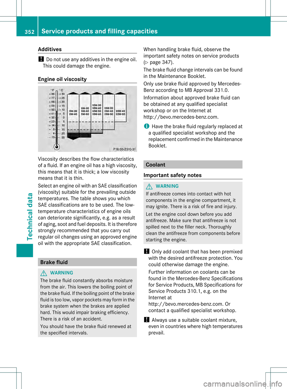
Engine oil viscosity Viscosity describes the flow characteristics
of a fluid. If an engine oil has a high viscosity,
this means that it is thick; a low viscosity
means that it is thin.
Select an engine oil with an SAE classification
(viscosity) suitable for the prevailing outside
temperatures. The table shows you which
SAE classifications are to be used. The low-
temperature characteristics of engine oils
can deteriorate significantly, e.g. as a result
of aging, soot and fuel deposits. It is therefore
strongly recommended that you carry out
regularo
il changes using an approved engine
oil with the appropriate SA Eclassification. Brake fluid
G
WARNING
The brake fluid constantly absorbs moisture
fro mt he air. This lowers the boiling point of
the brake fluid. If the boiling point of the brake
fluid is too low, vapor pockets may form in the
brake system when the brakes are applied
hard. This would impair braking efficiency.
There is a risk of an accident.
You should have the brake fluid renewed at
the specified intervals. When handling brake fluid, observe the
important safety notes on service products
(Y
page 347).
The brake fluid change intervals can be found
in the Maintenance Booklet.
Only use brake fluid approved by Mercedes-
Benz according to MB Approval 331.0.
Information about approved brake fluid can
be obtained at any qualified specialist
workshop or on the Internet at
http://bevo.mercedes-benz.com.
i Have the brake fluid regularly replaced at
a qualified specialist workshop and the
replacement confirmed in the Maintenance
Booklet. Coolant
Important safety notes G
WARNING
If antifreeze comes into contact with hot
components in the engine compartment, it
may ignite. There is a risk of fire and injury.
Let the engine cool down before you add
antifreeze. Make sure that antifreeze is not
spilled next to the filler neck.T horoughly
clean the antifreeze from components before
starting the engine.
! Only add coolant that has been premixed
with the desired antifreezep rotection. You
could otherwise damage the engine.
Further information on coolants can be
found in the Mercedes-Benz Specifications
for Service Products, MB Specifications for
Service Products 310.1, e.g. on the
Internet at
http://bevo.mercedes-benz.com. Or
contact a qualified specialist workshop.
! Always use a suitable coolant mixture,
even in countries where high temperatures
prevail. 352
Service products and filling capacitiesTechnical data