spare wheel MERCEDES-BENZ C230 KOMPRESSOR COUPE 2002 CL203 Owner's Manual
[x] Cancel search | Manufacturer: MERCEDES-BENZ, Model Year: 2002, Model line: C230 KOMPRESSOR COUPE, Model: MERCEDES-BENZ C230 KOMPRESSOR COUPE 2002 CL203Pages: 399
Page 7 of 399

4 Contents
LIGHTING SYSTEM .................... 300
LIGHT SENSOR........................... 302
DOOR............................................ 302
TRUNK OPEN ............................. 303
HOOD ........................................... 303
TELEPHONE – FUNCTION........ 304
TELE AID ..................................... 304
WASHER FLUID.......................... 305
RESTRAINT SYSTEM ................. 306
KEY ............................................... 306
FUEL RESERVE .......................... 307
UNDERVOLTAGE ........................ 307
STEERING WHEEL ADJUST. ..... 308
Practical hintsFirst aid kit...................................... 310
Stowing things in the vehicle ...... 311
Fuses ................................................ 311
Hood ................................................. 315
Automatic transmission
fluid level ................................... 317
Adding engine oil........................... 318
Coolant level ................................... 319Adding coolant ............................ 319
Windshield and headlamp
washer system .......................... 320
Spare wheel, storage
compartment ............................. 321
Vehicle tools and air pump .......... 322
Vehicle jack .................................... 323
Wheels ............................................ 324
Tire replacement........................ 324
Rotating wheels ......................... 325
Spare wheel .................................... 326
Changing wheels ........................... 327
Inflating the collapsible
spare tire ..................................... 333
Storing spare wheel in
wheel well ................................... 334
Tire inflation pressure ................. 335
Battery............................................. 336
Jump starting.................................. 338
Towing the vehicle ........................ 341
Transmission selector lever,
manually unlocking .................. 344
Exterior lamps ............................... 345
Replacing bulbs ......................... 345Changing batteries in the
electronic main key .................. 351
Synchronizing remote
control .......................................... 353
Emergency engine shut-down ..... 353
Fuel filler flap, manual release ... 354
Replacing wiper blade insert ....... 356
Roof rack ......................................... 357
Vehicle careCleaning and care of
the vehicle.................................. 360
Power washer.............................. 361
Tar stains ..................................... 361
Paintwork, painted body
components ................................. 361
Engine cleaning.......................... 362
Vehicle washing ......................... 362
Ornamental moldings................ 363
Headlamps, taillamps,
turn signal lenses ...................... 363
Window cleaning........................ 363
Wiper blade ................................. 363
Page 8 of 399

5 ContentsLight alloy wheels ...................... 364
Instrument cluster ..................... 364
Steering wheel and
gear selector lever ......................364
Cup holder................................... 364
Seat belts ..................................... 365
Headliner and shelf below
rear window ................................ 365
Leather upholstery ..................... 365
Hard plastic trim items ............. 365
Plastic and rubber parts............ 365
Technical dataSpare parts service ........................ 368
Warranty coverage ......................... 368
Identification labels....................... 369
Layout of poly-V-belt drive............ 371
Technical data................................. 373
Fuels, coolants, lubricants etc. -
capacities ................................... 377
Engine oils ...................................... 379
Engine oil additives ....................... 379
Air conditioner refrigerant........... 379
Brake fluid ...................................... 379Premium unleaded gasoline ........ 380
Fuel requirements......................... 380
Gasoline additives ......................... 381
Coolants .......................................... 381
Consumer information ................. 383
Uniform tire quality grading ....... 383
IndexIndex ............................................... 385
Page 278 of 399
275 Driving systems
Te ch n i c a l
data Instruments
and controlsOperationDrivingInstrument
cluster displayPractical hints Car care Index Notes:
The yellow ESP warning lampv in the speedometer
dial comes on with the electronic key in starter switch
position 2. It should go out with the engine running.
If the ESP warning message is displayed, a malfunction
has been detected in the system. Only partial engine
output will be available.
Have the ESP checked at your authorized
Mercedes-Benz Center as soon as possible.
For ESP warning message, see page 288.
With the ABS malfunctioning, the ESP is also switched
off.
Driving the vehicle with varied size tires will cause the
wheels to rotate at different speeds, therefore the ESP
may activate (yellow ESP warning lamp in speedometer
dial comes on). For this reason, all wheels, including the
spare wheel, must have the same tire size. When testing the parking brake on a brake test
dynamometer, the engine must be shut off. Otherwise,
the ESP will immediately be engaged and will apply the
rear wheel brakes.
In winter operation, the maximum effectiveness of the
ESP is only achieved with Mercedes-Benz recommended
M+S rated radial-ply tires and / or snow chains.
Synchronizing ESP
If the power supply was interrupted (battery
disconnected or empty), the ESP warning message may
be displayed with the engine running.
Turn steering wheel completely to the left and then to
the right. The ESP warning message should go out.
Page 312 of 399
309 Contents - Practical hints
Te ch n i c a l
data Instruments
and controlsOperation DrivingInstrument
cluster displayPractical hintsCar care Index
Practical hintsFirst aid kit...................................... 310
Stowing things in the vehicle ...... 311
Fuses ................................................ 311
Hood ................................................. 315
Automatic transmission
fluid level ................................... 317
Adding engine oil........................... 318
Coolant level ................................... 319
Adding coolant............................ 319
Windshield and headlamp
washer system ........................... 320
Spare wheel, storage
compartment.............................. 321Vehicle tools and air pump .......... 322
Vehicle jack .................................... 323
Wheels ............................................ 324
Tire replacement........................ 324
Rotating wheels ......................... 325
Spare wheel .................................... 326
Changing wheels ........................... 327
Inflating the collapsible
spare tire ..................................... 333
Storing spare wheel in
wheel well ................................... 334
Tire inflation pressure ................. 335
Battery............................................. 336
Jump starting.................................. 338Towing the vehicle......................... 341
Transmission selector lever,
manually unlocking ................... 344
Exterior lamps ................................ 345
Replacing bulbs .......................... 345
Changing batteries in the
electronic main key .................. 351
Synchronizing remote
control .......................................... 353
Emergency engine shut-down ..... 353
Fuel filler flap, manual release ... 354
Replacing wiper blade insert ....... 356
Roof rack ......................................... 357
Page 324 of 399
321 Spare wheel
Te ch n i c a l
data Instruments
and controlsOperation DrivingInstrument
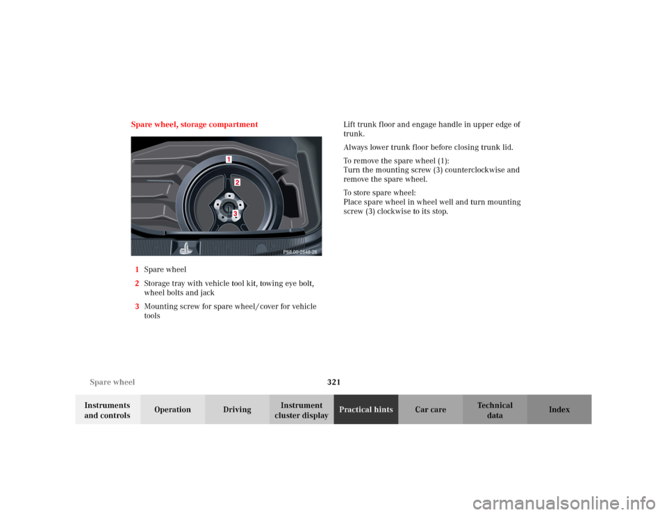
cluster displayPractical hintsCar care Index Spare wheel, storage compartment
1Spare wheel
2Storage tray with vehicle tool kit, towing eye bolt,
wheel bolts and jack
3Mounting screw for spare wheel / cover for vehicle
toolsLift trunk floor and engage handle in upper edge of
trunk.
Always lower trunk floor before closing trunk lid.
To remove the spare wheel (1):
Turn the mounting screw (3) counterclockwise and
remove the spare wheel.
To store spare wheel:
Place spare wheel in wheel well and turn mounting
screw (3) clockwise to its stop.
P68.00-2648-26
Page 325 of 399
322 Spare wheel
Te ch n i c a l
data Instruments
and controlsOperation DrivingInstrument
cluster displayPractical hintsCar care Index
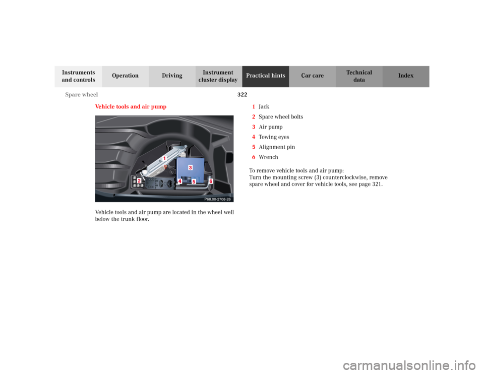
Vehicle tools and air pump
Vehicle tools and air pump are located in the wheel well
below the trunk floor.1Jack
2Spare wheel bolts
3Air pump
4Towin g eyes
5Alignment pin
6Wrench
To remove vehicle tools and air pump:
Turn the mounting screw (3) counterclockwise, remove
spare wheel and cover for vehicle tools, see page 321.
P68.00-2708-26
Page 326 of 399
323 Jack
Te ch n i c a l
data Instruments
and controlsOperation DrivingInstrument
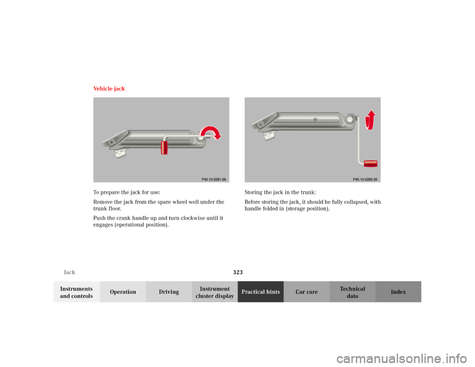
cluster displayPractical hintsCar care Index Ve h i c l e j a c k
To prepare the jack for use:
Remove the jack from the spare wheel well under the
trunk floor.
Push the crank handle up and turn clockwise until it
engages (operational position).Storing the jack in the trunk:
Before storing the jack, it should be fully collapsed, with
handle folded in (storage position).
Page 329 of 399
326 Tires, Wheels
Te ch n i c a l
data Instruments
and controlsOperation DrivingInstrument
cluster displayPractical hintsCar care Index
Spare wheel
Important!
The spare wheel rim size is 4
1/2 Bx15H2 with
inflatable, collapsible tire, size 165 -15 89 P.
You should inflate the spare tire using the supplied air
pump.
In the case of a flat tire, you may temporarily use the
spare wheel, while observing the following restrictions:
•Do not exceed vehicle speed of 50 mph (80 km / h).
•Drive to the nearest tire repair facility to have the
flat tire repaired or replaced as appropriate.
•Do not operate vehicle with more than one
collapsible spare wheel / tire mounted.
For additional information, refer to page 374.
Wa r n i n g !The dimensions of the spare wheel are different
from those of the road wheels. As a result, the
vehicle handling characteristics change when
driving with a mounted spare wheel.The spare wheel should only be used temporarily,
and replaced with a regular road wheel as quick as
possible.
Page 332 of 399
329 Tires, Wheels
Te ch n i c a l
data Instruments
and controlsOperation DrivingInstrument
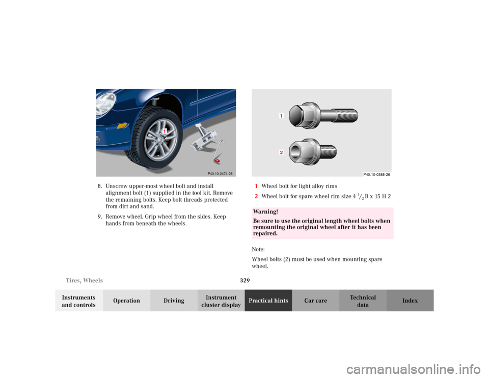
cluster displayPractical hintsCar care Index 8. Unscrew upper-most wheel bolt and install
alignment bolt (1) supplied in the tool kit. Remove
the remaining bolts. Keep bolt threads protected
from dirt and sand.
9. Remove wheel. Grip wheel from the sides. Keep
hands from beneath the wheels.1Wheel bolt for light alloy rims
2Wheel bolt for spare wheel rim size 4
1/2 Bx15H2
Note:
Wheel bolts (2) must be used when mounting spare
wheel.
P40.10-2474-26
Wa r n i n g !
Be sure to use the original length wheel bolts when
remounting the original wheel after it has been
repaired.
P40.10-0388-26
12
Page 335 of 399
332 Tires, Wheels
Te ch n i c a l
data Instruments
and controlsOperation DrivingInstrument
cluster displayPractical hintsCar care Index
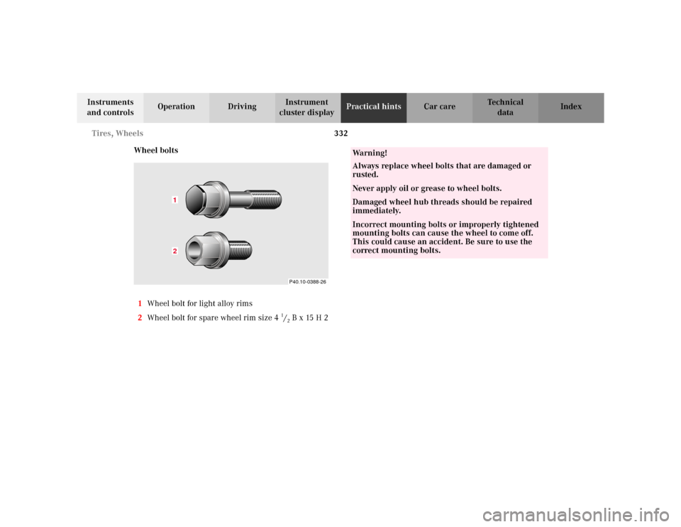
Wheel bolts
1Wheel bolt for light alloy rims
2Wheel bolt for spare wheel rim size 4
1/2 Bx15H2P40.10-0388-26
12
Wa r n i n g !
Always replace wheel bolts that are damaged or
rusted.Never apply oil or grease to wheel bolts.Damaged wheel hub threads should be repaired
immediately.Incorrect mounting bolts or improperly tightened
mounting bolts can cause the wheel to come off.
This could cause an accident. Be sure to use the
correct mounting bolts.