tires MERCEDES-BENZ C240 2001 W203 User Guide
[x] Cancel search | Manufacturer: MERCEDES-BENZ, Model Year: 2001, Model line: C240, Model: MERCEDES-BENZ C240 2001 W203Pages: 381, PDF Size: 19.92 MB
Page 272 of 381

263 Driving systems
Te ch n i c a l
data Instruments
and controlsOperationDrivingInstrument
cluster displayPractical hints Car care Index Notes:
Avoid spinning of one drive wheel. This may cause
serious damage to the drive train which is not covered
by the Mercedes-Benz Limited Warranty.
The ESP warning lamp, located in the speedometer dial,
starts to flash at any vehicle speed as soon as the tires
lose traction and the wheels begin to spin.
To return to the enhanced vehicle stability offered by
ESP: press lower half (2) of the switch (the ESP warning
lamp in the speedometer dial goes out).Important!
If the ESP warning lamp flashes:
•During take-off, apply as little throttle as possible.
•While driving, ease up on the accelerator.
Page 315 of 381
306 Tires, Wheels
Te ch n i c a l
data Instruments
and controlsOperation DrivingInstrument
cluster displayPractical hintsCar care Index
Wheels
Replace rims or tires with the same designation,
manufacturer and type as shown on the original part.
See your authorized Mercedes-Benz Center for further
information.
See your authorized Mercedes-Benz Center for
information on tested and recommended rims and tires
for summer and winter operation. They can also offer
advice concerning tire service and purchase.
Tire replacement
Front and rear tires should be replaced in sets. Rims
and tires must be of the correct size and type. For
dimensions, see “Technical Data”.
We recommend that you break in new tires for
approximately 60 miles (100 km) at moderate speed.
Wa r n i n g !
The jack is designed exclusively for jacking up the
vehi c le a t the j ack take-up b ra ckets b ui lt i nto eit her
side of the vehicle. To help avoid personal injury,
use the jack only to lift the vehicle during a wheel
change. Never get beneath the vehicle while it is
supported by the jack. Keep hands and feet away
from the area under the lifted vehicle. Always
firmly set parking brake and block wheels before
raising vehicle with jack.Do n ot d is engage parki n g brake w hil e t he vehi c le i s
raised. Be certain that the jack is always vertical
when in use, especially on hills. Always try to use
the jack on level surface. Be sure that the jack arm
is fully seated in the jack take-up bracket. Always
lower the vehicle onto sufficient capacity
jackstands before working under the vehicle.
Page 316 of 381
307 Tires, Wheels
Te ch n i c a l
data Instruments
and controlsOperation DrivingInstrument
cluster displayPractical hintsCar care Index It is imperative that the wheel mounting bolts be
fastened to a tightening torque of 110 ft.lb. (150 Nm)
whenever wheels are mounted.
For rim and tire specifications, refer to “Technical Data”.Rotating wheels
The wheels can be rotated according to the degree of
tire wear while retaining the same direction of travel.
Rotating, however, should be carried out as
recommended by the tire manufacturer, before the
characteristic tire wear pattern (shoulder wear on front
wheels and tread center wear on rear wheels) becomes
visible, as otherwise the driving properties deteriorate.
Notes:
Thoroughly clean the inner side of the wheels any time
you rotate the wheels or wash the vehicle underside.
The use of retread tires is not recommended. Retread
tires may adversely affect the handling characteristics
and safety of the vehicle.
Dented or bent rims can cause tire pressure loss and
damage to the tire beads. For this reason, check rims for
damage at regular intervals. The rim flanges must be
checked for wear before a tire is mounted. Remove
burrs, if any.
Check and ensure proper tire inflation pressure after
rotating the wheels. For tire inflation pressure see
inside of fuel filler flap and also page 264.
Wa r n i n g !
Worn, old tires can cause accidents. If the tire tread
is badly worn, or if the tires have sustained
damage, replace them.When replacing rims, use only genuine
Mercedes-Benz wheel bolts specified for the
particular rim type. Failure to do so can result in
the bolts loosening and possibly an accident.
Page 317 of 381
308 Tires, Wheels
Te ch n i c a l
data Instruments
and controlsOperation DrivingInstrument
cluster displayPractical hintsCar care Index
Spare wheel
Important!
The spare wheel rim is mounted with a full size tire of
the same type as on the vehicle, and is fully functional.
However, that spare wheel rim is weight optimized and
has a limited service life of 12 000 miles (20 000 km)
use before a standard wheel rim must replace it.
In the case of a flat tire, you may temporarily use the
spare wheel.
Do not operate vehicle with more than one spare wheel
mounted.Spare wheel
The spare wheel rim size is 7 J x 16 H2
(C 240 Canada only - steel rims 6
1/2 J x 16 H2).
In the case of a flat tire or breakdown, you may
temporarily use the spare wheel, while observing the
following restrictions:
•Do not exceed vehicle speed of 50 mph (80 km / h).
•Drive to the nearest repair facility to have the flat
tire repaired or replaced as appropriate.
•Do not operate vehicle with more than one spare
wheel mounted.
For additional information, refer to page 352.
Wa r n i n g !
The spare wheel rim is for temporary use only. Use
for over a total of 12 000 miles (20 000 km)
(aggregate of all uses) may cause wheel rim failure
leading to an accident and possible injuries.
Page 318 of 381
309 Tires, Wheels
Te ch n i c a l
data Instruments
and controlsOperation DrivingInstrument
cluster displayPractical hintsCar care Index Changing wheels
Wa r n i n g !
The spare wheel rim is for temporary use only. Use
for over a total of 12 000 miles (20 000 km) may
cause wheel rim failure leading to an accident and
possible injuries. The dimensions of the spare wheel are different
from those of road wheels. As a result, the vehicle
handling characteristics change when driving with
a mounted spare wheel.The spare wheel should only be used temporarily,
and replaced with a regular road wheel as quickly
as possible.
Wa r n i n g !
The jack is designed exclusively for jacking up the
vehic l e at t he j a ck ta ke-up brackets bui l t in to ei ther
side of the vehicle. To help avoid personal injury,
use the jack only to lift the vehicle during a wheel
change. Never get beneath the vehicle while it is
supported by the jack. Keep hands and feet away
from the area under the lifted vehicle. Always
firmly set parking brake and block wheels before
raising vehicle with jack.Do not d i sen ga ge park in g b ra ke whi l e the vehic l e is
raised. Be certain that the jack is always vertical
when in use, especially on hills. Always try to use
the jack on level surface. Be sure that the jack arm
is fully seated in the jack take-up bracket. Always
lower the vehicle onto sufficient capacity
jackstands before working under the vehicle.
Page 319 of 381
310 Tires, Wheels
Te ch n i c a l
data Instruments
and controlsOperation DrivingInstrument
cluster displayPractical hintsCar care Index
Move vehicle to a level area which is a safe distance
from the roadway.
1. Set parking brake and turn on hazard warning
flasher.
2. Move selector lever to position “P” and turn off
engine (manual transmission to 1st or reverse gear).
3. Prevent vehicle from rolling away by blocking
wheels with wheel chocks (not supplied with
vehicle) or sizable wood block or stone. When
changing a wheel on a hill, place chocks on the
downhill side blocking both wheels of the other
axle. On an level road, place one chock in front of
and one behind the wheel that is diagonally
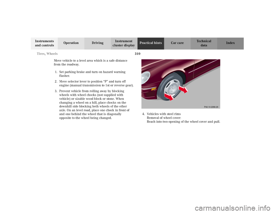
opposite to the wheel being changed.4. Vehicles with steel rims
Removal of wheel cover:
Reach into two opening of the wheel cover and pull.
P40.10-2356-26
Page 320 of 381
311 Tires, Wheels
Te ch n i c a l
data Instruments
and controlsOperation DrivingInstrument
cluster displayPractical hintsCar care Index 5. Remove the two-piece wheel wrench from the
vehicle tool kit and assemble (see page 305).
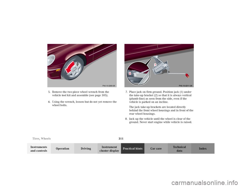
6. Using the wrench, loosen but do not yet remove the
wheel bolts.7. Place jack on firm ground. Position jack (1) under
the take-up bracket (2) so that it is always vertical
(plumb-line) as seen from the side, even if the
vehicle is parked on an incline.
The jack take-up brackets are located directly
behind the front wheel housings and in front of the
rear wheel housings.
8. Jack up the vehicle until the wheel is clear of the
ground. Never start engine while vehicle is raised.
P40.10-2283-26
Page 321 of 381

312 Tires, Wheels
Te ch n i c a l
data Instruments
and controlsOperation DrivingInstrument
cluster displayPractical hintsCar care Index
9. Unscrew upper-most wheel bolt and install
alignment bolt (1) supplied in the tool kit. Remove
the remaining bolts. Keep bolt threads protected
from dirt and sand.
10. Remove wheel. Grip wheel from the sides. Keep
hands from beneath the wheels.1Wheel bolt for light alloy rims
2Wheel bolt for steel rims (Canada model C 240)
P40.10-2284-26
Page 322 of 381
313 Tires, Wheels
Te ch n i c a l
data Instruments
and controlsOperation DrivingInstrument
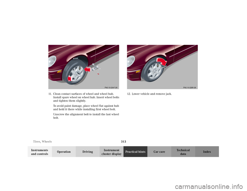
cluster displayPractical hintsCar care Index 11. Clean contact surfaces of wheel and wheel hub.
Install spare wheel on wheel hub. Insert wheel bolts
and tighten them slightly.
To avoid paint damage, place wheel flat against hub
and hold it there while installing first wheel bolt.
Unscrew the alignment bolt to install the last wheel
bolt.12. Lower vehicle and remove jack.
P40.10-2347-26
P40.10-2285-26
Page 323 of 381
314 Tires, Wheels
Te ch n i c a l
data Instruments
and controlsOperation DrivingInstrument
cluster displayPractical hintsCar care Index
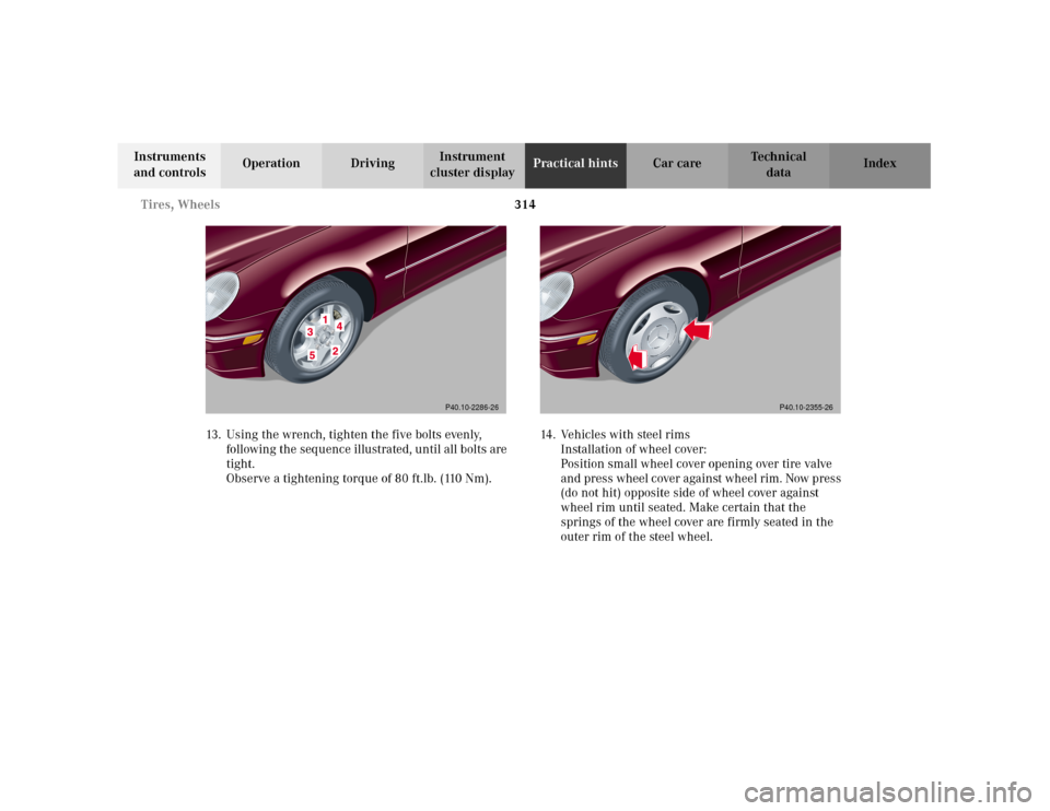
13. Using the wrench, tighten the five bolts evenly,
following the sequence illustrated, until all bolts are
tight.
Observe a tightening torque of 80 ft.lb. (110 Nm).14. Vehicles with steel rims
Installation of wheel cover:
Position small wheel cover opening over tire valve
and press wheel cover against wheel rim. Now press
(do not hit) opposite side of wheel cover against
wheel rim until seated. Make certain that the
springs of the wheel cover are firmly seated in the
outer rim of the steel wheel.
P40.10-2286-26
P40.10-2355-26