Clock MERCEDES-BENZ C300 4MATIC 2010 W204 User Guide
[x] Cancel search | Manufacturer: MERCEDES-BENZ, Model Year: 2010, Model line: C300 4MATIC, Model: MERCEDES-BENZ C300 4MATIC 2010 W204Pages: 364, PDF Size: 8.23 MB
Page 271 of 364
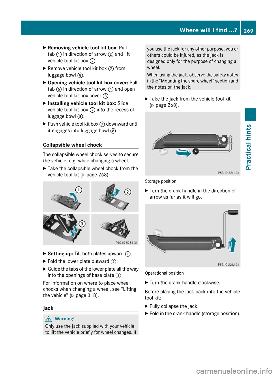
XRemoving vehicle tool kit box: Pull
tab : in direction of arrow ; and lift
vehicle tool kit box C.
XRemove vehicle tool kit box C from
luggage bowl D.
XOpening vehicle tool kit box cover: Pull
tab A in direction of arrow ? and open
vehicle tool kit box cover =.
XInstalling vehicle tool kit box: Slide
vehicle tool kit box C into the recess of
luggage bowl D.
XPush vehicle tool kit box C downward until
it engages into luggage bowl D.
Collapsible wheel chock
The collapsible wheel chock serves to secure
the vehicle, e.g. while changing a wheel.
XTake the collapsible wheel chock from the
vehicle tool kit (Y page 268).
XSetting up: Tilt both plates upward :.XFold the lower plate outward ;.XGuide the tabs of the lower plate all the way
into the openings of base plate =.
For information on where to place wheel
chocks when changing a wheel, see “Lifting
the vehicle” (Y page 318).
Jack
GWarning!
Only use the jack supplied with your vehicle
to lift the vehicle briefly for wheel changes. If
you use the jack for any other purpose, you or
others could be injured, as the jack is
designed only for the purpose of changing a
wheel.
When using the jack, observe the safety notes
in the “Mounting the spare wheel” section and
the notes on the jack.
XTake the jack from the vehicle tool kit
(Y page 268).
Storage position
XTurn the crank handle in the direction of
arrow as far as it will go.
Operational position
XTurn the crank handle clockwise.
Before placing the jack back into the vehicle
tool kit:
XFully collapse the jack.XFold in the crank handle (storage position).Where will I find ...?269Practical hints204_AKB; 5; 23, en-USd2ureepe,Version: 2.11.8.12009-07-16T17:54:06+02:00 - Seite 269Z
Page 272 of 364
Spare wheelGObserve Safety notes, see page 317.
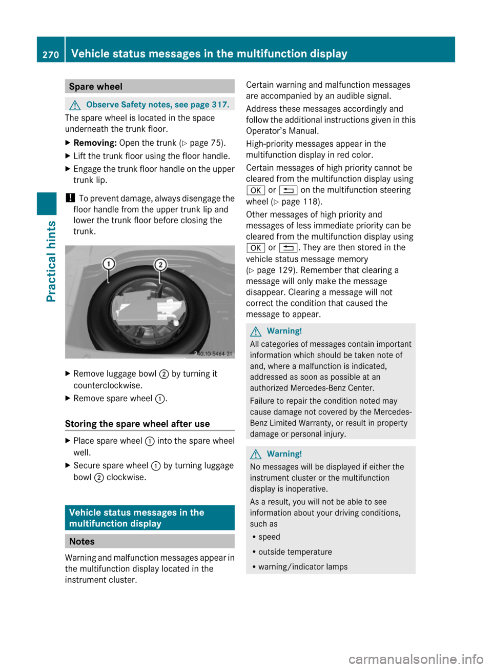
The spare wheel is located in the space
underneath the trunk floor.
XRemoving: Open the trunk (Y page 75).XLift the trunk floor using the floor handle.XEngage the trunk floor handle on the upper
trunk lip.
! To prevent damage, always disengage the
floor handle from the upper trunk lip and
lower the trunk floor before closing the
trunk.
XRemove luggage bowl ; by turning it
counterclockwise.
XRemove spare wheel :.
Storing the spare wheel after use
XPlace spare wheel : into the spare wheel
well.
XSecure spare wheel : by turning luggage
bowl ; clockwise.
Vehicle status messages in the
multifunction display
Notes
Warning and malfunction messages appear in
the multifunction display located in the
instrument cluster.
Certain warning and malfunction messages
are accompanied by an audible signal.
Address these messages accordingly and
follow the additional instructions given in this
Operator’s Manual.
High-priority messages appear in the
multifunction display in red color.
Certain messages of high priority cannot be
cleared from the multifunction display using
a or % on the multifunction steering
wheel (Y page 118).
Other messages of high priority and
messages of less immediate priority can be
cleared from the multifunction display using
a or %. They are then stored in the
vehicle status message memory
(Y page 129). Remember that clearing a
message will only make the message
disappear. Clearing a message will not
correct the condition that caused the
message to appear.
GWarning!
All categories of messages contain important
information which should be taken note of
and, where a malfunction is indicated,
addressed as soon as possible at an
authorized Mercedes-Benz Center.
Failure to repair the condition noted may
cause damage not covered by the Mercedes-
Benz Limited Warranty, or result in property
damage or personal injury.
GWarning!
No messages will be displayed if either the
instrument cluster or the multifunction
display is inoperative.
As a result, you will not be able to see
information about your driving conditions,
such as
Rspeed
Routside temperature
Rwarning/indicator lamps
270Vehicle status messages in the multifunction displayPractical hints
204_AKB; 5; 23, en-USd2ureepe,Version: 2.11.8.12009-07-16T17:54:06+02:00 - Seite 270
Page 311 of 364
GWarning!
If the 45 indicator lamp does not
illuminate or remains out with the weight of a
typical 12-month-old child in a standard child
restraint or less on the front passenger seat,
do not transport a child on the front
passenger seat until the system has been
repaired.
Unlocking/locking manually
Unlocking the vehicle
If you cannot unlock the vehicle with the
SmartKey or with KEYLESS-GO, unlock the
driver’s door and the trunk using the
mechanical key.
The anti-theft alarm system will trigger when
you
Runlock the driver’s door or the trunk with
the mechanical key
and
Ropen the driver’s door or the trunk
To cancel the alarm, insert the SmartKey into
the starter switch.
Removing the mechanical key
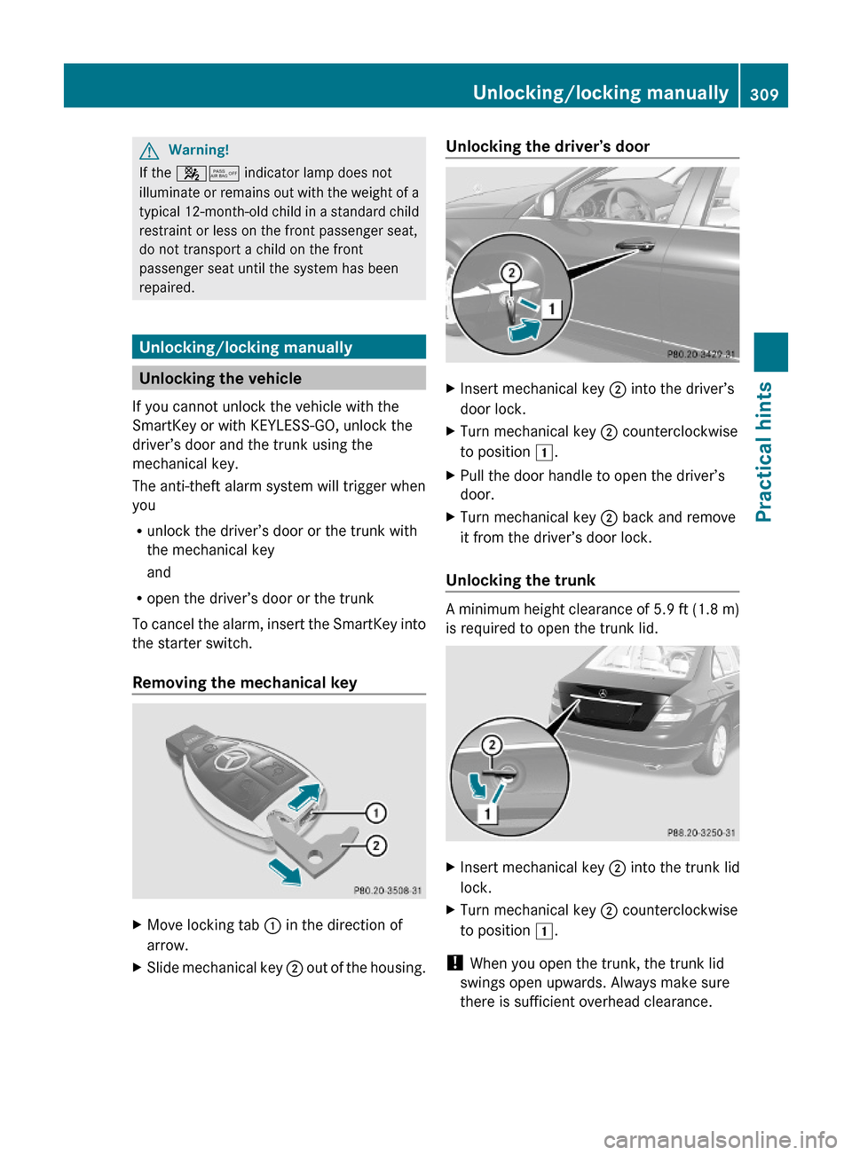
XMove locking tab : in the direction of
arrow.
XSlide mechanical key ; out of the housing.Unlocking the driver’s doorXInsert mechanical key ; into the driver’s
door lock.
XTurn mechanical key ; counterclockwise
to position 1.
XPull the door handle to open the driver’s
door.
XTurn mechanical key ; back and remove
it from the driver’s door lock.
Unlocking the trunk
A minimum height clearance of 5.9 ft (1.8 m)
is required to open the trunk lid.
XInsert mechanical key ; into the trunk lid
lock.
XTurn mechanical key ; counterclockwise
to position 1.
! When you open the trunk, the trunk lid
swings open upwards. Always make sure
there is sufficient overhead clearance.
Unlocking/locking manually309Practical hints204_AKB; 5; 23, en-USd2ureepe,Version: 2.11.8.12009-07-16T17:54:06+02:00 - Seite 309Z
Page 312 of 364
XTurn mechanical key ; back and remove
it from the trunk lid lock.
Locking the vehicle
If you cannot lock the vehicle with the
SmartKey or with KEYLESS-GO, lock it as
follows:
XOpen the driver’s door.XClose the front passenger door, the rear
doors, and the trunk.
XPress the central locking switch
(Y page 75).
The locking knobs of the front passenger
door and the rear doors move down.
XIf the vehicle battery is disconnected or
drained: Press down the locking knobs on
the front passenger door and the rear
doors.
XExit the vehicle.XClose the driver’s door.XRemove mechanical key ; from the
SmartKey (Y page 309).
XInsert mechanical key ; into the driver’s
door lock.
XTurn mechanical key ; clockwise to
position 1.
The vehicle is locked.
XTurn mechanical key ; back and remove
it from the driver’s door lock.
XCheck whether the doors and the trunk are
locked.
XIf necessary, lock the trunk with the
mechanical key (Y page 77).
iThis procedure does not arm the anti-
theft alarm system, nor does it lock the fuel
filler flap.
Fuel filler flap
GWarning!
Avoid contact with the vehicle walls as they
may contain sharp edges. Otherwise, you
could injure yourself while releasing the fuel
filler flap.
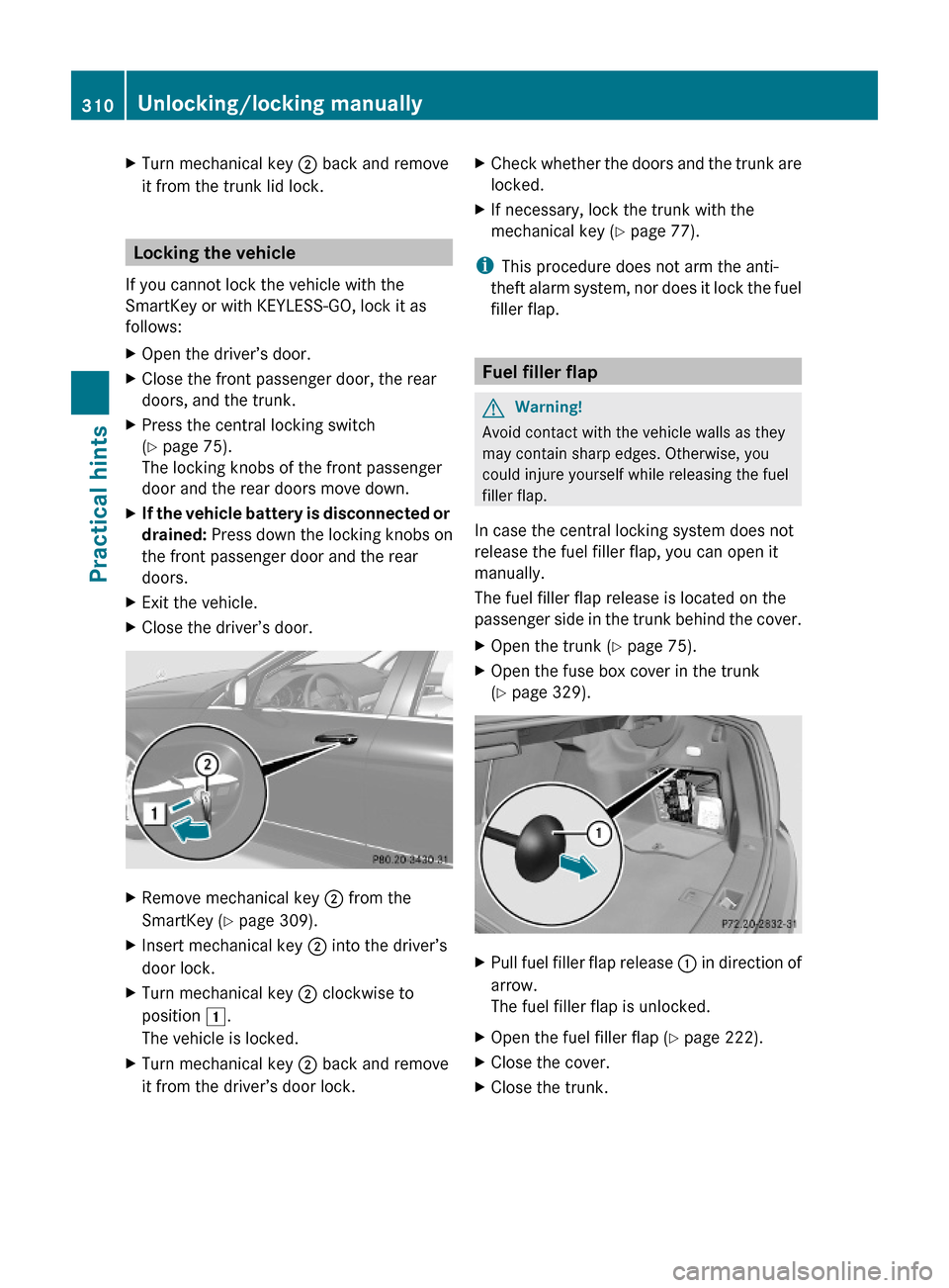
In case the central locking system does not
release the fuel filler flap, you can open it
manually.
The fuel filler flap release is located on the
passenger side in the trunk behind the cover.
XOpen the trunk (Y page 75).XOpen the fuse box cover in the trunk
(Y page 329).
XPull fuel filler flap release : in direction of
arrow.
The fuel filler flap is unlocked.
XOpen the fuel filler flap (Y page 222).XClose the cover.XClose the trunk.310Unlocking/locking manuallyPractical hints
204_AKB; 5; 23, en-USd2ureepe,Version: 2.11.8.12009-07-16T17:54:06+02:00 - Seite 310
Page 317 of 364
GObserve Safety notes, see page 313.
ROnly use 12-volt bulbs of the same type and
with the specified watt rating.
RSwitch the lights off before changing a bulb
to prevent short circuits.
RAlways use a clean lint-free cloth when
handling bulbs.
RYour hands should be dry and free of oil and
grease.
RIf the newly installed bulb does not come
on, contact an authorized Mercedes-Benz
Center.
iMercedes-Benz recommends using
Longlife (LL) bulbs.
Replacing bulbs for front lamps
XSwitch off the ignition.XTurn the exterior lamp switch to position
$.
XOpen the hood (Y page 224).GWarning!
Do not remove the cover for the Bi-Xenon
headlamp. Because of high voltage in Xenon
lamps, it is dangerous to replace the bulb or
repair the lamp and its components. It is
recommended to have such work done by a
qualified technician.
Low-beam bulb (halogen headlamps
only)
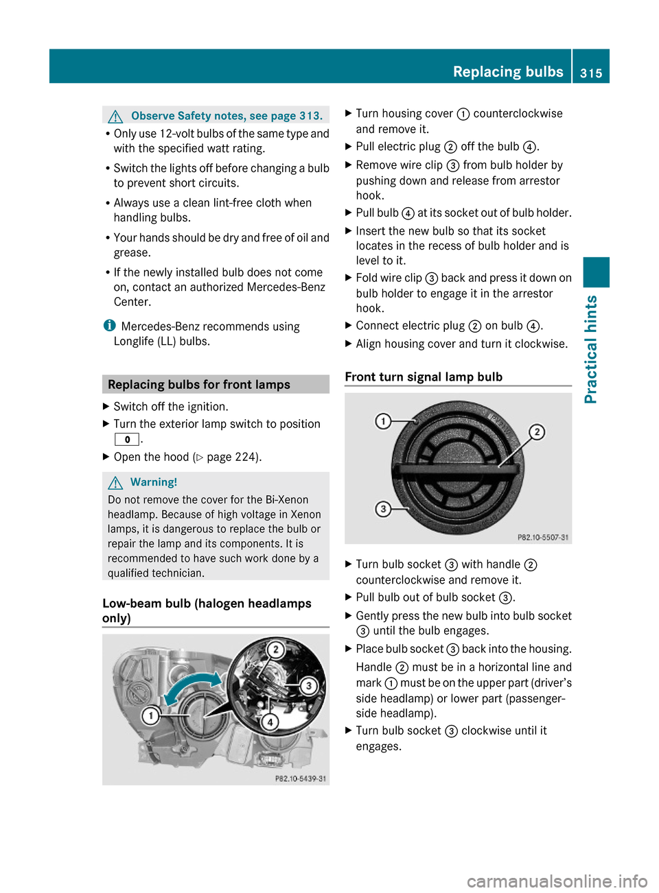
XTurn housing cover : counterclockwise
and remove it.
XPull electric plug ; off the bulb ?.XRemove wire clip = from bulb holder by
pushing down and release from arrestor
hook.
XPull bulb ? at its socket out of bulb holder.XInsert the new bulb so that its socket
locates in the recess of bulb holder and is
level to it.
XFold wire clip = back and press it down on
bulb holder to engage it in the arrestor
hook.
XConnect electric plug ; on bulb ?.XAlign housing cover and turn it clockwise.
Front turn signal lamp bulb
XTurn bulb socket = with handle ;
counterclockwise and remove it.
XPull bulb out of bulb socket =.XGently press the new bulb into bulb socket
= until the bulb engages.
XPlace bulb socket = back into the housing.
Handle ; must be in a horizontal line and
mark : must be on the upper part (driver’s
side headlamp) or lower part (passenger-
side headlamp).
XTurn bulb socket = clockwise until it
engages.
Replacing bulbs315Practical hints204_AKB; 5; 23, en-USd2ureepe,Version: 2.11.8.12009-07-16T17:54:06+02:00 - Seite 315Z
Page 318 of 364
Replacing bulbs for rear lamps
Before you start to replace a bulb for a rear
lamp, do the following:
XSwitch off the ignition.XTurn the exterior lamp switch to position
$.
XOpen the trunk.
Tail lamp unit
XDriver’s side: Lift up the bottom and pull out
the trim panel covering the driver side rear
light.
XPassenger side: Open the fuse box in the
trunk (Y page 329).
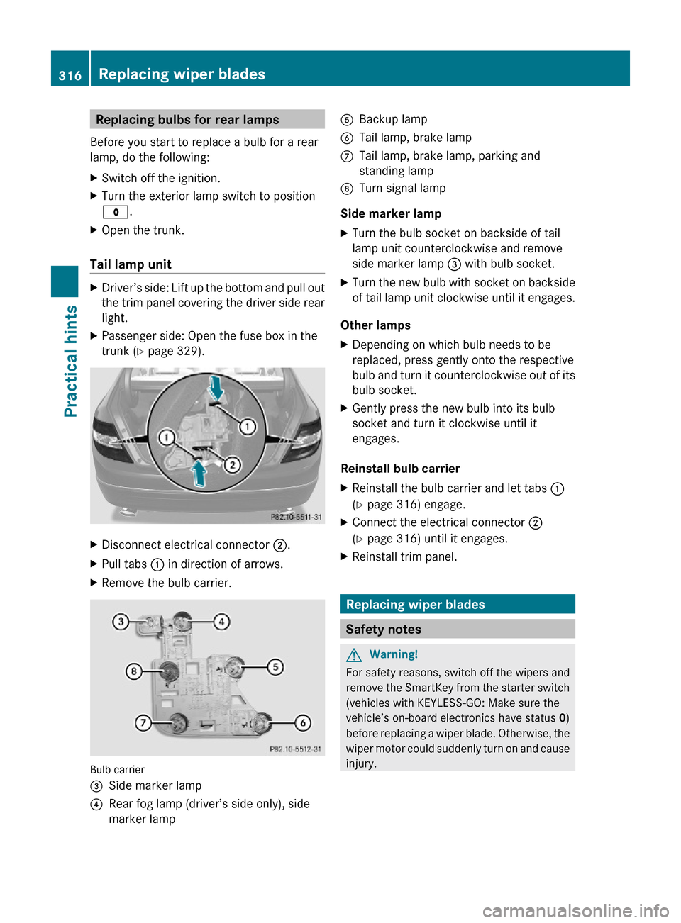
XDisconnect electrical connector ;.XPull tabs : in direction of arrows.XRemove the bulb carrier.
Bulb carrier
=Side marker lamp?Rear fog lamp (driver’s side only), side
marker lamp
ABackup lampBTail lamp, brake lampCTail lamp, brake lamp, parking and
standing lamp
DTurn signal lamp
Side marker lamp
XTurn the bulb socket on backside of tail
lamp unit counterclockwise and remove
side marker lamp = with bulb socket.
XTurn the new bulb with socket on backside
of tail lamp unit clockwise until it engages.
Other lamps
XDepending on which bulb needs to be
replaced, press gently onto the respective
bulb and turn it counterclockwise out of its
bulb socket.
XGently press the new bulb into its bulb
socket and turn it clockwise until it
engages.
Reinstall bulb carrier
XReinstall the bulb carrier and let tabs :
(Y page 316) engage.
XConnect the electrical connector ;
(Y page 316) until it engages.
XReinstall trim panel.
Replacing wiper blades
Safety notes
GWarning!
For safety reasons, switch off the wipers and
remove the SmartKey from the starter switch
(vehicles with KEYLESS-GO: Make sure the
vehicle’s on-board electronics have status 0)
before replacing a wiper blade. Otherwise, the
wiper motor could suddenly turn on and cause
injury.
316Replacing wiper bladesPractical hints
204_AKB; 5; 23, en-USd2ureepe,Version: 2.11.8.12009-07-16T17:54:06+02:00 - Seite 316
Page 322 of 364
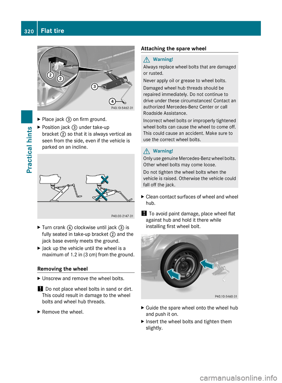
XPlace jack = on firm ground.XPosition jack = under take-up
bracket ; so that it is always vertical as
seen from the side, even if the vehicle is
parked on an incline.
XTurn crank ? clockwise until jack = is
fully seated in take-up bracket ; and the
jack base evenly meets the ground.
XJack up the vehicle until the wheel is a
maximum of 1.2 in (3 cm) from the ground.
Removing the wheel
XUnscrew and remove the wheel bolts.
! Do not place wheel bolts in sand or dirt.
This could result in damage to the wheel
bolts and wheel hub threads.
XRemove the wheel.Attaching the spare wheelGWarning!
Always replace wheel bolts that are damaged
or rusted.
Never apply oil or grease to wheel bolts.
Damaged wheel hub threads should be
repaired immediately. Do not continue to
drive under these circumstances! Contact an
authorized Mercedes-Benz Center or call
Roadside Assistance.
Incorrect wheel bolts or improperly tightened
wheel bolts can cause the wheel to come off.
This could cause an accident. Make sure to
use the correct wheel bolts.
GWarning!
Only use genuine Mercedes-Benz wheel bolts.
Other wheel bolts may come loose.
Do not tighten the wheel bolts when the
vehicle is raised. Otherwise the vehicle could
fall off the jack.
XClean contact surfaces of wheel and wheel
hub.
! To avoid paint damage, place wheel flat
against hub and hold it there while
installing first wheel bolt.
XGuide the spare wheel onto the wheel hub
and push it on.
XInsert the wheel bolts and tighten them
slightly.
320Flat tirePractical hints
204_AKB; 5; 23, en-USd2ureepe,Version: 2.11.8.12009-07-16T17:54:06+02:00 - Seite 320
Page 323 of 364
Lowering the vehicleXLower the vehicle by turning the crank
counterclockwise until the vehicle is
resting fully on its own weight.
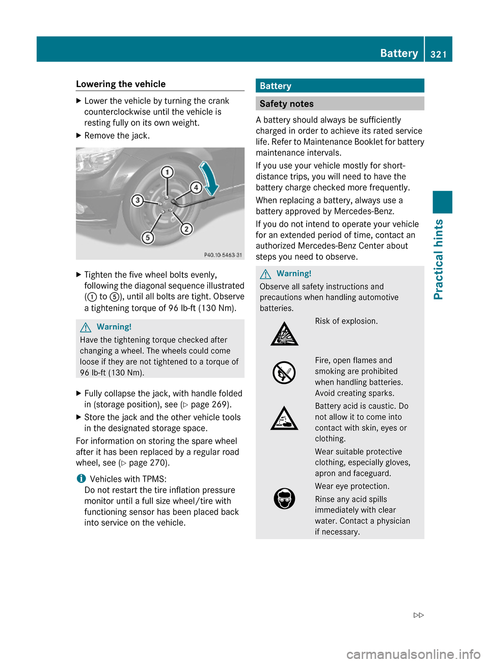
XRemove the jack.XTighten the five wheel bolts evenly,
following the diagonal sequence illustrated
(: to A), until all bolts are tight. Observe
a tightening torque of 96 lb-ft (130 Nm).
GWarning!
Have the tightening torque checked after
changing a wheel. The wheels could come
loose if they are not tightened to a torque of
96 lb-ft (130 Nm).
XFully collapse the jack, with handle folded
in (storage position), see (Y page 269).
XStore the jack and the other vehicle tools
in the designated storage space.
For information on storing the spare wheel
after it has been replaced by a regular road
wheel, see (Y page 270).
iVehicles with TPMS:
Do not restart the tire inflation pressure
monitor until a full size wheel/tire with
functioning sensor has been placed back
into service on the vehicle.
Battery
Safety notes
A battery should always be sufficiently
charged in order to achieve its rated service
life. Refer to Maintenance Booklet for battery
maintenance intervals.
If you use your vehicle mostly for short-
distance trips, you will need to have the
battery charge checked more frequently.
When replacing a battery, always use a
battery approved by Mercedes-Benz.
If you do not intend to operate your vehicle
for an extended period of time, contact an
authorized Mercedes-Benz Center about
steps you need to observe.
GWarning!
Observe all safety instructions and
precautions when handling automotive
batteries.
Risk of explosion.Fire, open flames and
smoking are prohibited
when handling batteries.
Avoid creating sparks.
Battery acid is caustic. Do
not allow it to come into
contact with skin, eyes or
clothing.
Wear suitable protective
clothing, especially gloves,
apron and faceguard.
Wear eye protection.
Rinse any acid spills
immediately with clear
water. Contact a physician
if necessary.
Battery321Practical hints204_AKB; 5; 23, en-USd2ureepe,Version: 2.11.8.12009-07-16T17:54:06+02:00 - Seite 321Z
Page 324 of 364
Keep children away.Follow the instructions in
this Operator’s Manual.
A battery contains materials that can harm
the environment if disposed of improperly. A
large 12 V storage battery contains lead.
Recycling of the battery is the preferred
method of disposal. Many states (USA only)
or provinces (Canada only) require sellers of
batteries to accept the old battery for
recycling.
GWarning!
Failure to follow these instructions can result
in severe injury or death.
Never lean over batteries while connecting.
You might get injured.
Battery fluid contains sulfuric acid. Do not
allow this fluid to come in contact with eyes,
skin or clothing. In case it does, immediately
flush affected area with water and seek
medical help if necessary.
A battery will also produce hydrogen gas,
which is flammable and explosive. Keep
flames or sparks away from battery, avoid
improper connection of jumper cables,
smoking etc.
GWarning!
Do not place metal objects on the battery as
this could result in a short circuit.
Use leak-proof batteries only to avoid the risk
of acid burns in the event of an accident.
Take care that you do not become statically
charged, e.g. by wearing synthetic clothing or
rubbing against textiles. For this reason, you
also should not pull or push the battery over
carpets or other synthetic materials.
Never touch the battery first. First touch the
outside body of the vehicle in order to release
any possible electrostatic charges.
Do not rub the battery with rags or cloths. The
battery could explode if touched due to
electrostatic charge or due to spark
formation.
! As any other battery, the battery may
discharge if you do not operate the vehicle
for an extended period of time. Have the
battery disconnected at a qualified
workshop or an authorized Mercedes-Benz
Center in such a case. You may also
connect an accessory battery charge unit
expressly approved by Mercedes-Benz for
your vehicle model to maintain the battery
charge. Contact an authorized Mercedes-
Benz Center for further information.
The battery, the battery ventilation hose
and the lateral plug must always be
securely installed when the vehicle is in
operation.
! Never loosen or detach battery terminal
clamps while the engine is running or the
SmartKey is in the starter switch or
KEYLESS-GO button is in position 1.
Otherwise the alternator and other
electronic components could be severely
damaged.
Have the battery checked regularly at an
authorized Mercedes-Benz Center.
Refer to Maintenance Booklet for
maintenance intervals or contact an
authorized Mercedes-Benz Center for
further information.
i After battery power was interrupted, do
the following:
R Reset the automatic exterior mirror fold
in function ( Y page 88).
R Set the clock (Y page 132). Vehicles with
COMAND: see separate COMAND
operating instructions.322BatteryPractical hints
204_AKB; 5; 23, en-USd2ureepe,Version: 2.11.8.12009-07-16T17:54:06+02:00 - Seite 322
Page 328 of 364
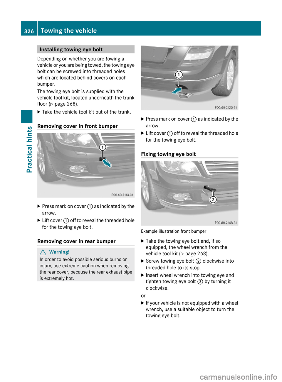
Installing towing eye bolt
Depending on whether you are towing a
vehicle or you are being towed, the towing eye
bolt can be screwed into threaded holes
which are located behind covers on each
bumper.
The towing eye bolt is supplied with the
vehicle tool kit, located underneath the trunk
floor (Y page 268).
XTake the vehicle tool kit out of the trunk.
Removing cover in front bumper
XPress mark on cover : as indicated by the
arrow.
XLift cover : off to reveal the threaded hole
for the towing eye bolt.
Removing cover in rear bumper
GWarning!
In order to avoid possible serious burns or
injury, use extreme caution when removing
the rear cover, because the rear exhaust pipe
is extremely hot.
XPress mark on cover : as indicated by the
arrow.
XLift cover : off to reveal the threaded hole
for the towing eye bolt.
Fixing towing eye bolt
Example illustration front bumper
XTake the towing eye bolt and, if so
equipped, the wheel wrench from the
vehicle tool kit (Y page 268).
XScrew towing eye bolt ; clockwise into
threaded hole to its stop.
XInsert wheel wrench into towing eye and
tighten towing eye bolt ; by turning it
clockwise.
or
XIf your vehicle is not equipped with a wheel
wrench, use a suitable object to turn the
towing eye bolt.
326Towing the vehiclePractical hints
204_AKB; 5; 23, en-USd2ureepe,Version: 2.11.8.12009-07-16T17:54:06+02:00 - Seite 326