brake MERCEDES-BENZ C320 2001 W203 Service Manual
[x] Cancel search | Manufacturer: MERCEDES-BENZ, Model Year: 2001, Model line: C320, Model: MERCEDES-BENZ C320 2001 W203Pages: 381, PDF Size: 19.92 MB
Page 288 of 381
279 Malfunction and warning messages
Te ch n i c a l
data Instruments
and controlsOperation DrivingInstrument
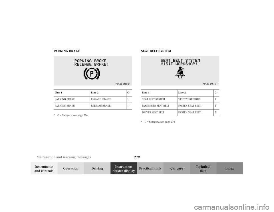
cluster displayPractical hints Car care Index PA R K I N G B R A K E
* C = Category, see page 274
SEAT BELT SYSTEM* C = Category, see page 274 Line 1 Line 2 C*
PARKING BRAKE ENGAGE BRAKE! 1
PARKING BRAKE RELEASE BRAKE! 1Line 1 Line 2 C*
SEAT BELT SYSTEM VISIT WORKSHOP! 1
PASSENGER SEAT BELT FASTEN SEAT BELT! 2
DRIVER SEAT BELT FASTEN SEAT BELT! 2
Page 293 of 381
284 Malfunction and warning messages
Te ch n i c a l
data Instruments
and controlsOperation DrivingInstrument
cluster displayPractical hints Car care Index
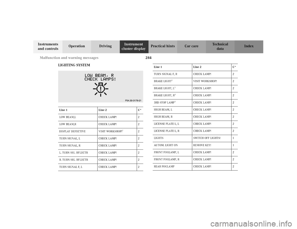
LIGHTING SYSTEM
Line 1 Line 2 C*
LOW BEAM,L CHECK LAMP! 2
LOW BEAM,R CHECK LAMP! 2
DISPLAY DEFECTIVE VISIT WORKSHOP!
1
2
TURN SIGNAL, L CHECK LAMP! 2
TURN SIGNAL, R CHECK LAMP! 2
L. TURN SIG. RFLECTR CHECK LAMP! 2
R. TURN SIG. RFLECTR CHECK LAMP! 2
TURN SIGNAL F, L CHECK LAMP! 2
TURN SIGNAL F, R CHECK LAMP! 2
BRAKE LIGHT
2
VISIT WORKSHOP! 2
BRAKE LIGHT, L
3
CHECK LAMP! 2
BRAKE LIGHT, R
3
CHECK LAMP! 2
3RD STOP LAMP
3
CHECK LAMP! 2
HIGH BEAM, L CHECK LAMP! 2
HIGH BEAM, R CHECK LAMP! 2
LICENSE PLATE L, L CHECK LAMP! 2
LICENSE PLATE L, R CHECK LAMP! 2
LIGHTS SWITCH OFF LIGHTS! 1
AUTOM. LIGHT ON REMOVE KEY! 1
FRONT FOGLAMP, L CHECK LAMP! 2
FRONT FOGLAMP, R CHECK LAMP! 2
REAR FOGLAMP CHECK LAMP! 2 Line 1 Line 2 C*
Page 294 of 381

285 Malfunction and warning messages
Te ch n i c a l
data Instruments
and controlsOperation DrivingInstrument
cluster displayPractical hints Car care IndexIn t he case of bulb failures in certain lamps, ot her lamps
will substitute. See page 326 for instructions on
replacing bulbs.
* C = Category, see page 274
1 The display or the system is malfunctioning.
2 The brake lamps are switching on after a delay or are permanently
on – visit workshop immediately.
3 The brake lamp comprises several light emitting diodes. The
warning message will only appear if all light emitting diodes have
stopped working.
4 Other bulbs will be brought into use as replacements when certain
lamps blow. REAR FOGLAMP SWITCH OFF
SUBSTITUTE LAMP ON!
4
2
REVERSE LIGHT, L CHECK LAMP! 2
REVERSE LIGHT, R CHECK LAMP! 2
TAIL LIGHT, L CHECK LAMP!
SUBSTITUTE LAMP ON!
4
2
TAIL LIGHT, R CHECK LAMP!
SUBSTITUTE LAMP ON!
4
2
SIDELIGHT, L CHECK LAMP!
SUBSTITUTE LAMP ON!
4
2
SIDELIGHT, R CHECK LAMP!
SUBSTITUTE LAMP ON!
4
2 Line 1 Line 2 C*
Page 304 of 381
295 Fuses
Te ch n i c a l
data Instruments
and controlsOperation DrivingInstrument
cluster displayPractical hintsCar care Index Fuses
Most of your vehicle’s electrical components are fused
with safety fuses. With the exception of the brake lights,
all individual lighting system components are
electronically fused. Before replacing a blown safety
fuse, determine the cause of the short circuit. Always
observe amperage and color of fuse.
The circuit for components is protected by a cycled
circuit breaker interrupted if too much current is being
drawn. The circuit closes automatically after a short
time; the circuit is broken again if the malfunction
reoccurs.
A lways us e a new fus e for re placeme nt. Never atte mp t to
repair or bridge a blown fuse.
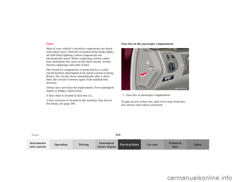
A fuse chart is located in fuse box (1).
A fuse extractor is located in the auxiliary fuse box in
the trunk, see page 296.Fuse box in the passenger compartment
1Fuse box in passenger compartment
To gain access to fuse box, pull cover away from fuse
box (arrow) and remove rearward.
Page 315 of 381
306 Tires, Wheels
Te ch n i c a l
data Instruments
and controlsOperation DrivingInstrument
cluster displayPractical hintsCar care Index
Wheels
Replace rims or tires with the same designation,
manufacturer and type as shown on the original part.
See your authorized Mercedes-Benz Center for further
information.
See your authorized Mercedes-Benz Center for
information on tested and recommended rims and tires
for summer and winter operation. They can also offer
advice concerning tire service and purchase.
Tire replacement
Front and rear tires should be replaced in sets. Rims
and tires must be of the correct size and type. For
dimensions, see “Technical Data”.
We recommend that you break in new tires for
approximately 60 miles (100 km) at moderate speed.
Wa r n i n g !
The jack is designed exclusively for jacking up the
vehi c le a t the j ack take-up b ra ckets b ui lt i nto eit her
side of the vehicle. To help avoid personal injury,
use the jack only to lift the vehicle during a wheel
change. Never get beneath the vehicle while it is
supported by the jack. Keep hands and feet away
from the area under the lifted vehicle. Always
firmly set parking brake and block wheels before
raising vehicle with jack.Do n ot d is engage parki n g brake w hil e t he vehi c le i s
raised. Be certain that the jack is always vertical
when in use, especially on hills. Always try to use
the jack on level surface. Be sure that the jack arm
is fully seated in the jack take-up bracket. Always
lower the vehicle onto sufficient capacity
jackstands before working under the vehicle.
Page 318 of 381
309 Tires, Wheels
Te ch n i c a l
data Instruments
and controlsOperation DrivingInstrument
cluster displayPractical hintsCar care Index Changing wheels
Wa r n i n g !
The spare wheel rim is for temporary use only. Use
for over a total of 12 000 miles (20 000 km) may
cause wheel rim failure leading to an accident and
possible injuries. The dimensions of the spare wheel are different
from those of road wheels. As a result, the vehicle
handling characteristics change when driving with
a mounted spare wheel.The spare wheel should only be used temporarily,
and replaced with a regular road wheel as quickly
as possible.
Wa r n i n g !
The jack is designed exclusively for jacking up the
vehic l e at t he j a ck ta ke-up brackets bui l t in to ei ther
side of the vehicle. To help avoid personal injury,
use the jack only to lift the vehicle during a wheel
change. Never get beneath the vehicle while it is
supported by the jack. Keep hands and feet away
from the area under the lifted vehicle. Always
firmly set parking brake and block wheels before
raising vehicle with jack.Do not d i sen ga ge park in g b ra ke whi l e the vehic l e is
raised. Be certain that the jack is always vertical
when in use, especially on hills. Always try to use
the jack on level surface. Be sure that the jack arm
is fully seated in the jack take-up bracket. Always
lower the vehicle onto sufficient capacity
jackstands before working under the vehicle.
Page 319 of 381
310 Tires, Wheels
Te ch n i c a l
data Instruments
and controlsOperation DrivingInstrument
cluster displayPractical hintsCar care Index
Move vehicle to a level area which is a safe distance
from the roadway.
1. Set parking brake and turn on hazard warning
flasher.
2. Move selector lever to position “P” and turn off
engine (manual transmission to 1st or reverse gear).
3. Prevent vehicle from rolling away by blocking
wheels with wheel chocks (not supplied with
vehicle) or sizable wood block or stone. When
changing a wheel on a hill, place chocks on the
downhill side blocking both wheels of the other
axle. On an level road, place one chock in front of
and one behind the wheel that is diagonally
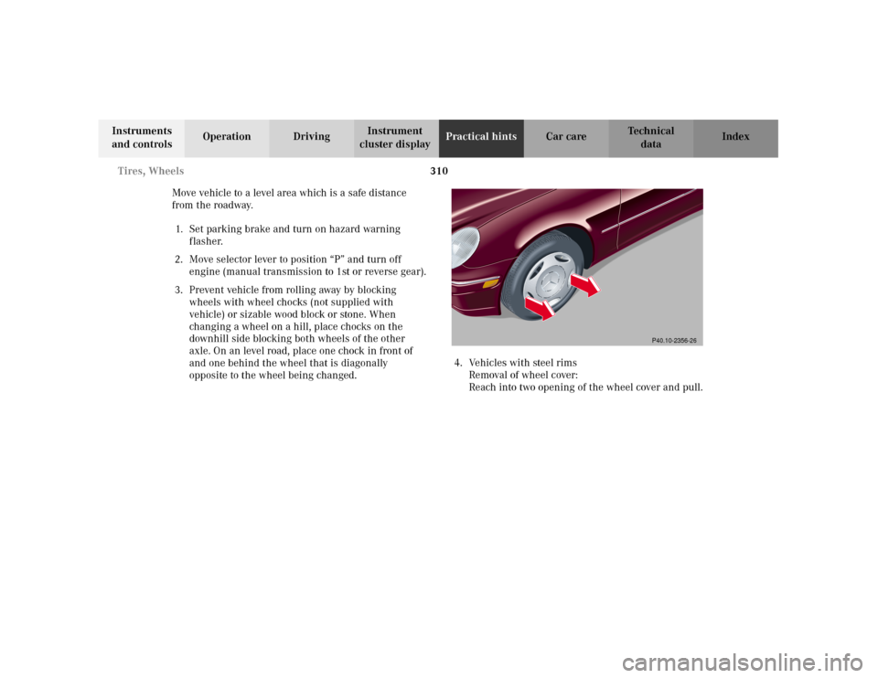
opposite to the wheel being changed.4. Vehicles with steel rims
Removal of wheel cover:
Reach into two opening of the wheel cover and pull.
P40.10-2356-26
Page 329 of 381

320 Jump starting
Te ch n i c a l
data Instruments
and controlsOperation DrivingInstrument
cluster displayPractical hintsCar care Index
Proceed as follows:
1. Position the vehicle with the charged battery so that
the jumper cables will reach, but never let the
vehicles touch. Make sure the jumper cables do not
have loose or missing insulation.
2. On both vehicles:
•Turn off engine and all lights and accessories,
except hazard warning flashers or work lights.
•Apply parking brake and shift selector lever to
position “P” (manual transmission to Neutral).
Important!
3. Clamp one end of the first jumper cable to the
positive (+) under hood terminal of the discharged
battery and the other end to the positive (+) terminal
of the charged battery. Make sure the cable clamps
do not touch any other metal parts.
4. Clamp one end of the second jumper cable to the
grounded negative (–) terminal of the charged
battery and the final connection to the negative (–)
under hood terminal of the disabled vehicle.Important!
5. Start engine of the vehicle with the charged battery
and run at high idle. Make sure the cables are not
on or near pulleys, fans, or other parts that move
when the engine is started. Allow the discharged
battery to charge for a few minutes. Start engine of
the disabled vehicle in the usual manner.
6. After the engine has started, remove jumper cables
by exactly reversing the above installation
sequence, starting with the last connection made
first. When removing each clamp, make sure that it
does not touch any other metal while the other end
is still attached.
Page 333 of 381
324 Towing the vehicle
Te ch n i c a l
data Instruments
and controlsOperation DrivingInstrument
cluster displayPractical hintsCar care Index
Use wheel lift, dolly, or flat bed equipment, with
electronic key in starter switch turned to position 0.
Note:
To signal turns while being towed with hazard warning
flasher in use, turn electronic key in starter switch to
position 2 and activate combination switch for left or
right turn signal in usual manner – only the selected
turn signal will operate.Upon canceling the turn signal, the hazard warning
flasher will operate again.
Caution!
If the vehicle is towed with the front axle raised, the
engine must be shut off (electronic key in starter switch
position 0 or 1). Otherwise, the ESP will immediately be
engaged and will apply the rear wheel brakes.
Switch off the tow-away alarm (see page 39) as well as
the ESP (see page 260).
Wa r n i n g !
With the engine not running, there is no power
assistance for the braking and steering systems. In
this case, it is important to keep in mind that a
considerably higher degree of effort is necessary to
brake and steer the vehicle.
Page 339 of 381
330 Exterior lamps
Te ch n i c a l
data Instruments
and controlsOperation DrivingInstrument
cluster displayPractical hintsCar care Index
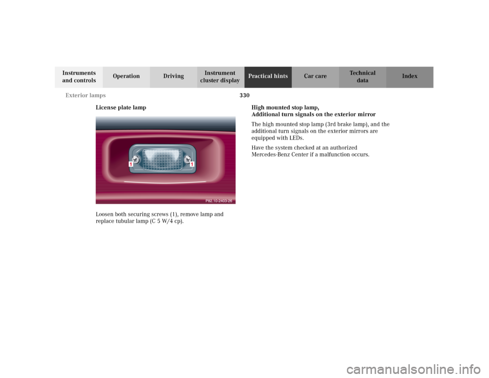
License plate lamp
Loosen both securing screws (1), remove lamp and
replace tubular lamp (C 5 W/4 cp).High mounted stop lamp,
Additional turn signals on the exterior mirror
The high mounted stop lamp (3rd brake lamp), and the
additional turn signals on the exterior mirrors are
equipped with LEDs.
Have the system checked at an authorized
Mercedes-Benz Center if a malfunction occurs.