brake MERCEDES-BENZ C320 WAGON 2002 S203 Owner's Manual
[x] Cancel search | Manufacturer: MERCEDES-BENZ, Model Year: 2002, Model line: C320 WAGON, Model: MERCEDES-BENZ C320 WAGON 2002 S203Pages: 390
Page 7 of 390

4 Contents
DrivingControl and operation of
radio transmitters .....................226
The first 1 000 miles
(1 500 km) .................................227
Maintenance ...................................227
Tele Aid ...........................................228
Catalytic converter ........................238
Emission control ............................239
Starter switch .................................240
Starting and turning off
the engine ..................................242
Automatic transmission ...............243
Parking brake .................................252
Driving instructions ......................253
Drive sensibly – Save Fuel ........253
Drinking and driving .................253
Pedals ...........................................253
Power assistance ........................254
Brakes ..........................................254
Driving off ...................................255
Parking ........................................256
Tires .............................................257Snow chains ............................... 259
Winter driving
instructions ................................ 260
Deep water .................................. 262
Passenger compartment ........... 263
Traveling abroad ........................ 263
Cruise control ................................ 264
Brake assist system (BAS) ............ 267
Antilock brake system
(ABS) .......................................... 268
Electronic stability program
(ESP) ........................................... 270
What you should know
at the gas station .......................274
Check regularly and
before a long trip .......................276
Instrument cluster displayMalfunction and indicator lamps in
the instrument cluster ............. 278
On-board diagnostic system ........ 278
Check engine malfunction
indicator lamp ............................ 278
Brake warning lamp .................. 280Supplemental restraint system
(SRS) indicator lamp .................. 281
Fuel reserve warning .................282
ABS malfunction
indicator lamp .............................283
Electronic stability program
(ESP) — warning lamp ...............284
Seat belt nonusage
warning lamp ............................284
Malfunction and indicator
lamp in the center console ......284
AIRBAG OFF indicator lamp .....284
Malfunction and warning
messages in the
multifunction display ...............285
DISPLAY DEFECTIVE ................287
BATTERY / ALTERNATOR ........288
ANTILOCK BRAKE SYSTEM ....289
BRAKE ASSIST ...........................289
BRAKE PAD WEAR ....................290
BRAKE FLUID .............................290
PARKING BRAKE ....................... 291
SEAT BELT SYSTEM ................... 291
S203.book Seite 4 Freitag, 19. Oktober 2001 1:25 13
Page 9 of 390

6 Contents
Vehicle careCleaning and care of the vehicle .354
Power washer ..............................355
Tar stains .....................................355
Paintwork, painted body
components .................................355
Engine cleaning ..........................356
Vehicle washing .........................356
Ornamental moldings ................357
Headlamps, taillamps,
turn signal lenses ......................357
Window cleaning ........................357
Wiper blade .................................357
Light alloy wheels ......................358
Instrument cluster .....................358
Steering wheel and
gear selector lever ......................358
Cup holder ...................................358
Seat belts .....................................359
Headliner and
shelf below rear window ...........359Leather upholstery .................... 359
Hard plastic trim items ............. 359
Plastic and rubber parts ........... 359
Technical dataSpare parts service ....................... 362
Warranty coverage ........................ 362
Identification labels ...................... 363
Layout of poly-V-belt drive ........... 364
Technical data ................................ 365
Fuels, coolants, lubricants etc. -
capacities ................................... 368
Engine oils ...................................... 370
Engine oil additives ...................... 370
Air conditioner refrigerant .......... 370
Brake fluid ...................................... 370
Premium unleaded gasoline .........371
Fuel requirements .........................371
Gasoline additives ......................... 372
Coolants .......................................... 372
Consumer information ..................374
Uniform tire quality grading ........374
IndexIndex ................................................ 376
S203.book Seite 6 Freitag, 19. Oktober 2001 1:25 13
Page 26 of 390
23 Instruments and controls
Te ch n i c a l
data Instruments
and controlsOperation DrivingInstrument
cluster displayPractical hints Car care Index 1Hood lock release, see page 311
2Parking brake pedal, see page 252
3Parking brake release, see page 252
4Exterior lamp switch, see page 137
5Combination switch, see page 142
6Exterior mirror adjustment switch, see page 85
7Headlamp washer button, see page 141
8Cruise control switch, see page 2649Multifunction steering wheel, see page 96
Horn (with electronic key in starter switch
position 1 or 2)
10Instrument cluster, see page 92
11Voice recognition system switch, see separate
operating instructions
12Starter switch, see page 240
13Glove box lid release, see page 195
14Glove box lock, see page 195
S203.book Seite 23 Freitag, 19. Oktober 2001 1:25 13
Page 50 of 390
47 Seats
Te ch n i c a l
data Instruments
and controlsOperationDrivingInstrument
cluster displayPractical hints Car care Index Power seat
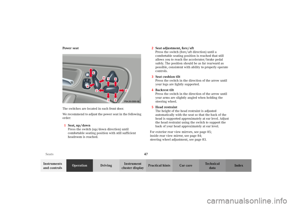
The switches are located in each front door.
We recommend to adjust the power seat in the following
order:
1Seat, up / down
Press the switch (up / down direction) until
comfortable seating position with still sufficient
headroom is reached.2Seat adjustment, fore / aft
Press the switch (fore / aft direction) until a
comfortable seating position is reached that still
allows you to reach the accelerator / brake pedal
safely. The position should be as far rearward as
possible, consistent with ability to properly operate
controls.
3Seat cushion tilt
Press the switch in the direction of the arrow until
your legs are lightly supported.
4Backrest tilt
Press the switch in the direction of the arrow until
your arms are slightly angled when holding the
steering wheel.
5Head restraint
The height of the head restraint is adjusted
automatically with the seat so that the back of the
head is supported approximately at ear level. Adjust
the head restraint using the switch to support the
back of your head approximately at ear level.
For exterior rear view mirrors, see page 85;
inside rear view mirror, see page 84;
steering wheel adjustment, see page 83.
S203.book Seite 47 Freitag, 19. Oktober 2001 1:25 13
Page 96 of 390
93 Instrument cluster
Te ch n i c a l
data Instruments
and controlsOperationDrivingInstrument
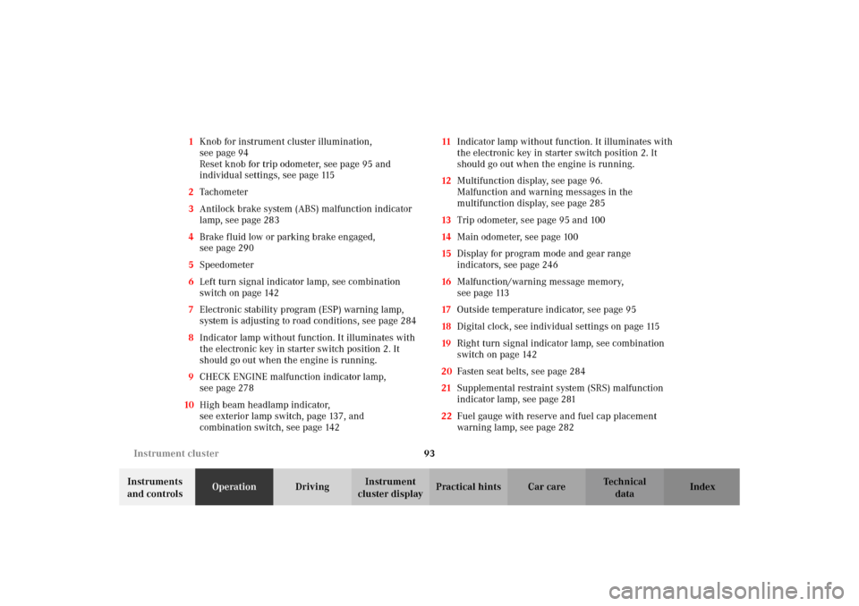
cluster displayPractical hints Car care Index 1Knob for instrument cluster illumination,
seepage94
Reset knob for trip odometer, see page 95 and
individual settings, see page 115
2Tachometer
3Antilock brake system (ABS) malfunction indicator
lamp, see page 283
4Brake fluid low or parking brake engaged,
seepage290
5Speedometer
6Left turn signal indicator lamp, see combination
switch on page 142
7Electronic stability program (ESP) warning lamp,
system is adjusting to road conditions, see page 284
8Indicator lamp without function. It illuminates with
the electronic key in starter switch position 2. It
should go out when the engine is running.
9CHECK ENGINE malfunction indicator lamp,
seepage278
10High beam headlamp indicator,
see exterior lamp switch, page 137, and
combination switch, see page 14211Indicator lamp without function. It illuminates with
the electronic key in starter switch position 2. It
should go out when the engine is running.
12Multifunction display, see page 96.
Malfunction and warning messages in the
multifunction display, see page 285
13Trip odometer, see page 95 and 100
14Main odometer, see page 100
15Display for program mode and gear range
indicators, see page 246
16Malfunction/warning message memory,
seepage113
17Outside temperature indicator, see page 95
18Digital clock, see individual settings on page 115
19Right turn signal indicator lamp, see combination
switch on page 142
20Fasten seat belts, see page 284
21S upplem ental restraint system (SRS) m alfunction
indicator lamp, see page 281
22Fuel gauge with reserve and fuel cap placement
warning lamp, see page 282
S203.book Seite 93 Freitag, 19. Oktober 2001 1:25 13
Page 203 of 390
200 Interior equipment
Te ch n i c a l
data Instruments
and controlsOperationDrivingInstrument
cluster displayPractical hints Car care Index
Ashtrays
Center console
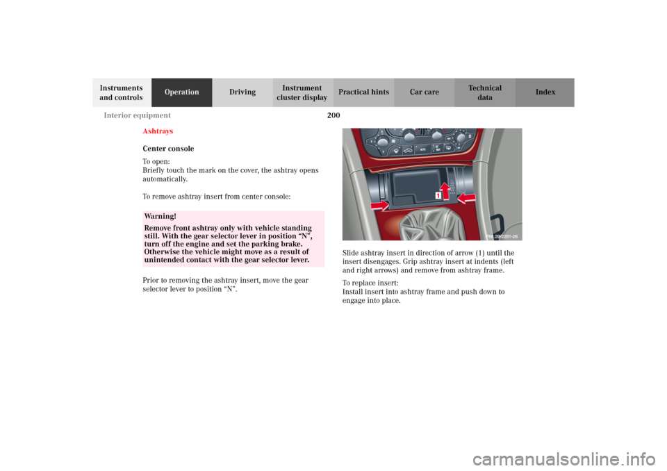
To o pen :
Briefly touch the mark on the cover, the ashtray opens
automatically.
To remove ashtray insert from center console:
Prior to removing the ashtray insert, move the gear
selector lever to position “N”.Slide ashtray insert in direction of arrow (1) until the
insert disengages. Grip ashtray insert at indents (left
and right arrows) and remove from ashtray frame.
To replace insert:
Install insert into ashtray frame and push down to
engage into place.
Wa r n i n g !
Remove front ashtray only with vehicle standing
still. With the gear selector lever in position “N”,
turn off the engine and set the parking brake.
Otherwise the vehicle might move as a result of
unintended contact with the gear selector lever.
S203.book Seite 200 Freitag, 19. Oktober 2001 1:25 13
Page 228 of 390
225 Contents - Driving
Te ch n i c a l
data Instruments
and controlsOperationDrivingInstrument
cluster displayPractical hints Car care Index
DrivingControl and operation of
radio transmitters .....................226
The first 1 000 miles
(1 500 km) .................................227
Maintenance ...................................227
Tele Aid ...........................................228
Catalytic converter ........................238
Emission control ............................239
Starter switch .................................240
Starting and turning off
the engine ..................................242
Automatic transmission ...............243
Parking brake .................................252Driving instructions ...................... 253
Drive sensibly – Save Fuel ....... 253
Drinking and driving ................ 253
Pedals .......................................... 253
Power assistance ........................ 254
Brakes .......................................... 254
Driving off ................................... 255
Parking ........................................ 256
Tires ............................................. 257
Snow chains ............................... 259
Winter driving
instructions ................................ 260
Deep water .................................. 262
Passenger compartment ........... 263
Traveling abroad ........................ 263Cruise control .................................264
Brake assist system (BAS) ............267
Antilock brake system
(ABS) ...........................................268
Electronic stability program
(ESP) ...........................................270
What you should know
at the gas station ....................... 274
Check regularly and
before a long trip ...................... 276
S203.book Seite 225 Freitag, 19. Oktober 2001 1:25 13
Page 230 of 390
227 The first 1 000 miles
Te ch n i c a l
data Instruments
and controlsOperationDrivingInstrument
cluster displayPractical hints Car care Index The first 1 000 miles (1 500 km)
The more cautiously you treat your vehicle during the
break-in period, the more satisfied you will be with its
performance later on. Therefore, drive your vehicle
during the first 1 000 miles (1 500 km) at moderate
vehicle and engine speeds.
During this period, avoid heavy loads (full throttle
driving) and excessive engine speeds.
Avoid accelerating by kickdown. It is not recommended
to brake t he vehicle by man ually shif tin g to a lower gear.
We recommend that you select positions “3”, “2” or “1”
only at moderate speeds (for hill driving).
After 1 000 miles (1 500 km) speeds may be gradually
increased to the permissible maximum.Maintenance
We strongly recommend that you have your vehicle
serviced by your authorized Mercedes-Benz Center, in
accordance with the Service Booklet at the times called
for by the FSS.
Failure to have the vehicle maintained in accordance
with the Service Booklet at the designated times /
mileage may result in vehicle damage not covered by
the Mercedes-Benz Limited Warranty.
For information on the Flexible service system (FSS),
see page 132.
S203.book Seite 227 Freitag, 19. Oktober 2001 1:25 13
Page 243 of 390
240 Starter switch
Te ch n i c a l
data Instruments
and controlsOperationDrivingInstrument
cluster displayPractical hints Car care Index
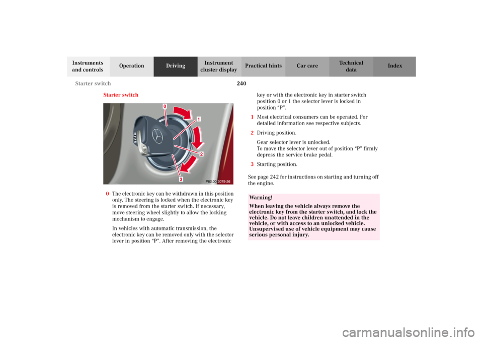
Starter switch
0The electronic key can be withdrawn in this position
only. The steering is locked when the electronic key
is removed from the starter switch. If necessary,
move steering wheel slightly to allow the locking
mechanism to engage.
In vehicles with automatic transmission, the
electronic key can be removed only with the selector
lever in position “P”. After removing the electronic key or with the electronic key in starter switch
position 0 or 1 the selector lever is locked in
position “P”.
1Most electrical consumers can be operated. For
detailed information see respective subjects.
2Driving position.
Gear selector lever is unlocked.
To move the selector lever out of position “P” firmly
depress the service brake pedal.
3Starting position.
See page 242 for instructions on starting and turning off
the engine.
Wa r n i n g !
When leaving the vehicle always remove the
electronic key from the starter switch, and lock the
vehicle. Do not leave children unattended in the
vehicle, or with access to an unlocked vehicle.
Unsupervised use of vehicle equipment may cause
serious personal injury.
S203.book Seite 240 Freitag, 19. Oktober 2001 1:25 13
Page 245 of 390
242 Starting and turning off the enginge
Te ch n i c a l
data Instruments
and controlsOperationDrivingInstrument
cluster displayPractical hints Car care Index
Starting and turning off the engine
Before starting
Ensure that parking brake is engaged and that selector
lever is in position “P” or “N”. Turn electronic key in
starter switch to position 2.
Starting
Do n ot de pr ess accelerato r. B rie f ly turn electron ic key in
starter switch clockwise to the stop and release. The
starter will engage until the engine is running.
If engine will not run, and the starting procedure stops,
turn electronic key completely to the left and repeat
starting the engine.
After several unsuccessful attempts, have the system
checked at the nearest authorized Mercedes-Benz
Center.Important!
Due to the installed starter non-repeat feature, the
electronic key must be turned completely to the left
before attempting to start the engine again.
In areas where temperatures frequently drop below -4
°F
(-20
°C) we recommend that an engine block heater be
installed. Your authorized Mercedes-Benz Center will
advise you on this subject, see page 261.
Turning off
Turn the electronic key in the starter switch to
position 0 to turn off the engine.
The electronic key can only be removed with the
selector lever in position “P”.
S203.book Seite 242 Freitag, 19. Oktober 2001 1:25 13