Hood MERCEDES-BENZ CL500 2002 C215 Owner's Manual
[x] Cancel search | Manufacturer: MERCEDES-BENZ, Model Year: 2002, Model line: CL500, Model: MERCEDES-BENZ CL500 2002 C215Pages: 430
Page 7 of 430

4 Contents
Instrument cluster displayMalfunction and indicator
lamps in the
instrument cluster ....................296
On-board
diagnostic system .......................296
Check engine malfunction
indicator lamp .............................296
Brake warning lamp ..................298
Supplemental
restraint system
(SRS) indicator lamp ..................299
Fuel reserve warning .................299
ABS malfunction
indicator lamp .............................300
Electronic stabilityprogram
(ESP) — warning lamp ............... 301
Distronic (DTR) —
warning lamp .............................. 301
Seat belt nonusage
warning lamp ..............................302
Malfunction and indicator
lamp in the center console ......302
AIRBAG OFF indicator lamp .....302Malfunction and
warning messages in the
multifunction display .............. 303
DISPLAY DEFECTIVE
(engine control unit) ................. 304
DISPLAY DEFECTIVE
(several systems) ....................... 304
BATTERY /ALTERNATOR ......... 305
ENTRY POSITION ...................... 306
BRAKE ASSIST ........................... 306
BRAKE PAD WEAR .................... 307
BRAKE FLUID ............................ 307
PARKING BRAKE ....................... 308
TRUNK OPEN ............................. 308
ELEC. STABIL. PROG.
(Electronic stability program) . 309
COOLANT (coolant level) .......... 310
COOLANT
(coolant temperature) ................ 311
LIGHTING SYSTEM ....................312
LAMP SENSOR ............................ 314
SEAT BELT SYSTEM ................... 314
TELEPHONE – FUNCTION ........ 315
CRUISE CONTROL ...................... 315ACTIVE BODY CONTROL
(ABC) ............................................ 316
TIRE PRESSURE ......................... 318
ENGINE OIL LEVEL ...................320
SEAT BACKREST ........................ 321
KEY ...............................................322
DOOR ...........................................322
HOOD ...........................................323
TELE AID .....................................323
WASHER FLUID .........................326
DISTRONIC (DTR) ......................327
Practical hintsFirst aid kit .....................................330
Fuses ................................................ 331
Shelf below rear window ..............333
Hood .................................................334
Checking engine oil level .............337
Automatic transmission
fluid level ...................................338
Active body control
(ABC) fluid level ........................338
Coolant level ...................................339
Adding coolant ...........................339
J_OM_215.book Seite 4 Mittwoch, 30. Mai 2001 2:01 14
Page 26 of 430
23 Instruments and controls
Te ch n i c a l
data Instruments
and controlsOperation DrivingInstrument
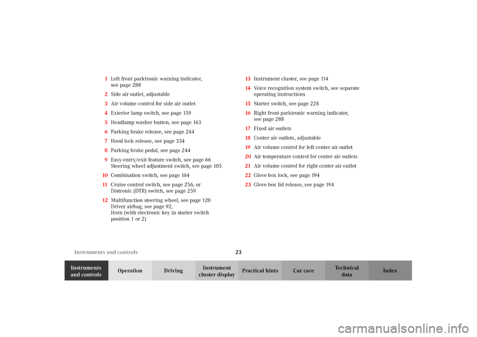
cluster displayPractical hints Car care Index 1Left front parktronic warning indicator,
seepage288
2Side air outlet, adjustable
3Air volume control for side air outlet
4Exterior lamp switch, see page 159
5Headlamp washer button, see page 163
6Parking brake release, see page 244
7Hood lock release, see page 334
8Parking brake pedal, see page 244
9Easy-entry/exit feature switch, see page 66
Steering wheel adjustment switch, see page 105
10Combination switch, see page 164
11Cruise control switch, see page 256, or
Distronic (DTR) switch, see page 259
12Multifunction steering wheel, see page 120
Driver airbag, see page 92,
Horn (with electronic key in starter switch
position 1 or 2)13Instrument cluster, seepage114
14Voice recognition system switch, see separate
operating instructions
15Starter switch, see page 228
16Right front parktronic warning indicator,
seepage288
17Fixed air outlets
18Center air outlets, adjustable
19Air volume control for left center air outlet
20Air temperature control for center air outlets
21Air volume control for right center air outlet
22Glove box lock, seepage194
23Glove box lid release, see page 194
J_OM_215.book Seite 23 Mittwoch, 30. Mai 2001 2:01 14
Page 65 of 430
62 Antitheft alarm system
Te ch n i c a l
data Instruments
and controlsOperationDrivingInstrument
cluster displayPractical hints Car care Index
Antitheft alarm system
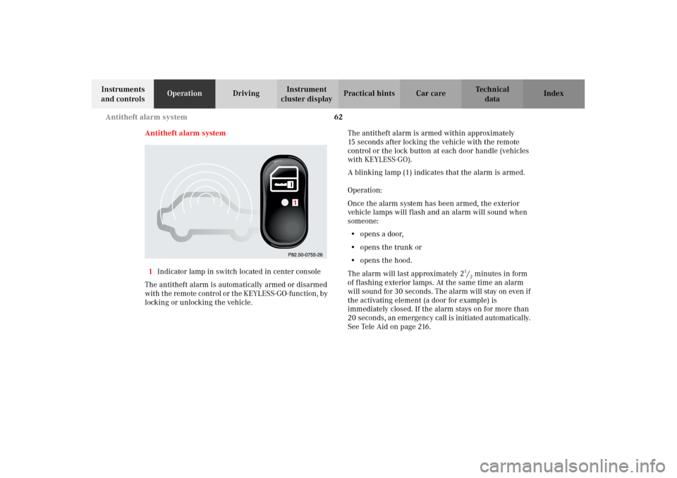
1Indicator lamp in switch located in center console
The antitheft alarm is automatically armed or disarmed
wit h t he re mote con tr ol or t he KEYL ESS- GO - fun ction , by
locking or unlocking the vehicle.The antitheft alarm is armed within approximately
15 seconds after locking the vehicle with the remote
control or the lock button at each door handle (vehicles
with KEYLESS-GO).
A blinking lamp (1) indicates that the alarm is armed.
Operation:
Once the alarm system has been armed, the exterior
vehicle lamps will flash and an alarm will sound when
someone:
•opens a door,
•opens the trunk or
•opens the hood.
The alarm will last approximately 2
1/2minutes in form
of flashing exterior lamps. At the same time an alarm
will sound for 30 seconds. The alarm will stay on even if
the activating element (a door for example) is
immediately closed. If the alarm stays on for more than
20 seconds, an emergency call is initiated automatically.
See Tele Aid on page 216.
J_OM_215.book Seite 62 Mittwoch, 30. Mai 2001 2:01 14
Page 89 of 430
86 Restraint systems
Te ch n i c a l
data Instruments
and controlsOperationDrivingInstrument
cluster displayPractical hints Car care Index
Operation of seat belts
The inertia reel stops the belt from unwinding during
sudden stops or when quickly pulling on the belt.
The locking function of the reel may be checked by
quickly pulling out the belt.
Caution!
For safety reasons, avoid adjusting the seat or seat back
into positions which could affect the correct seat belt
positioning.
Unfastening of seat belts
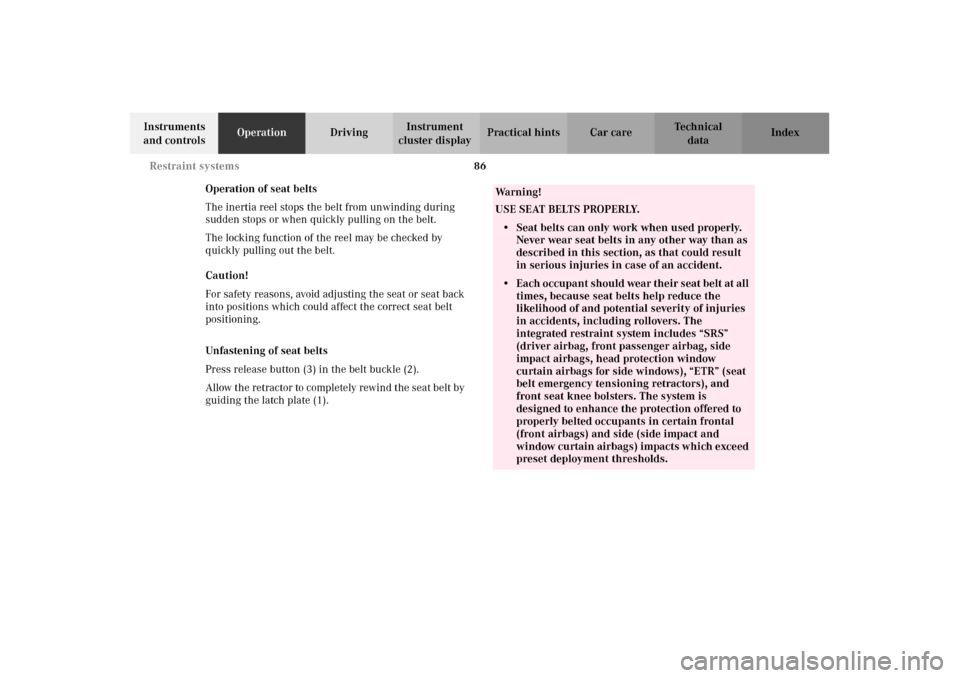
Press release button (3) in the belt buckle (2).
Allow the retractor to completely rewind the seat belt by
guiding the latch plate (1).
Wa r n i n g !
USE SEAT BELTS PROPERLY.• Seat belts can only work when used properly.
Never wear seat belts in any other way than as
described in this section, as that could result
in serious injuries in case of an accident.• Each occupant should wear their seat belt at all
times, because seat belts help reduce the
likelihood of and potential severity of injuries
in accidents, including rollovers. The
integrated restraint system includes “SRS”
(driver airbag, front passenger airbag, side
impact airbags, head protection window
curtain airbags for side windows), “ETR” (seat
belt emergency tensioning retractors), and
front seat knee bolsters. The system is
designed to enhance the protection offered to
properly belted occupants in certain frontal
(front airbags) and side (side impact and
window curtain airbags) impacts which exceed
preset deployment thresholds.
J_OM_215.book Seite 86 Mittwoch, 30. Mai 2001 2:01 14
Page 120 of 430
117 Instrument cluster
Te ch n i c a l
data Instruments
and controlsOperationDrivingInstrument
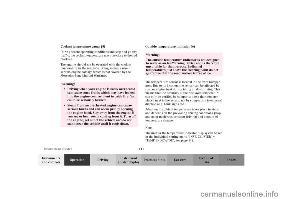
cluster displayPractical hints Car care Index Coolant temperature gauge (5)
During severe operating conditions and stop-and-go city
traffic, the coolant temperature may rise close to the red
marking.
The engine should not be operated with the coolant
temperature in the red zone. Doing so may cause
serious engine damage which is not covered by the
Mercedes-Benz Limited Warranty.Outside temperature indicator (6)
The temperature sensor is located in the front bumper
area. Due to its location, the sensor can be affected by
road or engine heat during idling or slow driving. This
means that the accuracy of the displayed temperature
can only be verified by comparison to a thermometer
placed next to the sensor, not by comparison to external
displays (e.g. bank signs etc.).
Adaption to ambient temperature takes place in steps
and depends on the prevailing driving conditions (stop-
and-go or moderate, constant driving) and amount of
temperature change.
Note:
The unit for the temperature indicator display can be set
in the individual setting menu “INST. CLUSTER” –
“TEMP. INDICATOR”, see page 142.
Wa r n i n g !
• Driving when your engine is badly overheated
can cause some fluids which may have leaked
into the engine compartment to catch fire. You
could be seriously burned.• Steam from an overheated engine can cause
serious burns and can occur just by opening
the engine hood. Stay away from the engine if
you see or hear steam coming from it. Turn off
the engine, get out of the vehicle and do not
stand near the vehicle until it cools down.
Wa r n i n g !
The outside temperature indicator is not designed
to serve as an Ice-Warning Device and is therefore
unsuitable for that purpose. Indicated
temperatures just above the freezing point do not
guarantee that the road surface is free of ice.
J_OM_215.book Seite 117 Mittwoch, 30. Mai 2001 2:01 14
Page 270 of 430
267 Driving systems
Te ch n i c a l
data Instruments
and controlsOperationDrivingInstrument
cluster displayPractical hints Car care Index Additional driving hints
Important!
When starting the engine, Distronic goes through an
initialization and self-test phase – this can take up to
2minutes.
The most likely cause for a malfunctioning system is a
by a dirty sensor (located behind the hood grille),
especially at times of snow and ice or heavy rain. In
such a case, Distronic will switch off, and the message
“DISTRONIC – CLEAN SENSOR!” appears in the
multifunction display.
For cleaning and care of the Distronic sensor see
page 384.
Restart the engine after cleaning the sensor.
The following are some sample situations which may
influence the functions of Distronic.
Wa r n i n g !
Distronic works to maintain the speed selected by
the driver unless a moving obstacle proceeding
directly ahead of it in the same travel direction is
detected (e.g. following another vehicle ahead at a
distance set by Distronic). This means that:• your vehicle can pass another vehicle after you
change lanes,• while in a sharp turn or if the vehicle in front
is in a sharp turn, Distronic could lose sight of
a vehicle traveling in front of it, then your
vehicle could accelerate to the previously
selected speed.Distronic regulates only the distance between your
vehicle and those directly ahead, but does not
register stationary objects in the roadway, e.g.:
• a stopped vehicle in a traffic jam.
• a disabled vehicle.
• an oncoming vehicle.
The driver must always be on the alert and observe
all traffic and intercede with steering and braking
inputs as necessary.Wa r n i n g !
Distronic should not be used in snowy or icy road
conditions.
J_OM_215.book Seite 267 Mittwoch, 30. Mai 2001 2:01 14
Page 279 of 430
276 Driving systems
Te ch n i c a l
data Instruments
and controlsOperationDrivingInstrument
cluster displayPractical hints Car care Index
Antilock brake system (ABS)
Important!
The ABS improves steering control of the vehicle during
hard braking maneuvers.
The ABS prevents the wheels from locking up above a
vehicle speed of approximately 5 mph (8 km/h)
independent of road surface conditions.At the instant one of the wheels is about to lock up, a
slight pulsation can be felt in the brake pedal,
indicating that the ABS is in the regulating mode. Keep
firm and steady pressure on the brake pedal while
experiencing the pulsation.
Continuous steady brake pedal pressure results in
applying the advantages of the ABS, namely braking
power and ability to steer the vehicle.
In the case of an emergency brake maneuver keep
continuous full pressure on the brake pedal. In this
manner only can the ABS be most effective.
On slippery road surfaces, the ABS will respond even
with light brake pedal pressure because of the
increased likelihood of locking wheels. The pulsating
brake pedal can be an indication of hazardous road
conditions and functions as a reminder to take extra
care while driving.
Wa r n i n g !
Do not pump the brake pedal, rather use firm,
steady brake pedal pressure. Pumping the brake
pedal defeats the purpose for ABS and significantly
reduces braking effectiveness.
J_OM_215.book Seite 276 Mittwoch, 30. Mai 2001 2:01 14
Page 296 of 430
293 What you should know at the gas station
Te ch n i c a l
data Instruments
and controlsOperationDrivingInstrument
cluster displayPractical hints Car care Index Tire pressure
For tire pressure, refer to tire pressure label inside the
fuel filler flap. See page 351 for further details.
Air conditioner
R-134a refrigerant and special PAG lubricant, refer to
“Technical Data”.
Spark plugs
Approved spark plugs, refer to page 397.
Windshield cleaning
To prevent damage to the engine hood, the windshield
wipers must not be folded forward in parked position.
See page 386 for cleaning the windshield.Bulbs
Low beam: Xenon,
high beam: H7 (55 W)
fog lamps: H1 (55 W),
turn signal lamps, front: 1156 NA bulb,
parking and standing lamps, front: H 6W
side marker lamps, front: W 5 W/4 cp,
turn signal lamps, rear: 1156 NA bulb,
tail and parking lamp: 67/4 cp,
tail, parking and rear fog lamp, driver’s side: P 21/4 W,
tail, parking, standing and
side marker lamp: 67/4 cp,
backup lamps: 1160/32 cp,
license plate lamps: C 5 W/4 cp
J_OM_215.book Seite 293 Mittwoch, 30. Mai 2001 2:01 14
Page 297 of 430
294 Check regularly and before a long trip
Te ch n i c a l
data Instruments
and controlsOperationDrivingInstrument
cluster displayPractical hints Car care Index
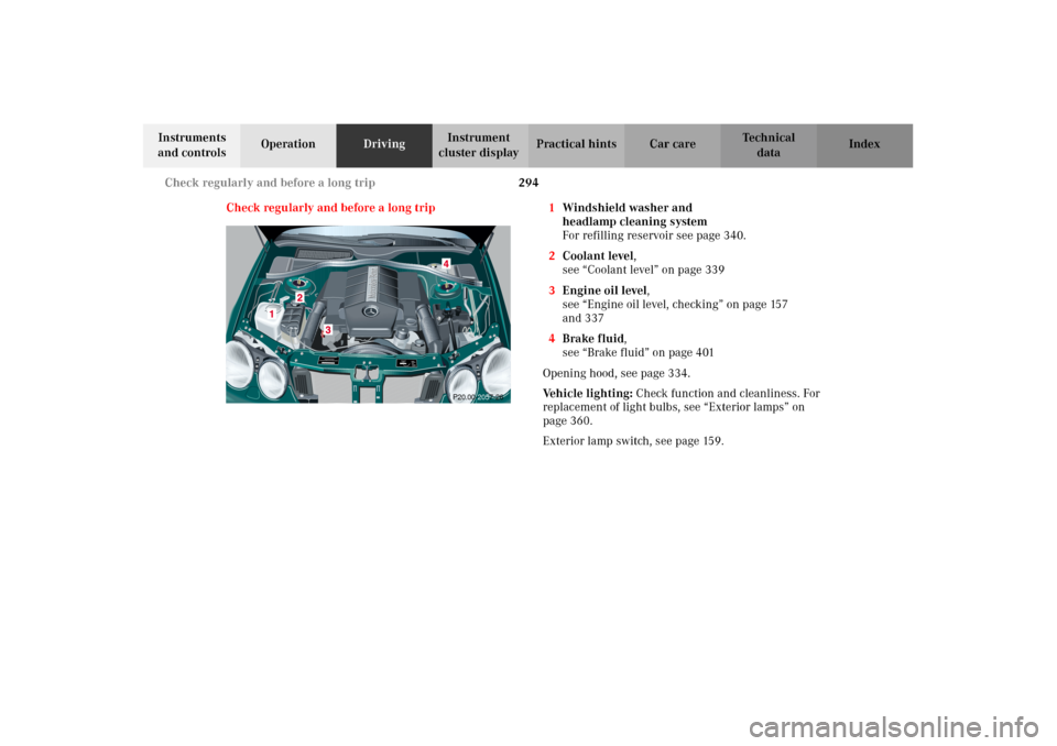
Check regularly and before a long trip 1Windshield washer and
headlamp cleaning system
For refilling reservoir see page 340.
2Coolant level,
see “Coolant level” on page 339
3Engine oil level,
see “Engine oil level, checking” on page 157
and 337
4Brake fluid,
see “Brake fluid” on page 401
Opening hood, see page 334.
Ve h i c l e l i g h t i n g : Check function and cleanliness. For
replacement of light bulbs, see “Exterior lamps” on
page 360.
Exterior lamp switch, see page 159.
P20.00-2057-26
J_OM_215.book Seite 294 Mittwoch, 30. Mai 2001 2:01 14
Page 298 of 430
295 Contents - Instrument cluster display
Te ch n i c a l
data Instruments
and controlsOperation DrivingInstrument
cluster displayPractical hints Car care Index
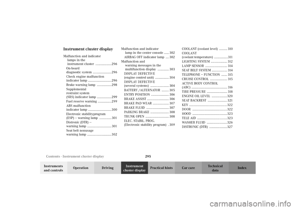
Instrument cluster displayMalfunction and indicator
lamps in the
instrument cluster ....................296
On-board
diagnostic system .......................296
Check engine malfunction
indicator lamp .............................296
Brake warning lamp ..................298
Supplemental
restraint system
(SRS) indicator lamp ..................299
Fuel reserve warning .................299
ABS malfunction
indicator lamp .............................300
Electronic stabilityprogram
(ESP) — warning lamp ............... 301
Distronic (DTR) —
warning lamp .............................. 301
Seat belt nonusage
warning lamp ..............................302Malfunction and indicator
lamp in the center console ...... 302
AIRBAG OFF indicator lamp .... 302
Malfunction and
warning messages in the
multifunction display .............. 303
DISPLAY DEFECTIVE
(engine control unit) ................. 304
DISPLAY DEFECTIVE
(several systems) ....................... 304
BATTERY /ALTERNATOR ......... 305
ENTRY POSITION ...................... 306
BRAKE ASSIST ........................... 306
BRAKE PAD WEAR .................... 307
BRAKE FLUID ............................ 307
PARKING BRAKE ....................... 308
TRUNK OPEN ............................. 308
ELEC. STABIL. PROG.
(Electronic stability program) . 309COOLANT (coolant level) .......... 310
COOLANT
(coolant temperature) .................311
LIGHTING SYSTEM .................... 312
LAMP SENSOR ........................... 314
SEAT BELT SYSTEM ................... 314
TELEPHONE – FUNCTION ....... 315
CRUISE CONTROL ..................... 315
ACTIVE BODY CONTROL
(ABC) ............................................ 316
TIRE PRESSURE ......................... 318
ENGINE OIL LEVEL ...................320
SEAT BACKREST ........................ 321
KEY ...............................................322
DOOR ...........................................322
HOOD ...........................................323
TELE AID .....................................323
WASHER FLUID .........................326
DISTRONIC (DTR) ......................327
J_OM_215.book Seite 295 Mittwoch, 30. Mai 2001 2:01 14