MERCEDES-BENZ CL55AMG 2001 C215 Owner's Manual
Manufacturer: MERCEDES-BENZ, Model Year: 2001, Model line: CL55AMG, Model: MERCEDES-BENZ CL55AMG 2001 C215Pages: 424, PDF Size: 27.87 MB
Page 281 of 424
276 Driving systems
Te ch n ica l
data Instruments
and controlsOperationDrivingInstrument
cluster displayPractical hints Car care Index
Level control system
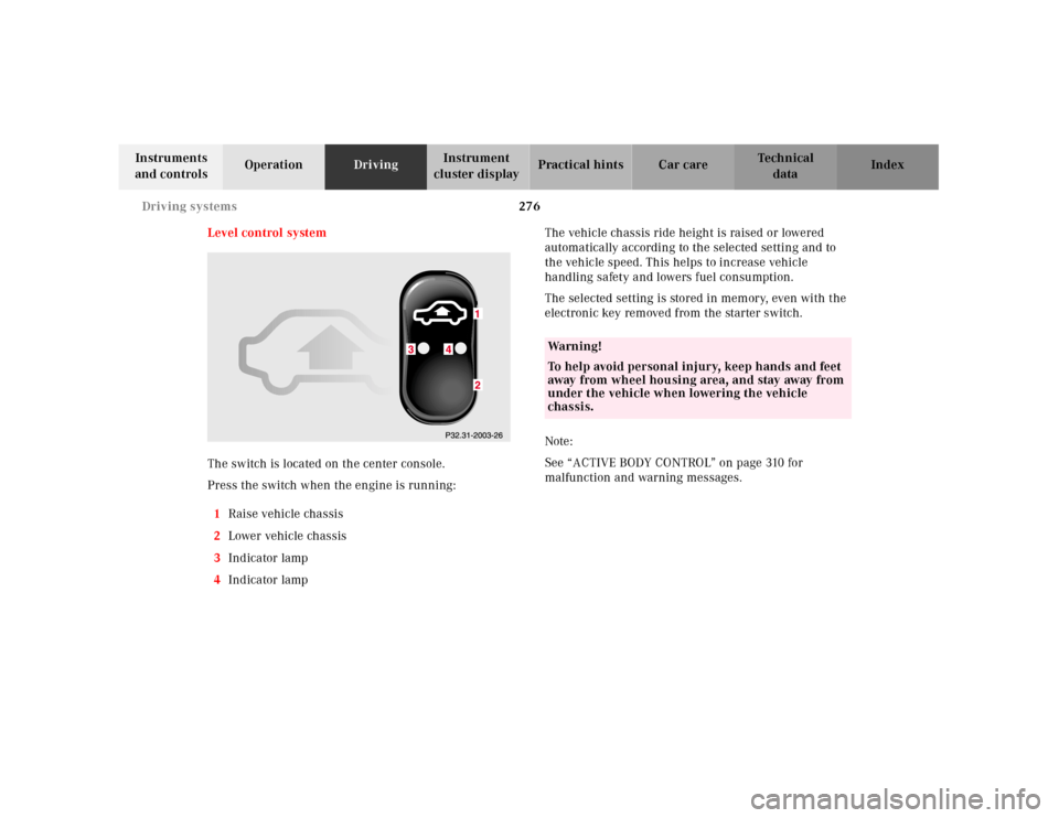
The switch is located on the center console.
Press the switch when the engine is running:
1Raise vehicle chassis
2Lower vehicle chassis
3Indicator lamp
4Indicator lampThe vehicle chassis ride height is raised or lowered
automatically according to the selected setting and to
the vehicle speed. This helps to increase vehicle
handling safety and lowers fuel consumption.
The selected setting is stored in memory, even with the
electronic key removed from the starter switch.
Note:
See “ACTIVE BODY CONTROL” on page 310 for
malfunction and warning messages.
Wa r n i n g !
To help avoid personal injury, keep hands and feet
away from wheel housing area, and stay away from
under the vehicle when lowering the vehicle
chassis.
Page 282 of 424
277 Driving systems
Te ch n ica l
data Instruments
and controlsOperationDrivingInstrument
cluster displayPractical hints Car care Index Level control switch positions
Normal level – indicator lamps (3, 4) are not
illuminated. To change from raised level options I or II,
press lower half of switch (2) once respectively twice.
Raise level, option I – indicator lamp (3) is illuminated.
To change from normal level, press upper half (1) of
switch.
To change from raised level, option II, press lower
half (2) of switch.
Raised level, option 2 – indicator lamps (3, 4) are
illuminated.
To change from normal level or raised level, option I,
press upper half (1) of switch once respectively twice.Normal level
Used for normal operation of the vehicle.
Speed dependent lowering of vehicle chassis
(approximate values):
•between 0 mph (0 km/h) and 35 mph (60 km/h)
– none
•between 35 mph (60 km/h) and 85 mph (140 km/h)
– lowered progressively by approx. 7/16inch (11 mm)
Page 283 of 424
278 Driving systems
Te ch n ica l
data Instruments
and controlsOperationDrivingInstrument
cluster displayPractical hints Car care Index
Raised level, option I
This setting should be used when road surface
conditions are rough and must be used when driving
with snow chains mounted.
Important!
Driving with snow chains requires increased space
between tire and wheel housing. Refer to page 245 for
driving with snow chains.
Speed dependent lowering of vehicle chassis
(approximate values):
•at standstill – raised by approx. one half inch
(14 mm)
•between 35 mph (60 km/h) and 100 mph
(160 km/h) – lowered progressively by approx.
one half inch (14 mm)Raised level, option II
This setting should be used when road surface
conditions are very rough for increased ground
clearance.
Speed dependent lowering of vehicle chassis
(approximate values):
•at standstill - raised by approx. one inch (24 mm)
•between 0 mph (0 km/h) and 35 mph (6o km/h) -
lowered progressively by approx. 3/8inch (10 mm)
•between 35 mph (60 km/h) and 100 mph
(160 km/h) – lowered progressively by additional
approx. one half inch (14 mm)
Page 284 of 424
279 Parking system
Te ch n ica l
data Instruments
and controlsOperationDrivingInstrument
cluster displayPractical hints Car care Index Parking assist (Parktronic)
The Parktronic system assists the driver during parking
maneuvers. It visually and audibly indicates the relative
distance between the vehicle and an obstacle.
The front area of the vehicle is monitored when driving
forward. When reversing or with the gear selector lever
in position “N”, the front as well as the rear areas are
monitored.
With the electronic key in starter switch position 2,
Parktronic engages automatically at speeds up to
approximately 10 mph (15 km/h) and deactivates during
higher speeds.
Parktronic can be switched off by a control switch
located in the center console. It engages automatically
again when starting the engine.
See page 283 for parktronic switch.
Wa r n i n g !
Parktronic is a supplemental system. It is not
intended to nor does it replace the need for extreme
care. The responsibility during parking and other
critical maneuvers rests always with the driver.Special attention must be paid to objects having
smooth surfaces or low silhouettes (e.g. trailer
couplings, painted posts, or street curbs). Such
objects may not be detected by the system and can
damage the vehicle.The operational function of the Parktronic can be
affected by dirty sensors, especially at times of
snow and ice. See page 378 for notes on cleaning
the parktronic system sensors.Interference caused by other ultrasonic signals
(e.g. working jackhammers or the air brakes of
trucks) can cause the system to send erratic
indications, and should be taken into
consideration.
Page 285 of 424
280 Parking system
Te ch n ica l
data Instruments
and controlsOperationDrivingInstrument
cluster displayPractical hints Car care Index
Sensors
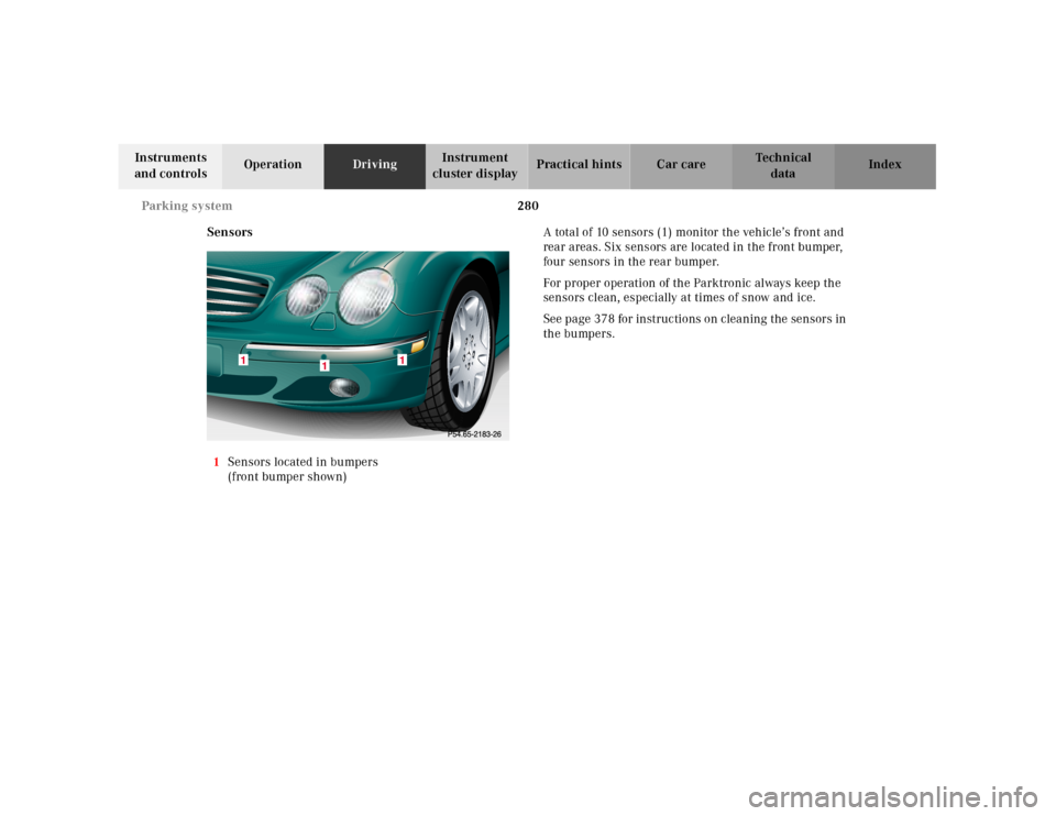
1Sensors located in bumpers
(front bumper shown)A total of 10 sensors (1) monitor the vehicle’s front and
rear areas. Six sensors are located in the front bumper,
four sensors in the rear bumper.
For proper operation of the Parktronic always keep the
sensors clean, especially at times of snow and ice.
See page 378 for instructions on cleaning the sensors in
the bumpers.
1
1
1
Page 286 of 424
281 Parking system
Te ch n ica l
data Instruments
and controlsOperationDrivingInstrument
cluster displayPractical hints Car care Index Warning indicators
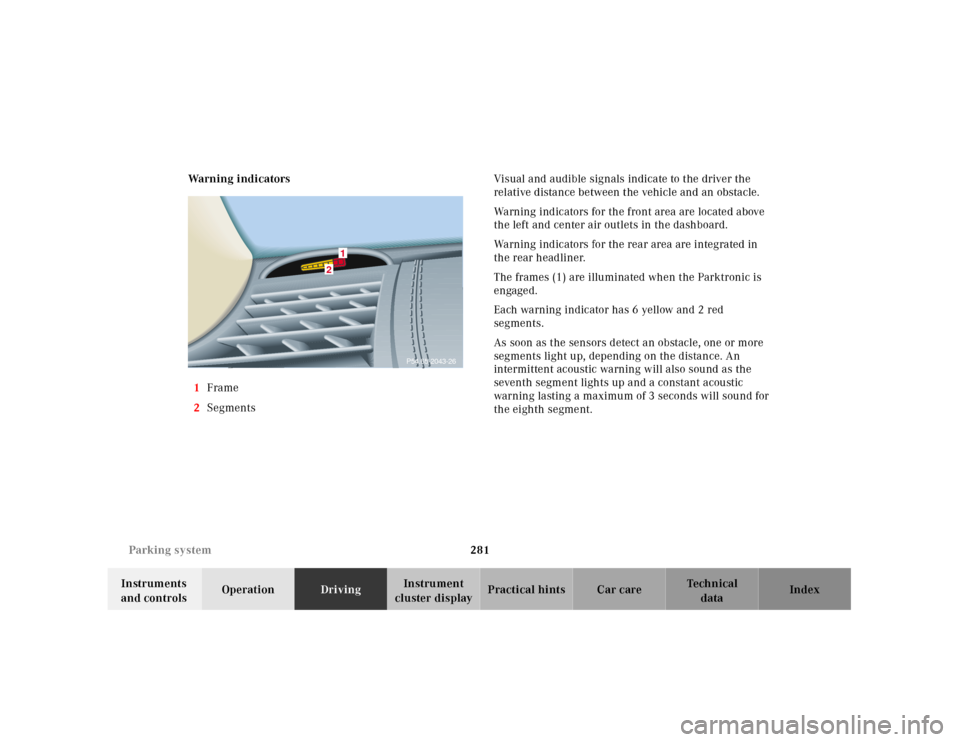
1Frame
2SegmentsVisual and audible signals indicate to the driver the
relative distance between the vehicle and an obstacle.
Warning indicators for the front area are located above
the left and center air outlets in the dashboard.
Warning indicators for the rear area are integrated in
the rear headliner.
The frames (1) are illuminated when the Parktronic is
engaged.
Each warning indicator has 6 yellow and 2 red
segments.
As soon as the sensors detect an obstacle, one or more
segments light up, depending on the distance. An
intermittent acoustic warning will also sound as the
seventh segment lights up and a constant acoustic
warning lasting a maximum of 3 seconds will sound for
the eighth segment.
2
1
P54.65-2043-26
Page 287 of 424
282 Parking system
Te ch n ica l
data Instruments
and controlsOperationDrivingInstrument
cluster displayPractical hints Car care Index
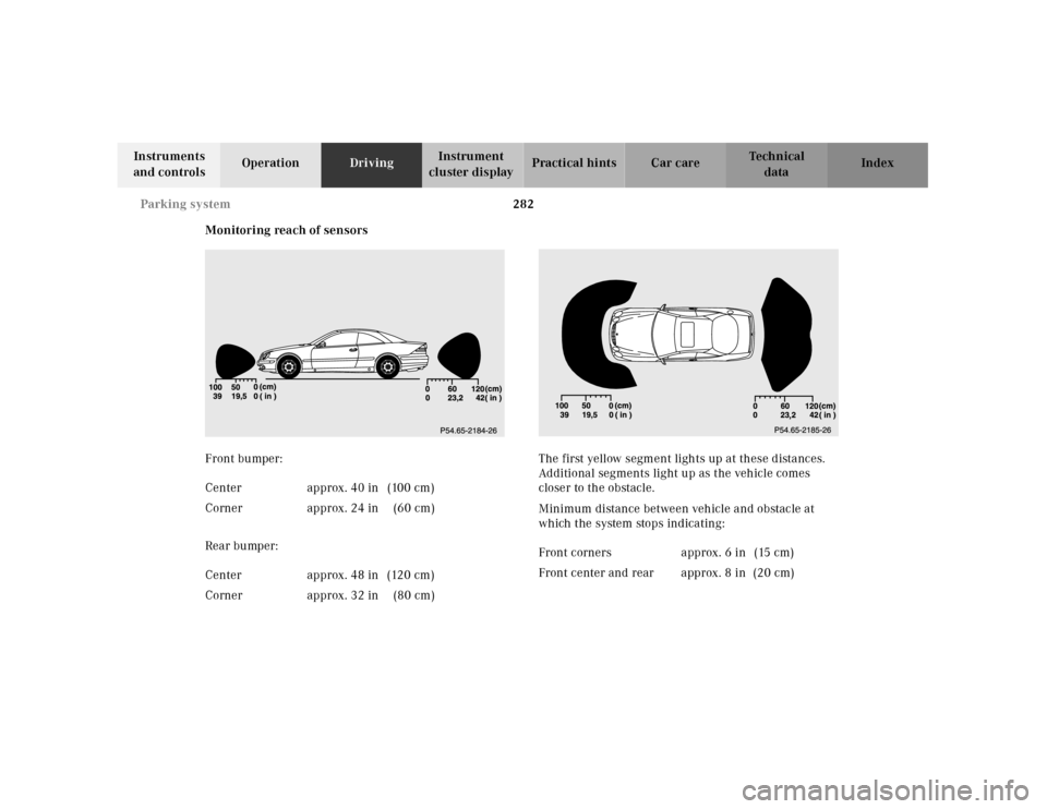
Monitoring reach of sensors
Front bumper:
Rear bumper:The first yellow segment lights up at these distances.
Additional segments light up as the vehicle comes
closer to the obstacle.
Minimum distance between vehicle and obstacle at
which the system stops indicating: Center approx. 40 in (100 cm)
Corner approx. 24 in (60 cm)
Center approx. 48 in (120 cm)
Corner approx. 32 in (80 cm)
Front corners approx. 6 in (15 cm)
Front center and rear approx. 8 in (20 cm)
Page 288 of 424
283 Parking system
Te ch n ica l
data Instruments
and controlsOperationDrivingInstrument
cluster displayPractical hints Car care Index The obstacle may not be recognized if outside the
shaded sensor field, and no longer be indicated when
approaching it any closer (warning indicators go out).
Parktronic malfunction
All red segments of the warning indicators light up, and
a warning sounds for 3 seconds, if Parktronic does not
function properly. The indicator lamp in the switch
lights up and the system switches off automatically!
A dirty sensor could be the reason. See page 378 for
instructions on cleaning the sensors in the bumpers.
After cleaning the sensors, turn electronic key in starter
switch to position 2. If the defect continues to be
displayed, have the system checked at your authorized
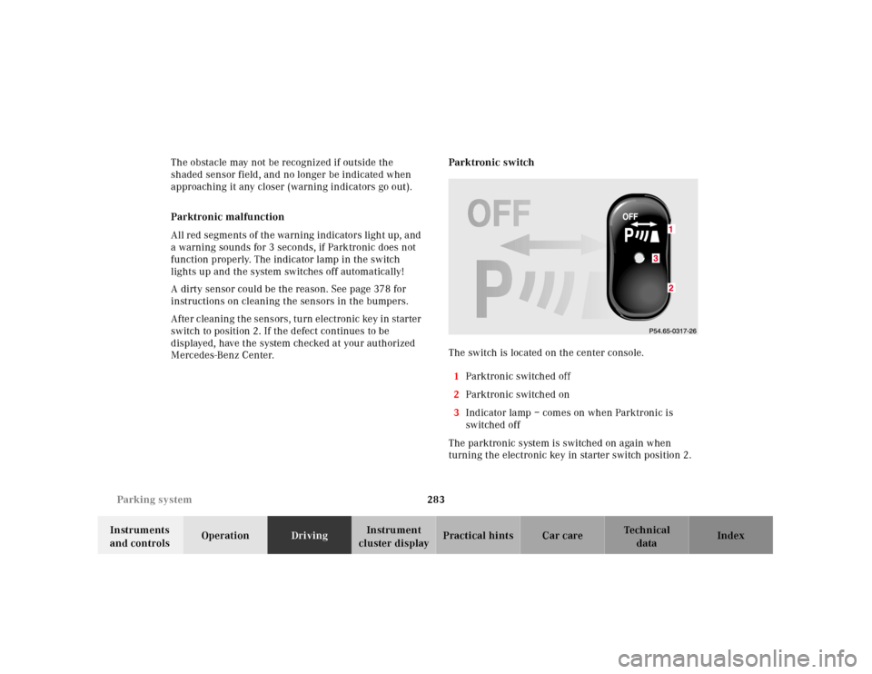
Mercedes-Benz Center.Parktronic switch
The switch is located on the center console.
1Parktronic switched off
2Parktronic switched on
3Indicator lamp – comes on when Parktronic is
switched off
The parktronic system is switched on again when
turning the electronic key in starter switch position 2.3
Page 289 of 424
284 What you should know at the gas station
Te ch n ica l
data Instruments
and controlsOperationDrivingInstrument
cluster displayPractical hints Car care Index
What you should know at the gas station
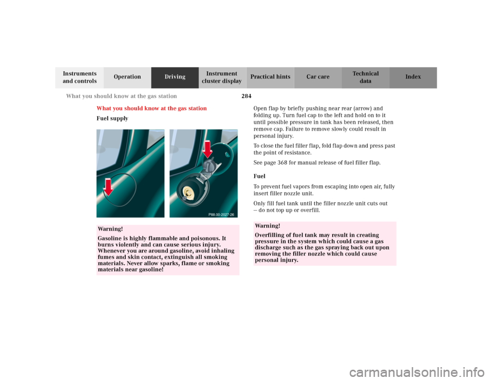
Fuel supplyOpen f lap by briefly pushing near rear (arrow) and
folding up. Turn fuel cap to the left and hold on to it
until possible pressure in tank has been released, then
remove cap. Failure to remove slowly could result in
personal injury.
To close t he fu el f iller f lap, fold f lap d ow n a nd press past
the point of resistance.
See page 368 for manual release of fuel filler flap.
Fuel
To prevent fuel vapors from escaping into open air, fully
insert filler nozzle unit.
Only fill fuel tank until the filler nozzle unit cuts out
— do not top up or overfill.
Wa r n i n g !
Gasoline is highly flammable and poisonous. It
burns violently and can cause serious injury.
Whenever you are around gasoline, avoid inhaling
fumes and skin contact, extinguish all smoking
materials. Never allow sparks, flame or smoking
materials near gasoline!
P88.00-2027-26
Wa r n i n g !
Overfilling of fuel tank may result in creating
pressure in the system which could cause a gas
discharge such as the gas spraying back out upon
removing the filler nozzle which could cause
personal injury.
Page 290 of 424
285 What you should know at the gas station
Te ch n ica l
data Instruments
and controlsOperationDrivingInstrument
cluster displayPractical hints Car care Index Leaving the engine running and the fuel cap open can
cause the “CHECK ENGINE” lamp to illuminate, see
page 290 for notes on the “CHECK ENGINE” lamp.
Fuel tank capacity approx. 23.2 US gal (88.0 l).
This includes approx. 2.9 US gal (11.0 l) reserve.
Use premium unleaded gasoline:
CL 500, CL 55 AMG:
Posted Octane Index 91 (Average of 96 RON/86 MON).
CL 600:
Posted Octane Index 93 (Average of 98 RON/88 MON).Engine oil
Checking oil level, see instructions on pages 154
and 331.
CL 500 and CL 55 AMG only:
Fill qu antity b etween u pper a nd l ower dipstick m arking
level: 2.1 US qt (2.0 l).
Recommended engine oils, see Approved Service
Products sheet.
Coolant
For normal replenishing, use water (potable water
quality). For further information refer to page 333.