rear view mirror MERCEDES-BENZ CL600 2001 C215 User Guide
[x] Cancel search | Manufacturer: MERCEDES-BENZ, Model Year: 2001, Model line: CL600, Model: MERCEDES-BENZ CL600 2001 C215Pages: 424, PDF Size: 27.87 MB
Page 113 of 424
110 Rear view mirrors
Te ch n ica l
data Instruments
and controlsOperationDrivingInstrument
cluster displayPractical hints Car care Index
Driver’s side exterior mirror, antiglare mode
Antiglare mode:
With the electronic key in starter switch position 2, the
mirror reflection brightness responds to changes in
light sensitivity.
With the gear selector lever in position “R”, or with the
interior light switched on, the mirror brightness does
not respond to changes in light sensitivity.
Note:
The automatic antiglare function does not react, if
incoming light is not aimed directly at sensors in the
mirror.Important!
Electrolyte drops coming into contact with the vehicle
paint finish can only be completely removed while in
their liquid state, by applying plenty of water.
Wa r n i n g !
In the case of an accident liquid electrolyte may
escape the mirror housing when the mirror glass
breaks.Electrolyte has an irritating effect. Do not allow the
liquid come into contact with eyes, skin, clothing,
or respiratory system. In cases it does, imm edi ately
flush affected area with water, and seek medical
help if necessary.
Page 114 of 424
111 Memory function
Te ch n ica l
data Instruments
and controlsOperationDrivingInstrument
cluster displayPractical hints Car care Index Memory function
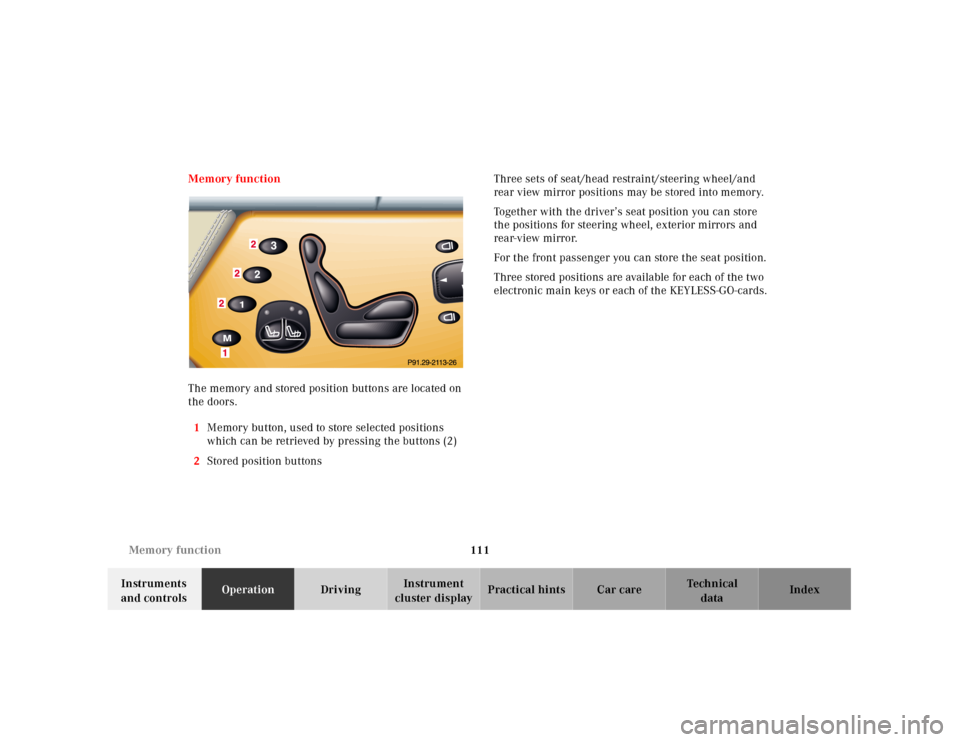
The memory and stored position buttons are located on
the doors.
1Memory button, used to store selected positions
which can be retrieved by pressing the buttons (2)
2Stored position buttonsThree sets of seat/head restraint/steering wheel/and
rear view mirror positions may be stored into memory.
Together with the driver’s seat position you can store
the positions for steering wheel, exterior mirrors and
rear-view mirror.
For the front passenger you can store the seat position.
Three stored positions are available for each of the two
electronic main keys or each of the KEYLESS-GO-cards.
Page 115 of 424
112 Memory function
Te ch n ica l
data Instruments
and controlsOperationDrivingInstrument
cluster displayPractical hints Car care Index
Storing positions into memory
Driver’s seat: with the electronic key in starter switch
position 1 or 2 or with the driver’s door open and the
electronic key inserted in the starter switch.
Front passenger seat: with electronic key in starter
switch position 1 or 2 or the passenger door open.
Adj ust t he seat a nd mul ticontou r back re st to t he d esired
position. You can also adjust the steering wheel, the
exterior mirrors electrically and the interior rear-view
mirror by hand for the driver’s seat. See page 67 for
front seat adjustment, page 107 for exterior mirror
adjustment and page 105 for steering wheel adjustment.
Push memory button “M”, release and push a stored
position button “1”,“ 2” or “3” within 3 seconds.Recalling positions from memory
To recall a seat/head restraint/steering wheel/inside
rear view mirror and exterior rear view mirror position,
push and hold button “1”, “2” or “3” until seat/head
restraint/steering wheel and exterior rear view mirror
movement has stopped.
The seat/head restraint/steering wheel/inside rear view
mirror and exterior rear view mirror movement stops
when the button is released.
Caution!
Do not operate the power seats using the memory
button if the backrest is in an excessively reclined
position. Doing so could cause damage to front or rear
seats.
First move backrest to an upright position.
Page 116 of 424
113 Memory function
Te ch n ica l
data Instruments
and controlsOperationDrivingInstrument
cluster displayPractical hints Car care Index Important!
Prior to operating the vehicle, the driver should check
and adjust if necessary the seat height, seat position
fore and aft, and backrest angle to insure adequate
control, reach and comfort. The head restraint should
also be adjusted for proper height. See also airbag
section for proper seat positioning.
In addition, also adjust the steering wheel to ensure
adequate control, reach, operation and comfort. Both the
inside and outside rear view mirrors should be adjusted
for adequate rearward vision.
Fasten seat belts. Infants and small children should be
seated in a properly secured restraint system that
complies with U.S. Federal Motor Vehicle Safety
Standard 213 and Canadian Motor Vehicle Safety
Standard 213.
All seat, head restraint, steering wheel, and rear view
mirror adjustments as well as fastening of seat belts
should be done before the vehicle is put into motion.
Wa r n i n g !
Children 12 years old and under must never ride in
the front seat, except in a Mercedes-Benz
authorized BabySmart
TM compatible child seat,
which operates with the BabySmart
TM system
installed in the vehicle to deactivate the passenger
front airbag when it is properly installed.
Otherwise they will be struck by the airbag when it
inflates in a crash. If this happens, serious or fatal
injury can result.
According to accident statistics, children are safer
when properly restrained in the rear seating
positions than in the front seating positions.
Infants and small children must ride in back seats
and be seated in an appropriate infant or child
restraint system, which is properly secured with
the vehicle’s seat belt, fully in accordance with the
child seat manufacturer’s instructions.A child’s risk of serious or fatal injuries is
significantly increased if the child restraints are
not properly secured in the vehicle and the child is
not properly secured in the child restraint.
Page 187 of 424
184 Interior equipment
Te ch n ica l
data Instruments
and controlsOperationDrivingInstrument
cluster displayPractical hints Car care Index
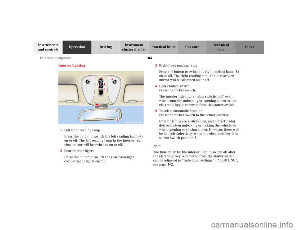
Interior lighting
1Left front reading lamp
Press the button to switch the left reading lamp (7)
on or off. The left reading lamp in the interior rear
view mirror will be switched on or off.
2Rear interior lights
Press the button to switch the rear passenger
compartment lights on/off.3Right front reading lamp
Press t he bu tton to sw itch t he rig ht read ing l amp (8)
on or off. The right reading lamp in the rear view
mirror will be switched on or off.
4Door contact switch:
Press the rocker switch.
The interior lighting remains switched off, even
when centrally unlocking or opening a door or the
electronic key is removed from the starter switch.
5To select automatic function:
Press the rocker switch to the center position.
Interior lamps are switched on, and off (soft fade)
delayed, when unlocking or locking the vehicle, or
when opening or closing a door. However, there will
be no (soft fade) delay when the electronic key is in
starter switch position 2.
Note:
The time delay for the interior light to switch off after
the electronic key is removed from the starter switch
can be adjusted in “Individual settings” – “LIGHTING”,
seepage142.
P68.00-2151-26
1
3
24
5
6
7
8
Page 188 of 424
185 Interior equipment
Te ch n ica l
data Instruments
and controlsOperationDrivingInstrument
cluster displayPractical hints Car care Index To prevent the vehicle battery from being discharged
with doors open, all interior lamps switch off after
approximately 5 minutes.
6 Interior lamps, front:
Press rocker switch in to switch front interior and
reading lamps on. The front interior lighting stays
on while the rocker switch is pressed in.
Switching off the front interior lighting:
Press rocker switch to position (4) or (5).
Courtesy lighting
The interior of your vehicle is equipped with various
different lighting installations to help you to orient
yourself better in the dark.
Entrance lamps, exit lamps
With exterior lamps on or electronic key in starter
switch position 1, the lamps in the door trays illuminate.
The lights will remain on for approximately 5 minutes if
the electronic key is in starter switch position 0 and
exterior lamps are switched off.Footwell lighting
With exterior lamps on, the driver and front passenger
footwell is illuminated.
Center console lighting
Turn the electronic key in the starter switch to
position 1. The center console is illuminated from the
rear-view mirror.
Door entry lamps
The appropriate entry lamp switches on if a door is
opened in darkness and if the interior lighting is
switched to automatic function.
The entry lamp switches off automatically when the
door is closed.
Page 206 of 424
203 Garage door opener
Te ch n ica l
data Instruments
and controlsOperationDrivingInstrument
cluster displayPractical hints Car care Index For operation in the USA only: This device complies
with Part 15, Subpart C, Section 209 of the FCC Rules.
Operation is subject to the following two conditions:
(1) This device may not cause harmful interference, and
(2) this device must accept any interference received,
including interference that may cause undesired
operation.
WARNING: Changes or modification not expressly
a p pr ove d by pa rt y r e s po n si b l e f or c o mpl ia n c e c o u l d vo i d
the user’s authority to operate the equipment.
Programming or reprogramming the integrated
remote control:
1. Turn electronic key in starter switch to position 1
or 2.
2. Hold the end of the hand-held transmitter of the
d evice you w ish to train approxim ately 2 to 5 inch es
(5 cm to 12 cm) away from the surface of the
integrated remote control located on the inside rear
view mirror, keeping the indicator lamp in view.3. Using both hands, simultaneously push the hand-
held transmitter button and the desired integrated
remote control button. Do not release the buttons
until completing step 4.
4. The indicator lamp on the integrated remote control
will flash, first slowly and then rapidly. When the
indicator lamp f lashes rapidly, both buttons may be
released (the rapid flashing lamp indicates
successful programming of the new frequency
signal). To program the remaining two buttons,
follow ste ps 1 through 4.
Note:
If, after repeated attempts, you do not successfully
program the integrated remote control device to learn
the signal of the hand-held transmitter, the garage door
opener could be equipped with the “rolling code
feature”.
Page 216 of 424
211 Tele Aid
Te ch n ica l
data Instruments
and controlsOperationDrivingInstrument
cluster displayPractical hints Car care Index Important!
Always make sure that the indicator lamps in the
“SOS” button, in the “Roadside Assistance” button and
in the “Information” button do not remain illuminated
constantly in red and the message “TELE AID – VISIT
WORKSHOP” is not displayed in the multifunction
display after the system self check.
If a malfunction is indicated as outlined above, have the
system checked at the nearest Mercedes-Benz Center as
soon as possible.
Emergency calls
An emergency call is initiated automatically:
•following an accident in which the Emergency
Tensioning Retractors (ETR’s) or airbags deploy,
•if the antitheft alarm or the tow away alarm stays on
for more than 20 seconds, see pages 62 and 64.
An emergency call can also be initiated manually by
opening the cover next to the inside rear view mirror
labeled “SOS”, then pressing the button (for longer than
2 seconds) located under the cover. See below for
instructions on initiating an emergency call manually.Once the emergency call is in progress, the indicator
lamp in the “SOS” button will begin to f lash. The
message “EMERGENCY CALL – CONNECTING CALL”
appears in the multifunction display. When the
connection is established, the message “EMERGENCY
CALL – CALL CONNECTED” appears in the
multifunction display. All information relevant to the
emergency, such as the location of the vehicle
(determined by the GPS satellite location system),
vehicle model, identification number and color are
generated.
A voice connection between the Response Center and
the occupants of the vehicle will be established
automatically soon after the emergency call has been
initiated. When a voice connection is established the
audio system mutes and the message “TELE AID –
EMERGENCY CALL ACTIVE” appears in the
multifunction display. The Response Center will attempt
to determine more precisely the nature of the accident
provided they can speak to an occupant of the vehicle.
Page 411 of 424
405 Index
Te ch n ica l
data Instruments
and controlsOperation DrivingInstrument
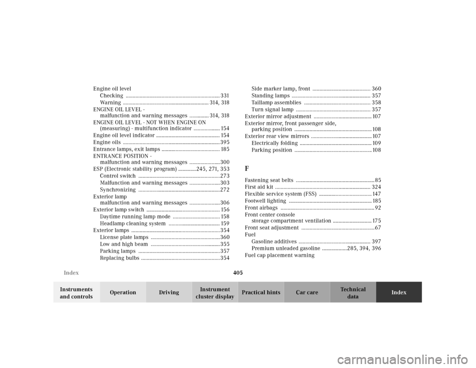
cluster displayPractical hints Car careIndex Engine oil level
Checking .................................................................... 331
Warning .............................................................. 314, 318
ENGINE OIL LEVEL -
malfunction and warning messages .............. 314, 318
ENGINE OIL LEVEL - NOT WHEN ENGINE ON
(measuring) - multifunction indicator ................... 154
Engine oil level indicator .............................................. 154
Engine oils ......................................................................395
Entrance lamps, exit lamps .......................................... 185
ENTRANCE POSITION -
malfunction and warning messages ......................300
ESP (Electronic stability program) .............245, 271, 353
Control switch ...........................................................273
Malfunction and warning messages ......................303
Synchronizing ...........................................................272
Exterior lamp
malfunction and warning messages ......................306
Exterior lamp switch ..................................................... 156
Daytime running lamp mode .................................. 158
Headlamp cleaning system ..................................... 159
Exterior lamps ................................................................354
License plate lamps ..................................................360
Low and high beam ..................................................355
Parking lamps ...........................................................357
Replacing bulbs .........................................................354Side marker lamp, front .......................................... 360
Standing lamps ......................................................... 357
Taillamp assemblies ................................................ 358
Turn signal lamp ...................................................... 357
Exterior mirror adjustment .......................................... 107
Exterior mirror, front passenger side,
parking position ........................................................108
Exterior rear view mirrors ............................................107
Electrically folding .................................................... 109
Parking position ........................................................108
FFastening seat belts .........................................................85
First aid kit ..................................................................... 324
Flexible service system (FSS) ...................................... 147
Footwell lighting ............................................................ 185
Front airbags .................................................................... 92
Front center console
storage compartment ventilation ............................ 175
Front seat adjustment .....................................................67
Fuel
Gasoline additives .................................................... 397
Premium unleaded gasoline ..................285, 394, 396
Fuel cap placement warning
Page 412 of 424
406 Index
Te ch n ica l
data Instruments
and controlsOperation DrivingInstrument
cluster displayPractical hints Car careIndex
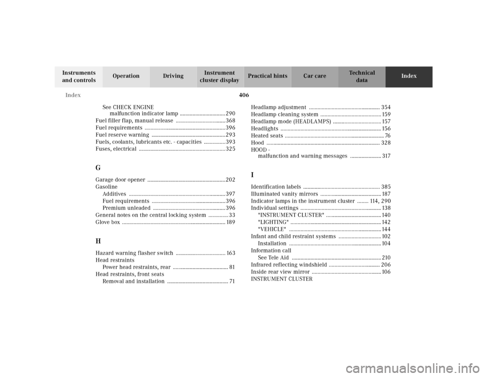
See CHECK ENGINE
malfunction indicator lamp ................................290
Fuel filler flap, manual release ...................................368
Fuel requirements .........................................................396
Fuel reserve warning ....................................................293
Fuels, coolants, lubricants etc. - capacities ...............393
Fuses, electrical .............................................................325
GGarage door opener .......................................................202
Gasoline
Additives ....................................................................397
Fuel requirements ....................................................396
Premium unleaded ...................................................396
General notes on the central locking system .............. 33
Glove box ......................................................................... 189HHazard warning flasher switch ................................... 163
Head restraints
Power head restraints, rear ....................................... 81
Head restraints, front seats
Removal and installation ........................................... 71Headlamp adjustment .................................................. 354
Headlamp cleaning system ........................................... 159
Headlamp mode (HEADLAMPS) .................................. 157
Headlights ....................................................................... 156
Heated seats ...................................................................... 76
Hood ................................................................................ 328
HOOD -
malfunction and warning messages ...................... 317
IIdentification labels ...................................................... 385
Illuminated vanity mirrors ........................................... 187
Indicator lamps in the instrument cluster ........ 114, 290
Individual settings ......................................................... 138
"INSTRUMENT CLUSTER" .......................................140
"LIGHTING" ................................................................ 142
"VEHICLE" .................................................................144
Infant and child restraint systems ..............................102
Installation .................................................................104
Information call
See Tele Aid ............................................................... 210
Infrared reflecting windshield .................................... 206
Inside rear view mirror .................................................106
INSTRUMENT CLUSTER