turn signal MERCEDES-BENZ CL600 2001 C215 User Guide
[x] Cancel search | Manufacturer: MERCEDES-BENZ, Model Year: 2001, Model line: CL600, Model: MERCEDES-BENZ CL600 2001 C215Pages: 424, PDF Size: 27.87 MB
Page 208 of 424
205 Garage door opener
Te ch n ica l
data Instruments
and controlsOperationDrivingInstrument
cluster displayPractical hints Car care Index Operation of remote control:
1. Turn electronic key in starter switch to position 1
or 2.
2. Select and press the appropriate button to activate
the remote controlled device. The integrated remote
control transmitter continues to send the signal as
long as the button is pressed – up to 20 seconds.Erasing the remote control memory:
1. Turn electronic key in starter switch to position 1
or 2.
2. Simultaneously holding down the left and right side
buttons for approximately 20 seconds, or until the
control lamp blinks rapidly, will erase the codes of
all three channels.
Page 220 of 424
215 Tele Aid
Te ch n ica l
data Instruments
and controlsOperationDrivingInstrument
cluster displayPractical hints Car care Index Notes:
The indicator lamp in the Roadside Assistance
button remains illuminated in red for approx.
10 seconds during the system self-check after turning
electronic key in starter switch to position 2 (together
with the “SOS” button and the Information
button¡).
See system self-check on page 210 when the indicator
lamp does not light up in red or stays on longer than
approximately 10 seconds.
If the indicator lamp in the Roadside Assistance
button is illuminated continuously and there was
no voic e connec tion to th e Response Cente r establ ish ed,
then the Tele Aid system could not initiate an Roadside
Assistance call (e.g. the relevant cellular phone network
is not available). The message “ROADSIDE
ASSISTANCE – CALL FAILED” appears in the
multifunction display.
Roadside Assistance calls can be terminated using the
ìbutton on the multifunction steering wheel.Information button ¡
Located below the center armrest cover is the
Information button¡. Pressing and holding the
button (for longer than 2 seconds) will initiate a call to
th e Cl ient Assistance Center. The bu tton will f la sh wh il e
the call is in progress. The message “INFO –
CONNECTING CALL” will appear in the multifunction
display. When the connection is established, the
message “INFO – CALL CONNECTED” appears in the
multifunction display. The Tele Aid system will transmit
data generating the vehicle identification number,
model, color and location (subject to availability of
cellular and GPS signals).
A voice connection between the Client Assistance
Center representative and the occupants of the vehicle
will be established. When a voice connection is
established the audio system mutes and the message
“TELE AID – INFO CALL ACTIVE” appears in the
multifunction display. Information regarding the
operation of your vehicle, the nearest Mercedes-Benz
Center or Mercedes-Benz USA products and services is
ava il ab l e to you .
For more details concerning Tele Aid, please visit
www.mbusa.com and use your ID and password, sent to
you separately, to learn more (USA only).
Page 221 of 424
216 Tele Aid
Te ch n ica l
data Instruments
and controlsOperationDrivingInstrument
cluster displayPractical hints Car care Index
Notes:
The indicator lamp in the Information button¡
remains illuminated in red for approx. 10 seconds
during the system self-check after turning electronic
key in starter switch to position 2 (together with the
“SOS” button and the Roadside Assistance button).
See system self-check on page 210 when the indicator
lamp does not light up in red or stays on longer than
approximately 10 seconds.
If the indicator lamp in the Information button¡ is
illuminated continuously and there was no voice
connection to the Response Center established, then the
Tele Aid system could not initiate an Information call
(e.g. the relevant cellular phone network is not
available). The message “info – CALL FAILED” appears
in the multifunction display.
Information calls can be terminated using the
ìbutton on the multifunction steering wheel.Important!
If the indicator lamps do not start f lashing after
pressing one of the buttons or remain illuminated (in
red ) at any time, th e Tele Aid system h as detected a fa ult
or the service is not currently active, and may not
initiate a call. Visit your Mercedes-Benz Center and
have the system ch ecked or conta ct t he Response Center
at 1-800-756-9018 (in the USA) or 1-888-923-8367 (in
Canada) as soon as possible.
Upgrade Signals
Tele Aid system processes calls using the following
priority.
•Automatic emergency – First priority
•Manual emergency – Second priority
•Roadside assistance – Third priority
•Information – Fourth priority
Should a higher priority call be initiated while you are
connected, an upgrade (alternating) tone will be heard,
and the appropriate indicator lamp will flash. If certain
information such as vehicle identification number or
client information is not available, the operator may
need to retransmit.
Page 233 of 424
228 Starting and turning off the engine
Te ch n ica l
data Instruments
and controlsOperationDrivingInstrument
cluster displayPractical hints Car care Index
Turning off
Turning off the engine with electronic key:
Put the selector lever in position “P” and turn the
electronic key in the starter switch to position 0 to stop
the engine.
The electronic key can only be removed with the
selector lever in position “P”.
Turning off the engine with KEYLESS-GO:
Stop the vehicle and put the selector lever in
position “P”.
Press start-/stop button on the selector lever until the
engine stops. With the driver’s door closed the starter
switch is set to the “On” position (starter switch
position 1). With the driver’s door opened the starter
switch is set to the “Off” position (starter switch
position 0, same as electronic key removed from starter
switch).Note:
The engine can only be turned off with selector lever in
position “P”. If attempting to turn off the engine while
the selector lever is in any other position than “P” a
signal sounds and the message “SELECTOR LEVER
TO P” appears in the multifunction display as a
reminder to move the selector to position “P”.
Page 263 of 424
258 Driving systems
Te ch n ica l
data Instruments
and controlsOperationDrivingInstrument
cluster displayPractical hints Car care Index
Deactivation of Distronic
Briefly move the distronic control lever in “OFF”
direction (3) – the stored speed remains in the memory
until the electronic key in the starter switch is turned to
position 1 or 0.
Distronic is also deactivated if:
•the service brake pedal is depressed,
•the parking brake is activated,
•the vehicle decelerates to less than approximately
25 mph (Canada: 30 km/h), e.g. while maintaining
the distance to the vehicle ahead.•the gear selector lever is moved to position “N”,
•the electronic stability program (ESP) is active,
•the electronic stability program (ESP) is switched off
manually,
•Model CL 55 AMG only:
the vehicle speed exceeds approximately 160 mph
(260 km/h).
Note:
A signal sounds and the message “DTR OFF” appears
for 5 seconds in the multifunction display everytime
Distronic is deactivated.
Wa r n i n g !
The Distronic switches off and releases the brakes
when the vehicle decelerates below the minimum
speed of 25 mph (Canada: 30 km/h) by operation of
the system. At that time, the driver must apply the
brakes in order to reduce vehicle speed further or
bring it to a stop.
Page 291 of 424
286 What you should know at the gas station
Te ch n ica l
data Instruments
and controlsOperationDrivingInstrument
cluster displayPractical hints Car care Index
Tire pressure
For tire pressure, refer to tire pressure label inside the
fuel filler flap. See page 345 for further details.
Air conditioner
R-134a refrigerant and special PAG lubricant, refer to
“Technical Data”.
Spark plugs
Approved spark plugs, refer to page 391.
Windshield cleaning
To prevent damage to the engine hood, the windshield
wipers must not be folded forward in parked position.
See page 380 for cleaning the windshield.Bulbs
Low beam: Xenon,
high beam: H7 (55 W)
fog lamps: H1 (55 W),
turn signal lamps, front: 1156 NA bulb,
parking and standing lamps, front: H 6W
side marker lamps, front: W 5 W/4 cp,
turn signal lamps, rear: 1156 NA bulb,
tail and parking lamp: 67/4 cp,
tail, parking and rear fog lamp, driver’s side: P 21/4 W,
tail, parking, standing and
side marker lamp: 67/4 cp,
backup lamps: 1160/32 cp,
license plate lamps: C 5 W/4 cp
Page 312 of 424
306 Malfunction and warning messages
Te ch n ica l
data Instruments
and controlsOperation DrivingInstrument
cluster displayPractical hints Car care Index
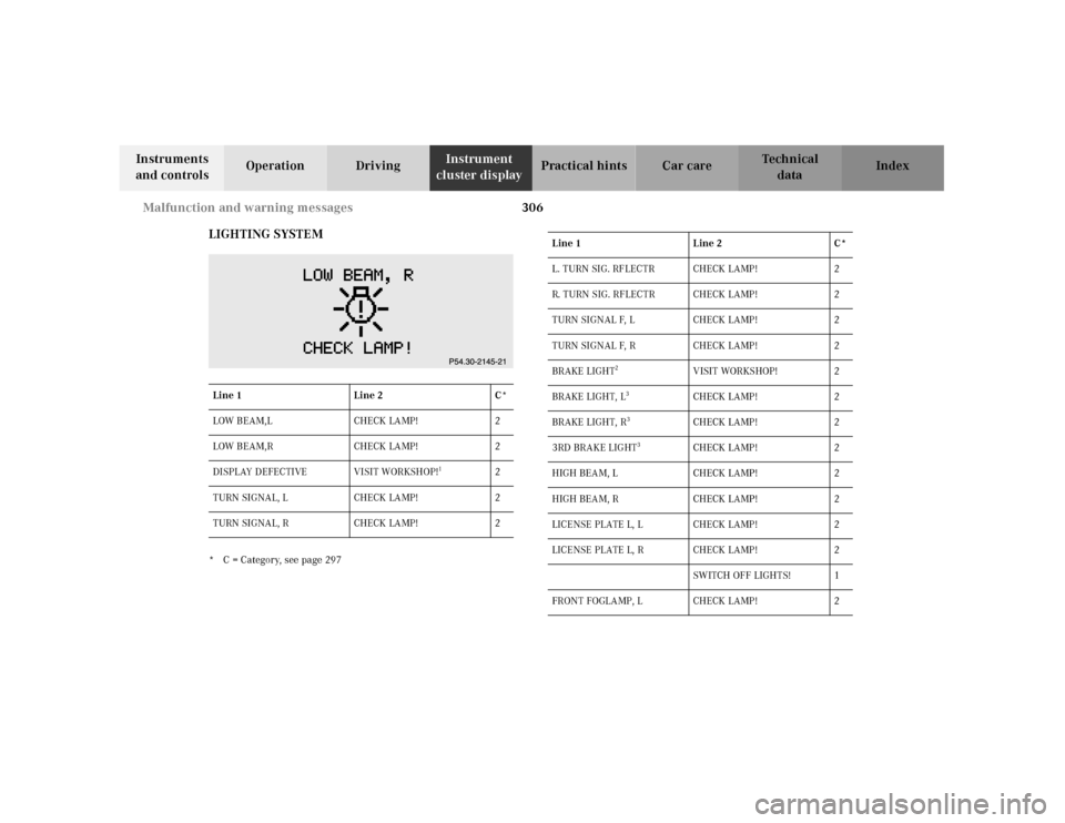
LIGHTING SYSTEM
* C = Category, see page 297Line 1 Line 2 C*
LOW BEAM,L CHECK LAMP! 2
LOW BEAM,R CHECK LAMP! 2
DISPLAY DEFECTIVE VISIT WORKSHOP!
1
2
TURN SIGNAL, L CHECK LAMP! 2
TURN SIGNAL, R CHECK LAMP! 2
Line 1 Line 2 C*
L. TURN SIG. RF LECTR CHECK LAMP! 2
R. TURN SIG. RFLECTR CHECK LAMP! 2
TURN SIGNAL F, L CHECK LAMP! 2
TURN SIGNAL F, R CHECK LAMP! 2
BRAKE LIGHT
2
VISIT WORKSHOP! 2
BRAKE LIGHT, L
3
CHECK LAMP ! 2
BRAKE LIGHT, R
3
CHECK LAMP ! 2
3RD BRAKE LIGHT
3
CHECK LAMP ! 2
HIGH BEAM, L CHECK LAMP! 2
HIGH BEAM, R CHECK LAMP! 2
LICENSE PLATE L, L CHECK LAMP! 2
LICENSE PLATE L, R CHECK LAMP! 2
SWITCH OFF LIGHTS! 1
FRONT FOGLAMP, L CHECK LAMP! 2
Page 359 of 424
353 Towing the vehicle
Te ch n ica l
data Instruments
and controlsOperation DrivingInstrument
cluster displayPractical hintsCar care Index We recommend that the vehicle be transported using
flat bed equipment. This method is preferable to other
types of towing.
Important!
To prevent damage du ri ng transport, do not ti e down
vehicle by its chassis or suspension parts.
The vehicle may be towed with all wheels on the ground
and the selector lever in position “N” for distances up to
30 miles (50 km) and at a speed not to exceed 30 mph
(50 km/h). The electronic key must be in starter switch
position 2.
To be certain to avoid a possibility of damage to the
transmission, however, we recommend the drive shaft
be disconnected at the rear axle drive f lange for any
towing beyond a short tow to a nearby garage.
Do not tow with sling-type equipment. Towing with
sling-type equipment over bumpy roads will damage
radiator and supports.
Use wheel lift, dolly, or flat bed equipment, with
electronic key in starter switch turned to position 0.Note:
To signal turns while being towed with hazard warning
flasher in use, turn electronic key in starter switch to
position 2 and activate combination switch for left or
right turn signal in usual manner – only the selected
turn signal will operate.
Upon canceling the turn signal, the hazard warning
f lasher will operate again.
Caution!
If the vehicle is towed with the front axle raised, the
engine must be shut off (electronic key in starter switch
position 0 or 1). Otherwise, the ESP will immediately be
engaged and will apply the rear wheel brakes.
Switch off the tow-away alarm (see “VEHICLE” under
“Individual settings” on page 144) as well as the ESP
(see page 273).
Wa r n i n g !
With the engine not running, there is no power
assistance for the braking and steering systems. In
this case, it is important to keep in mind that a
considerably higher degree of effort is necessary to
brake and steer the vehicle.
Page 361 of 424
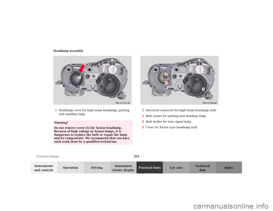
355 Exterior lamps
Te ch n ica l
data Instruments
and controlsOperation DrivingInstrument
cluster displayPractical hintsCar care Index Headlamp assembly
1Headlamp cover for high beam headlamp, parking
and standing lamp2 Electrical connector for high beam headlamp bulb
3Bulb socket for parking and standing lamp
4Bulb holder for turn signal lamp
5Cover for Xenon type headlamp bulb
Wa r n i n g !
Do not remove cover (5) for Xenon headlamp.
Because of high voltage in Xenon lamps, it is
dangerous to replace the bulb or repair the lamp
and its components. We recommend that you have
such work done by a qualified technician.
1
P82.10-2197-26
P82.10-2198-26
23
45
Page 363 of 424
![MERCEDES-BENZ CL600 2001 C215 User Guide 357 Exterior lamps
Te ch n ica l
data Instruments
and controlsOperation DrivingInstrument
cluster displayPractical hintsCar care Index Turn signal lamp
(1156 NA [26.9/5 W/32/4cp])
Open hood.
Twist b MERCEDES-BENZ CL600 2001 C215 User Guide 357 Exterior lamps
Te ch n ica l
data Instruments
and controlsOperation DrivingInstrument
cluster displayPractical hintsCar care Index Turn signal lamp
(1156 NA [26.9/5 W/32/4cp])
Open hood.
Twist b](/img/4/3348/w960_3348-362.png)
357 Exterior lamps
Te ch n ica l
data Instruments
and controlsOperation DrivingInstrument
cluster displayPractical hintsCar care Index Turn signal lamp
(1156 NA [26.9/5 W/32/4cp])
Open hood.
Twist bulb holder (4) counterclockwise and pull out.
Push bulb into socket, turn counterclockwise and
remove.
Insert new bulb in socket, push in and twist clockwise.
Reinstall bulb socket.
Align bulb holder (4) and turn clockwise to lock.Parking and standing lamp
H 6W
Open hood.
Press the clip together (arrow) and remove headlamp
cover (1).
Remove the bulb socket (3). Push bulb into socket, turn
counterclockwise and remove.
Insert new bulb in socket, push in and twist clockwise.
Reinstall bulb socket.
Align headlamp cover (1) and click into place.