buttons MERCEDES-BENZ CLA 2013 Owners Manual
[x] Cancel search | Manufacturer: MERCEDES-BENZ, Model Year: 2013, Model line: CLA, Model: MERCEDES-BENZ CLA 2013Pages: 352, PDF Size: 5.37 MB
Page 19 of 352
Steering (display message) .............. 253
Steering wheel Adjusting (manually) ......................100
Button overview ............................... 33
Buttons (on-board computer) ......... 209
Cleaning ......................................... 293
Gearshift paddles ........................... 156
Important safety notes ..................100
Steering wheel gearshift paddles .... 156
Stowage areas ................................... 268
Stowage compartment Spectacles compartment ...............269
Stowage compartments
Armrest (front) ............................... 269
Armrest (under) ............................. 270
Centre console .............................. 269
Centre console (rear) .....................270
Cup holder ..................................... 274
Glove compartment .......................269
Important safety information .........268
Luggage net ................................... 271
Under driver's seat/front-
passenger seat .............................. 270
Stowage well beneath the boot
floor .................................................... 273
Summer tyres .................................... 318
Sun visor ............................................ 275
Supplemental Restraint System see SRS (Supplemental Restraint
System)
Surround lighting (on-board com-
puter) .................................................. 222
Switching off the alarm (ATA) ............ 71
T
Tail lamps Display message ............................ 238
see Lights
Tank
see Fuel tank
Technical data
Capacities ...................................... 336
Emergency spare wheel .................332
Information .................................... 334
Trailer loads ................................... 345
Tyres/wheels ................................. 329
Vehicle data ................................... 343
Telephone
Accepting a call ............................. 216
Display message ............................ 254
Menu (on-board computer) ............215
Number from the phone book ........ 216
Redialling ....................................... 217
Rejecting/ending a call .................216
Telephone compartment ................270
Temperature
Coolant .......................................... 208
Outside temperature ...................... 209
Setting (climate control) ................130
TEMPOMAT
Function/notes ............................. 168
Theft-deterrent system
ATA (Anti-Theft Alarm system) .........71
Immobiliser ...................................... 71
Through-loading ................................ 271
Through-loading feature ................... 271
Time see Separate Owner's manual
TIREFIT kit .......................................... 299
Top Tether ............................................ 55
Tow-away protection .......................... 71
Towing Important safety notes ..................308
Towing a trailer
Active Parking Assist .....................191
Axle load, permissible ....................345
Bulb failure indicator for LED lamps 206
ESP ®
(Electronic Stability Program) . 70
Pulling away with a trailer ..............147
Trailer tow hitch display message ..253
Towing away
Fitting the towing eye ....................310
Removing the towing eye ...............310
With both axles on the ground .......310
With front axle raised ..................... 310
Tow-starting
Emergency engine starting ............311
Fitting the towing eye ....................310
Important safety notes ..................308
Removing the towing eye ...............310
Traction control ................................... 68
Trailer coupling see Towing a trailer Index17
Page 79 of 352
opened from the inside. Switch off the alarm
( Y page 71).
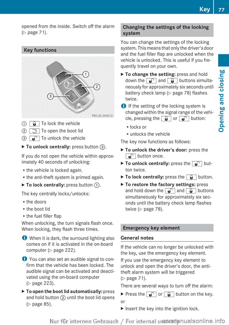
Key functions
:& To lock the vehicle;F To open the boot lid=% To unlock the vehicleXTo unlock centrally: press button =.
If you do not open the vehicle within approx-
imately 40 seconds of unlocking:
R the vehicle is locked again.
R the anti-theft system is primed again.
XTo lock centrally: press button :.
The key centrally locks/unlocks:
R the doors
R the boot lid
R the fuel filler flap
When unlocking, the turn signals flash once.
When locking, they flash three times.
i When it is dark, the surround lighting also
comes on if it is activated in the on-board
computer ( Y page 222).
i You can also set an audible signal to con-
firm that the vehicle has been locked. The
audible signal can be activated and deacti-
vated using the on-board computer
( Y page 223).
XTo open the boot lid automatically: press
and hold button ; until the boot lid opens
( Y page 85).Changing the settings of the locking
system
You can change the settings of the locking
system. This means that only the driver's door
and the fuel filler flap are unlocked when the
vehicle is unlocked. This is useful if you fre-
quently travel on your own.XTo change the setting: press and hold
down the % and & buttons simulta-
neously for approximately six seconds until
battery check lamp ( Y page 78) flashes
twice.
i If the setting of the locking system is
changed within the signal range of the vehi-
cle, pressing the & or % button:
R locks or
R unlocks the vehicle
The key now functions as follows:
XTo unlock the driver's door: press the
% button once.XTo unlock centrally: press the % but-
ton twice.XTo lock centrally: press the & button.XTo restore the factory settings: press
and hold down the % and & buttons
simultaneously for approximately six sec-
onds until the battery check lamp flashes
twice ( Y page 78).
Emergency key element
General notes
If the vehicle can no longer be unlocked with
the key, use the emergency key element.
If you use the emergency key element to
unlock and open the driver's door, the anti-
theft alarm system will be triggered
( Y page 71).
There are several ways to turn off the alarm:
XPress the % or & button on the key.
or
XInsert the key into the ignition lock.Key77Opening and closingZ
Page 81 of 352
Replacing the battery
You require a CR 2025 3 V cell battery.
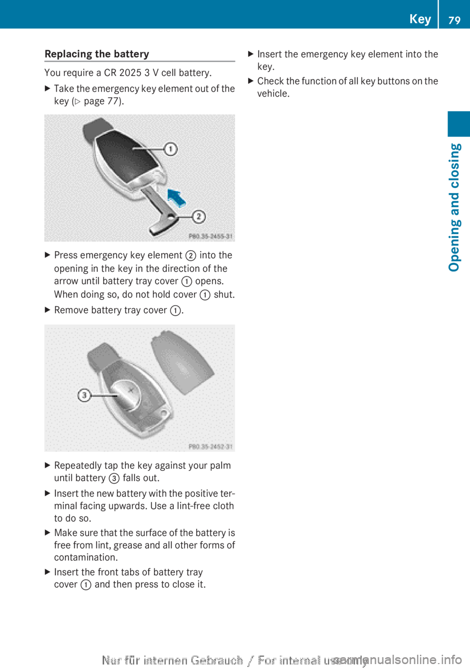
XTake the emergency key element out of the
key ( Y page 77).XPress emergency key element ; into the
opening in the key in the direction of the
arrow until battery tray cover : opens.
When doing so, do not hold cover : shut.XRemove battery tray cover :.XRepeatedly tap the key against your palm
until battery = falls out.XInsert the new battery with the positive ter-
minal facing upwards. Use a lint-free cloth
to do so.XMake sure that the surface of the battery is
free from lint, grease and all other forms of
contamination.XInsert the front tabs of battery tray
cover : and then press to close it.XInsert the emergency key element into the
key.XCheck the function of all key buttons on the
vehicle.Key79Opening and closingZ
Page 85 of 352
For all countries except the United King-
dom:
You can open a door from inside the vehicle
even if it has been locked.
If the vehicle has previously been locked with
the key, opening a door from the inside will
trigger the anti-theft alarm system. Switch off
the alarm ( Y page 71).
You can only open the rear doors from inside
the vehicle if they are not secured by the
child-proof locks ( Y page 63).
If the vehicle has been locked using the lock-
ing button for the central locking, or has been
locked automatically, and a door is opened
from the inside:
R the vehicle will be fully unlocked if it had
previously been fully unlocked
R only the door which has been opened form
the inside is unlocked if only the driver's
door had been previously unlocked
Only for the United Kingdom: if the vehicle
has been locked with the key, the double lock
function is activated as standard. It is then
not possible to open the doors from inside the
vehicle. You can deactivate the double lock
function by deactivating the interior motion
sensor ( Y page 72). The doors can then be
opened from the inside after the vehicle has
been locked from the outside. You can open
the rear doors from inside the vehicle if they
are not secured by the child-proof locks
( Y page 63). The anti-theft alarm system is
triggered if the door is opened from the
inside. Switch off the alarm ( Y page 71).
If the vehicle has been locked using the lock-
ing button for the central locking, or has been
locked automatically, and a door is opened
from the inside:
R the vehicle will be fully unlocked if it had
previously been fully unlocked
R only the door which has been opened form
the inside is unlocked if only the driver's
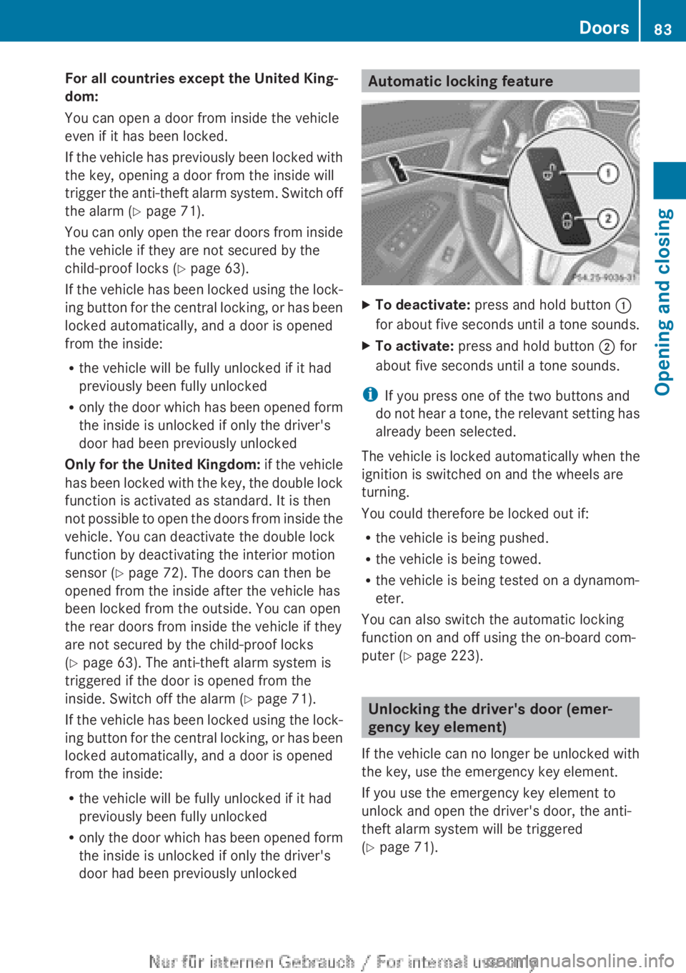
door had been previously unlockedAutomatic locking featureXTo deactivate: press and hold button :
for about five seconds until a tone sounds.XTo activate: press and hold button ; for
about five seconds until a tone sounds.
i If you press one of the two buttons and
do not hear a tone, the relevant setting has
already been selected.
The vehicle is locked automatically when the
ignition is switched on and the wheels are
turning.
You could therefore be locked out if:
R the vehicle is being pushed.
R the vehicle is being towed.
R the vehicle is being tested on a dynamom-
eter.
You can also switch the automatic locking
function on and off using the on-board com-
puter ( Y page 223).
Unlocking the driver's door (emer-
gency key element)
If the vehicle can no longer be unlocked with
the key, use the emergency key element.
If you use the emergency key element to
unlock and open the driver's door, the anti-
theft alarm system will be triggered
( Y page 71).
Doors83Opening and closingZ
Page 97 of 352
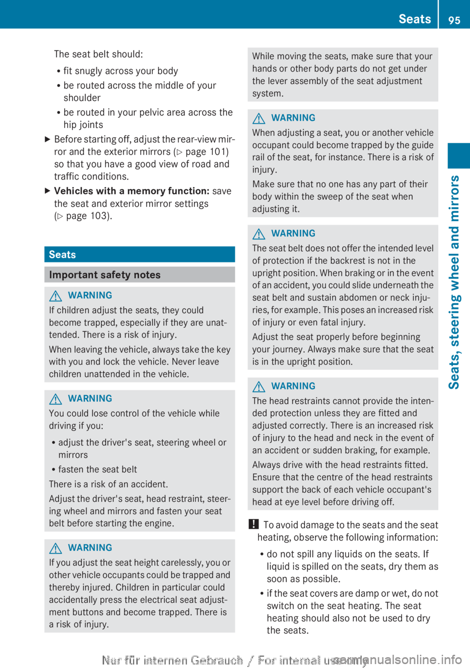
The seat belt should:
R fit snugly across your body
R be routed across the middle of your
shoulder
R be routed in your pelvic area across the
hip jointsXBefore starting off, adjust the rear-view mir-
ror and the exterior mirrors ( Y page 101)
so that you have a good view of road and
traffic conditions.XVehicles with a memory function: save
the seat and exterior mirror settings
( Y page 103).
Seats
Important safety notes
GWARNING
If children adjust the seats, they could
become trapped, especially if they are unat-
tended. There is a risk of injury.
When leaving the vehicle, always take the key
with you and lock the vehicle. Never leave
children unattended in the vehicle.
GWARNING
You could lose control of the vehicle while
driving if you:
R adjust the driver's seat, steering wheel or
mirrors
R fasten the seat belt
There is a risk of an accident.
Adjust the driver's seat, head restraint, steer-
ing wheel and mirrors and fasten your seat
belt before starting the engine.
GWARNING
If you adjust the seat height carelessly, you or
other vehicle occupants could be trapped and
thereby injured. Children in particular could
accidentally press the electrical seat adjust-
ment buttons and become trapped. There is
a risk of injury.
While moving the seats, make sure that your
hands or other body parts do not get under
the lever assembly of the seat adjustment
system.GWARNING
When adjusting a seat, you or another vehicle
occupant could become trapped by the guide
rail of the seat, for instance. There is a risk of
injury.
Make sure that no one has any part of their
body within the sweep of the seat when
adjusting it.
GWARNING
The seat belt does not offer the intended level
of protection if the backrest is not in the
upright position. When braking or in the event
of an accident, you could slide underneath the
seat belt and sustain abdomen or neck inju-
ries, for example. This poses an increased risk
of injury or even fatal injury.
Adjust the seat properly before beginning
your journey. Always make sure that the seat
is in the upright position.
GWARNING
The head restraints cannot provide the inten-
ded protection unless they are fitted and
adjusted correctly. There is an increased risk
of injury to the head and neck in the event of
an accident or sudden braking, for example.
Always drive with the head restraints fitted.
Ensure that the centre of the head restraints
support the back of each vehicle occupant's
head at eye level before driving off.
! To avoid damage to the seats and the seat
heating, observe the following information:
R do not spill any liquids on the seats. If
liquid is spilled on the seats, dry them as
soon as possible.
R if the seat covers are damp or wet, do not
switch on the seat heating. The seat
heating should also not be used to dry
the seats.
Seats95Seats, steering wheel and mirrorsZ
Page 129 of 352
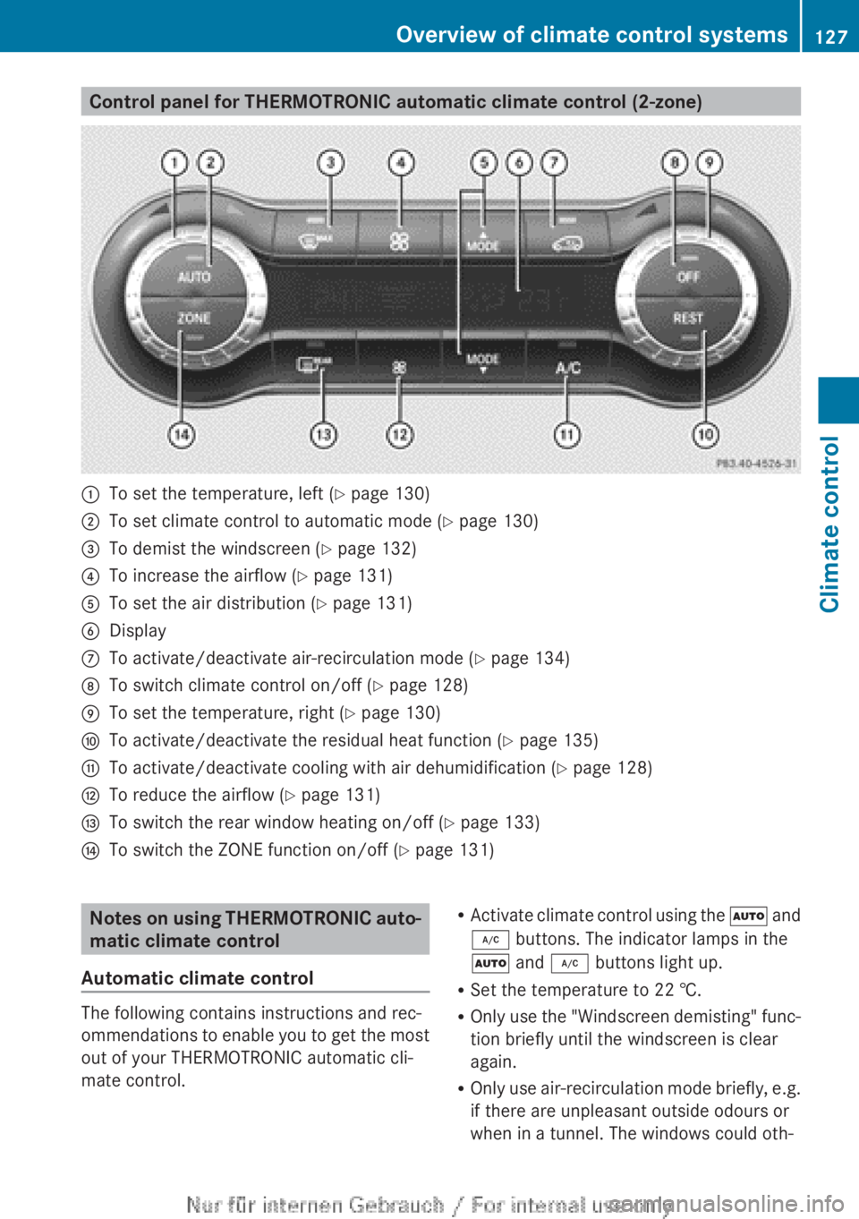
Control panel for THERMOTRONIC automatic climate control (2-zone):To set the temperature, left (Y page 130);To set climate control to automatic mode ( Y page 130)=To demist the windscreen ( Y page 132)?To increase the airflow ( Y page 131)ATo set the air distribution ( Y page 131)BDisplayCTo activate/deactivate air-recirculation mode ( Y page 134)DTo switch climate control on/off ( Y page 128)ETo set the temperature, right ( Y page 130)FTo activate/deactivate the residual heat function ( Y page 135)GTo activate/deactivate cooling with air dehumidification ( Y page 128)HTo reduce the airflow ( Y page 131)ITo switch the rear window heating on/off ( Y page 133)JTo switch the ZONE function on/off ( Y page 131)Notes on using THERMOTRONIC auto-
matic climate control
Automatic climate control
The following contains instructions and rec-
ommendations to enable you to get the most
out of your THERMOTRONIC automatic cli-
mate control.
R Activate climate control using the à and
¿ buttons. The indicator lamps in the
à and ¿ buttons light up.
R Set the temperature to 22 †.
R Only use the "Windscreen demisting" func-
tion briefly until the windscreen is clear
again.
R Only use air-recirculation mode briefly, e.g.
if there are unpleasant outside odours or
when in a tunnel. The windows could oth-Overview of climate control systems127Climate control
Page 133 of 352
Setting the air distribution
THERMATIC automatic climate control
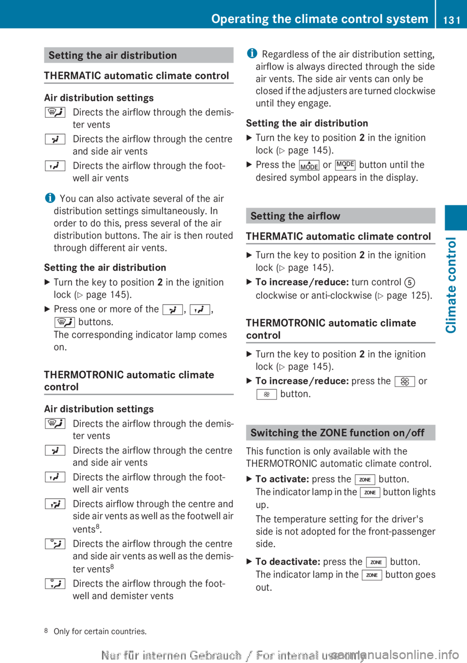
Air distribution settings
¯Directs the airflow through the demis-
ter ventsPDirects the airflow through the centre
and side air ventsODirects the airflow through the foot-
well air vents
i You can also activate several of the air
distribution settings simultaneously. In
order to do this, press several of the air
distribution buttons. The air is then routed
through different air vents.
Setting the air distribution
XTurn the key to position 2 in the ignition
lock ( Y page 145).XPress one or more of the P, O ,
¯ buttons.
The corresponding indicator lamp comes
on.
THERMOTRONIC automatic climate
control
Air distribution settings
¯Directs the airflow through the demis-
ter ventsPDirects the airflow through the centre
and side air ventsODirects the airflow through the foot-
well air ventsSDirects airflow through the centre and
side air vents as well as the footwell air
vents 8
.bDirects the airflow through the centre
and side air vents as well as the demis-
ter vents 8aDirects the airflow through the foot-
well and demister ventsi Regardless of the air distribution setting,
airflow is always directed through the side
air vents. The side air vents can only be
closed if the adjusters are turned clockwise
until they engage.
Setting the air distributionXTurn the key to position 2 in the ignition
lock ( Y page 145).XPress the É or Ë button until the
desired symbol appears in the display.
Setting the airflow
THERMATIC automatic climate control
XTurn the key to position 2 in the ignition
lock ( Y page 145).XTo increase/reduce: turn control A
clockwise or anti-clockwise ( Y page 125).
THERMOTRONIC automatic climate
control
XTurn the key to position 2 in the ignition
lock ( Y page 145).XTo increase/reduce: press the K or
I button.
Switching the ZONE function on/off
This function is only available with the
THERMOTRONIC automatic climate control.
XTo activate: press the á button.
The indicator lamp in the á button lights
up.
The temperature setting for the driver's
side is not adopted for the front-passenger
side.XTo deactivate: press the á button.
The indicator lamp in the á button goes
out.8 Only for certain countries.Operating the climate control system131Climate control
Page 140 of 352
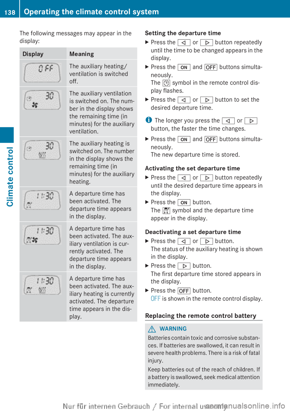
The following messages may appear in the
display:DisplayMeaningThe auxiliary heating/
ventilation is switched
off.The auxiliary ventilation
is switched on. The num-
ber in the display shows
the remaining time (in
minutes) for the auxiliary
ventilation.The auxiliary heating is
switched on. The number
in the display shows the
remaining time (in
minutes) for the auxiliary
heating.A departure time has
been activated. The
departure time appears
in the display.A departure time has
been activated. The aux-
iliary ventilation is cur-
rently activated. The
departure time appears
in the display.A departure time has
been activated. The aux-
iliary heating is currently
activated. The departure
time appears in the dis-
play.Setting the departure timeXPress the , or . button repeatedly
until the time to be changed appears in the
display.XPress the u and ^ buttons simulta-
neously.
The Î symbol in the remote control dis-
play flashes.XPress the , or . button to set the
desired departure time.
i The longer you press the , or .
button, the faster the time changes.
XPress the u and ^ buttons simulta-
neously.
The new departure time is stored.
Activating the set departure time
XPress the , or . button repeatedly
until the desired departure time appears in
the display.XPress the u button.
The Í symbol and the departure time
appear in the display.
Deactivating a set departure time
XPress the , or . button.
The status of the auxiliary heating is shown
in the display.XPress the . button.
The first departure time stored appears in
the display.XPress the ^ button.
OFF is shown in the remote control display.
Replacing the remote control battery
GWARNING
Batteries contain toxic and corrosive substan-
ces. If batteries are swallowed, it can result in
severe health problems. There is a risk of fatal
injury.
Keep batteries out of the reach of children. If
a battery is swallowed, seek medical attention
immediately.
138Operating the climate control systemClimate control
Page 211 of 352
At high outside temperatures and when driv-
ing uphill, the coolant temperature may rise
to the end of the scale.
Rev counter
! Do not drive in the overrevving range.
Doing so will damage the engine.
The red band in the rev counter indicates the
engine's overrevving range.
The fuel supply is interrupted to protect the
engine when the red band is reached.
Outside temperature display
You should pay special attention to road con-
ditions when temperatures are around the
freezing point.
The outside temperature display is in the mul-
tifunction display.
Changes in the outside temperature are dis-
played after a short delay.
Speedometer with segments
The speedometer is divided into segments on
vehicles with DISTRONIC PLUS.
The segments in the speedometer indicate
which speed range is available.
R Cruise control activated ( Y page 168):
The segments light up from the stored
speed to the maximum speed.
R Variable SPEEDTRONIC activated
( Y page 171):
The segments light up from the start of the
scale to the selected limit speed.
R DISTRONIC PLUS activated ( Y page 173):
One or two segments in the set speed
range light up.
R DISTRONIC PLUS detects a vehicle in front:
The segments between the speed of the
vehicle in front and the stored speed light
up.
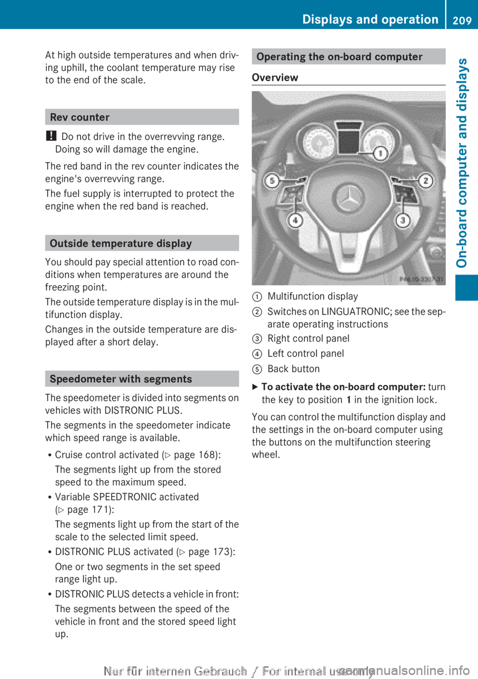
Operating the on-board computer
Overview:Multifunction display;Switches on LINGUATRONIC; see the sep-
arate operating instructions=Right control panel?Left control panelABack buttonXTo activate the on-board computer: turn
the key to position 1 in the ignition lock.
You can control the multifunction display and
the settings in the on-board computer using
the buttons on the multifunction steering
wheel.
Displays and operation209On-board computer and displaysZ
Page 281 of 352
Using a mobile phone
If the mobile phone is inserted in the mobile
phone bracket, you can speak to the person
you are calling using the hands-free system.
XOpen the telephone compartment
( Y page 270).XPlace the mobile phone bracket into the
pre-installed fitting (see the separate
installation instructions for the mobile
phone fitting).XInsert the mobile phone into the mobile
phone bracket (see the separate installa-
tion instructions for the mobile phone fit-
ting).
i On some mobile phone brackets, first you
have to connect the phone to the mobile
phone bracket via Bluetooth ®
(see the sep-
arate operating instructions for the mobile
phone bracket).
If this is the case, the mobile phone does
not have to be inserted into the bracket for
you to be able to use the telephone func-
tions. However, the charging function and
aerial function are not available.
Operating the mobile phone
You can operate the telephone using the
6 and ~ buttons on the multifunction
steering wheel. You can operate other mobile
phone functions via the on-board computer
( Y page 215).
When you remove the key from the ignition
lock, the mobile phone stays switched on.
However, you can no longer use the hands-
free system.
If you have an active call and would like to
take the key out of the ignition lock, first
remove the mobile phone from the bracket.
i If you use a mobile phone bracket which
is connected to your mobile via Blue-
tooth ®
and you wish to continue a call on
your mobile phone:
You should switch the call to "Private
mode" before you remove the key from the
ignition lock. Otherwise, it will take up to
20 seconds for the mobile phone to dis-
connect from the system. Only then can
you continue the call on your mobile phone.
Notes on the necessary steps for setting
"Private mode" can be found in the sepa-
rate operating instructions of the mobile
phone.
i Not all mobile phones support "Private
mode".
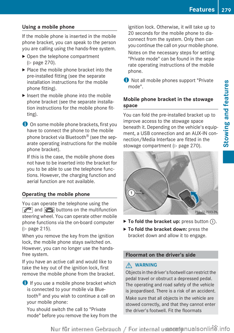
Mobile phone bracket in the stowage
space
You can fold the pre-installed bracket up to
improve access to the stowage space
beneath it. Depending on the vehicle's equip-
ment, a USB connection and an AUX-IN con-
nection/Media Interface are fitted in the
stowage compartment ( Y page 270).
XTo fold the bracket up: press button :.XTo fold the bracket down: press the
bracket down and allow it to engage.
Floormat on the driver's side
GWARNING
Objects in the driver's footwell can restrict the
pedal travel or obstruct a depressed pedal.
The operating and road safety of the vehicle
is jeopardised. There is a risk of an accident.
Make sure that all objects in the vehicle are
stowed correctly, and that they cannot enter
the driver's footwell. Fit the floormats
Features279Stowing and featuresZ