seats MERCEDES-BENZ CLA-Class 2014 C117 Owner's Guide
[x] Cancel search | Manufacturer: MERCEDES-BENZ, Model Year: 2014, Model line: CLA-Class, Model: MERCEDES-BENZ CLA-Class 2014 C117Pages: 358, PDF Size: 6.6 MB
Page 102 of 358
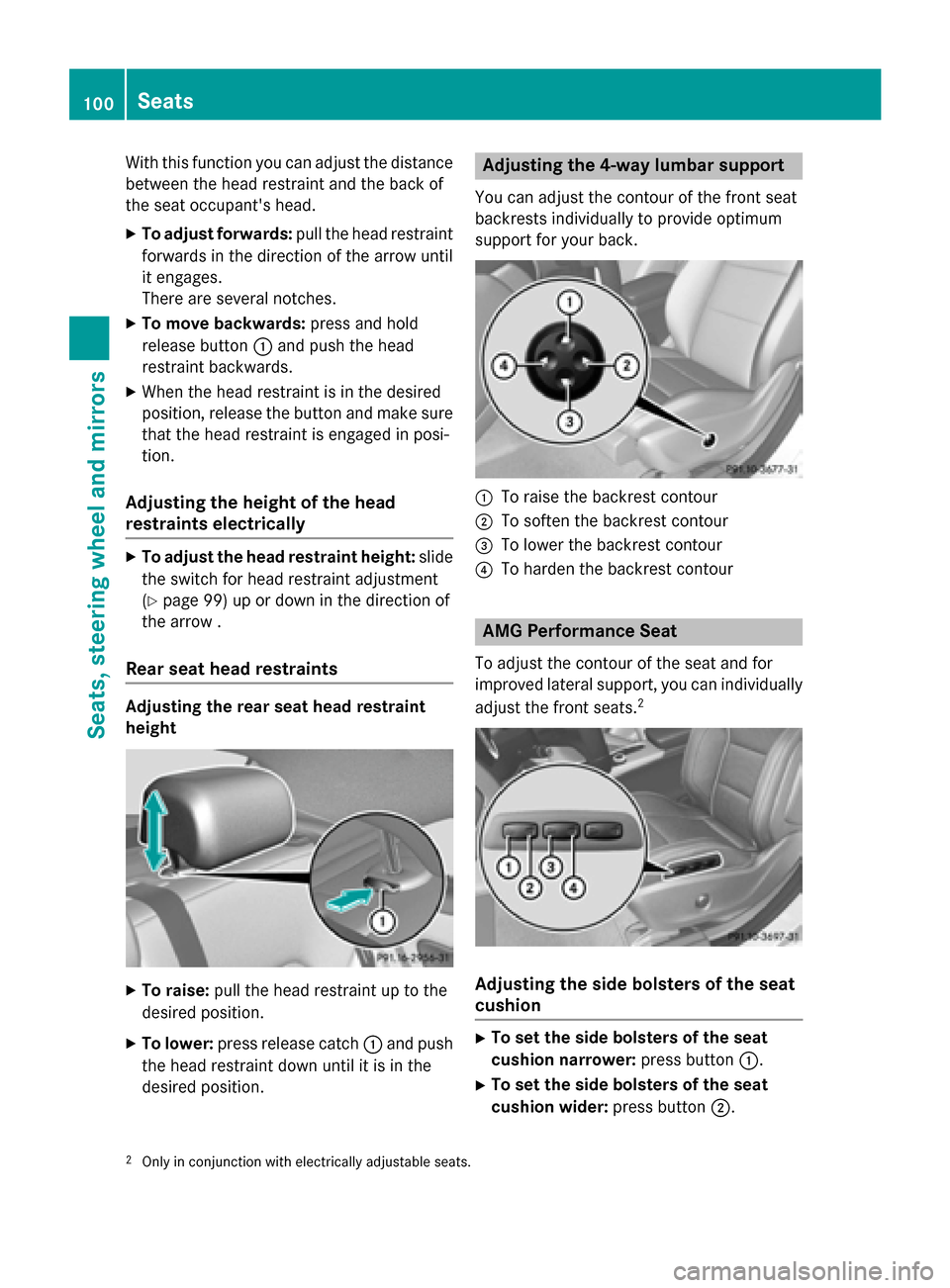
With this function you can adjust the distance
between the head restraint and the back of
the seat occupant's head.
X To adjust forwards: pull the head restraint
forwards in the direction of the arrow until
it engages.
There are several notches.
X To move backwards: press and hold
release button 0043and push the head
restraint backwards.
X When the head restraint is in the desired
position, release the button and make sure
that the head restraint is engaged in posi-
tion.
Adjusting the height of the head
restraints electrically X
To adjust the head restraint height: slide
the switch for head restraint adjustment
(Y page 99) up or down in the direction of
the arrow .
Rear seat head restraints Adjusting the rear seat head restraint
height X
To raise: pull the head restraint up to the
desired position.
X To lower: press release catch 0043and push
the head restraint down until it is in the
desired position. Adjusting the 4-way lumbar support
You can adjust the contour of the front seat
backrests individually to provide optimum
support for your back. 0043
To raise the backrest contour
0044 To soften the backrest contour
0087 To lower the backrest contour
0085 To harden the backrest contour AMG Performance Seat
To adjust the contour of the seat and for
improved lateral support, you can individually adjust the front seats. 2 Adjusting the side bolsters of the seat
cushion
X
To set the side bolsters of the seat
cushion narrower: press button0043.
X To set the side bolsters of the seat
cushion wider: press button0044.
2 Only in conjunction with electrically adjustable seats. 100
SeatsSeats, steering wheel and mirrors
Page 103 of 358
Adjusting the seat backrest side bol-
sters
X
To set the side bolsters of the seat
backrest narrower: press button0087.
X To set the side bolsters of the seat
backrest wider: press button0085. Switching the seat heating on/off
Activating/deactivating G
WARNING
Repeatedly switching on the seat heating can
cause the seat cushion and backrest pads to
become very hot. The health of persons with
limited temperature sensitivity or a limited
ability to react to excessively high tempera-
tures may be affected or they may even suffer burn-like injuries. There is a risk of injury.
Therefore, do not switch the seat heating on
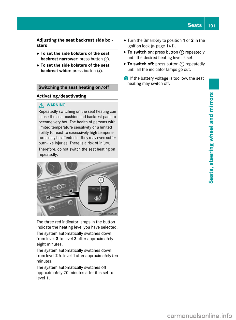
repeatedly. The three red indicator lamps in the button
indicate the heating level you have selected.
The system automatically switches down
from level 3to level 2after approximately
eight minutes.
The system automatically switches down
from level 2to level 1after approximately ten
minutes.
The system automatically switches off
approximately 20 minutes after it is set to
level 1. X
Turn the SmartKey to position 1or 2in the
ignition lock (Y page 141).
X To switch on: press button0043repeatedly
until the desired heating level is set.
X To switch off: press button0043repeatedly
until all the indicator lamps go out.
i If the battery voltage is too low, the seat
heating may switch off. Seats
101Seats, steering wheel and mirrors Z
Page 104 of 358
Problems with the seat heating
Problem
Possible causes/consequences and
0050
0050Solutions The seat heating has
switched off prema-
turely or cannot be
switched on. The on-board voltage is too low because too many electrical con-
sumers are switched on.
X Switch off electrical consumers that you do not need, such as
the rear window defroster or interior lighting.
Once the battery is sufficiently charged, the seat heating will
switch back on automatically. Steering wheel
Important safety notes
G
WARNING
You could lose control of your vehicle if you do the following while driving:
R adjust the driver's seat, head restraint,
steering wheel or mirrors
R fasten the seat belt
There is a risk of an accident.
Adjust the driver's seat, head restraint, steer-
ing wheel and mirror and fasten your seat belt before starting the engine. G
WARNING
Children could injure themselves if they
adjust the steering wheel. There is a risk of
injury.
When leaving the vehicle, always take the
SmartKey with you and lock the vehicle. Never leave children unsupervised in the vehicle. Adjusting the steering wheel
G
WARNING
If the steering wheel is unlocked while the
vehicle is in motion, it could change position
unexpectedly. This could cause you to lose
control of the vehicle. There is a risk of an
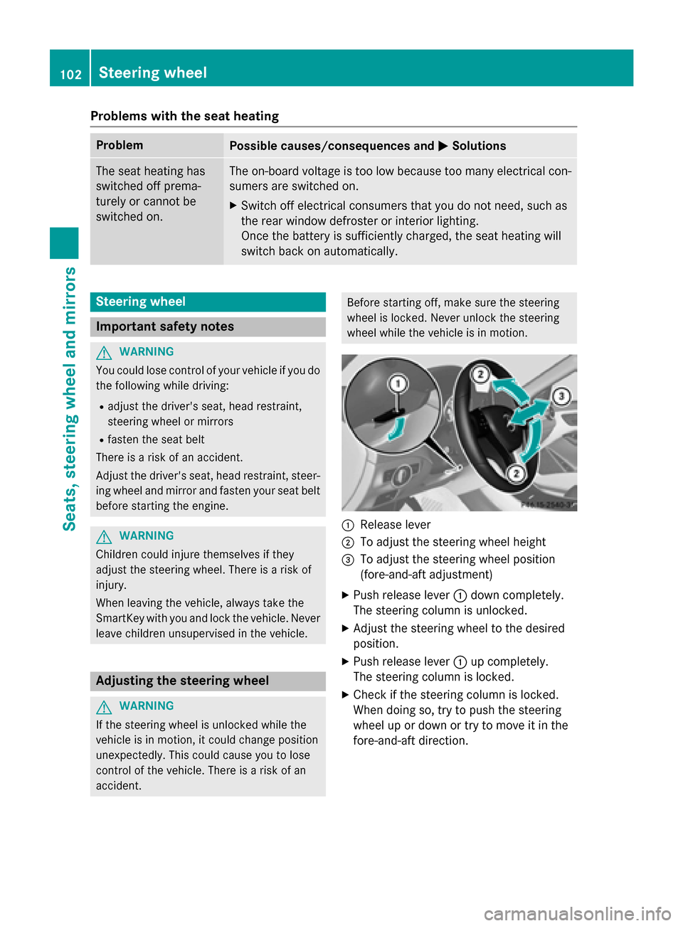
accident. Before starting off, make sure the steering
wheel is locked. Never unlock the steering
wheel while the vehicle is in motion. 0043
Release lever
0044 To adjust the steering wheel height
0087 To adjust the steering wheel position
(fore-and-aft adjustment)
X Push release lever 0043down completely.
The steering column is unlocked.
X Adjust the steering wheel to the desired
position.
X Push release lever 0043up completely.
The steering column is locked.
X Check if the steering column is locked.
When doing so, try to push the steering
wheel up or down or try to move it in the
fore-and-aft direction. 102
Steering wheelSeats, steering wheel and mirrors
Page 105 of 358
Mirrors
Rear-view mirror
X
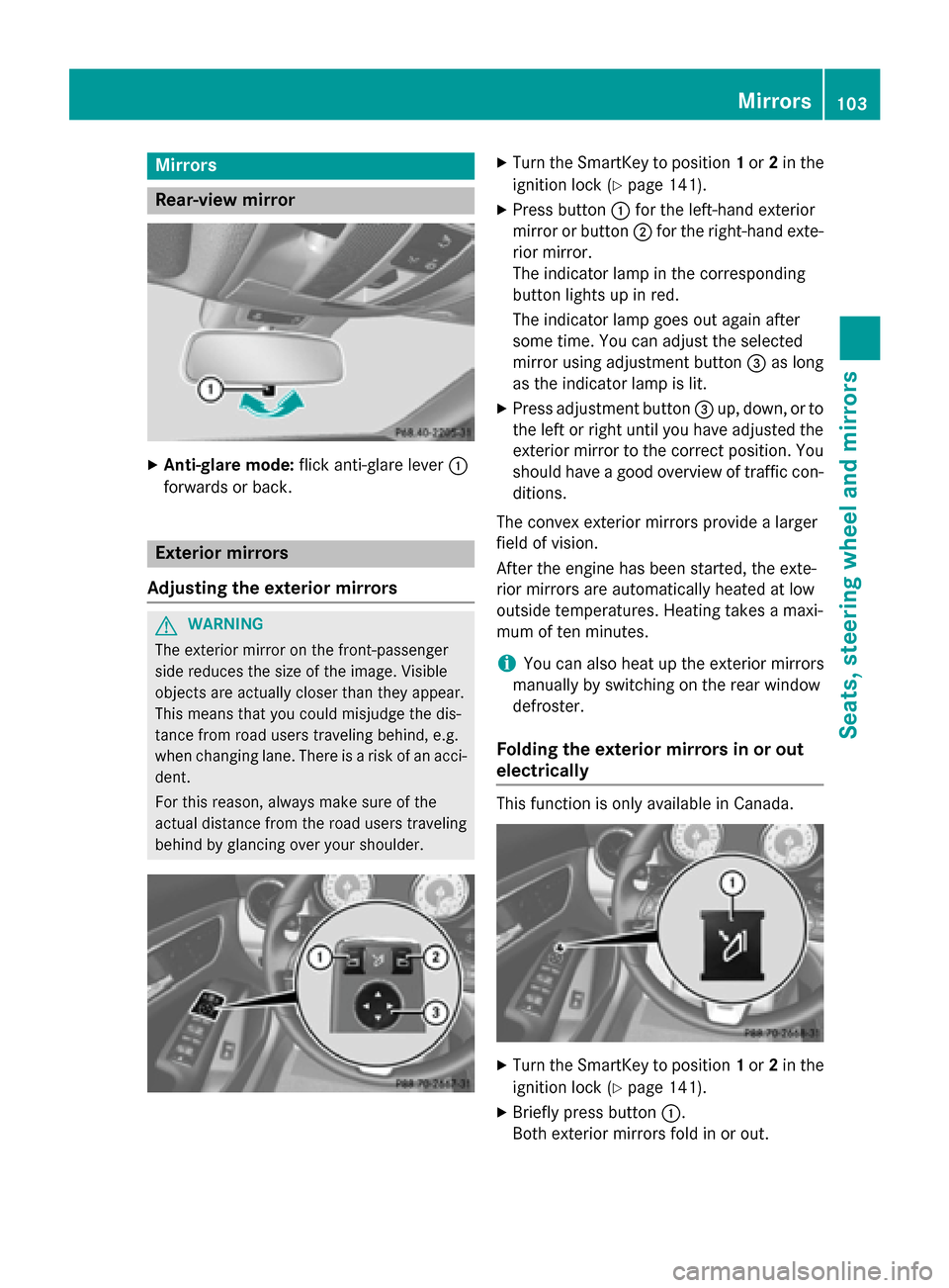
Anti-glare mode: flick anti-glare lever 0043
forwards or back. Exterior mirrors
Adjusting the exterior mirrors G
WARNING
The exterior mirror on the front-passenger
side reduces the size of the image. Visible
objects are actually closer than they appear.
This means that you could misjudge the dis-
tance from road users traveling behind, e.g.
when changing lane. There is a risk of an acci-
dent.
For this reason, always make sure of the
actual distance from the road users traveling
behind by glancing over your shoulder. X
Turn the SmartKey to position 1or 2in the
ignition lock (Y page 141).
X Press button 0043for the left-hand exterior
mirror or button 0044for the right-hand exte-
rior mirror.
The indicator lamp in the corresponding
button lights up in red.
The indicator lamp goes out again after
some time. You can adjust the selected
mirror using adjustment button 0087as long
as the indicator lamp is lit.
X Press adjustment button 0087up, down, or to
the left or right until you have adjusted the
exterior mirror to the correct position. You
should have a good overview of traffic con- ditions.
The convex exterior mirrors provide a larger
field of vision.
After the engine has been started, the exte-
rior mirrors are automatically heated at low
outside temperatures. Heating takes a maxi-
mum of ten minutes.
i You can also heat up the exterior mirrors
manually by switching on the rear window
defroster.
Folding the exterior mirrors in or out
electrically This function is only available in Canada.
X
Turn the SmartKey to position 1or 2in the
ignition lock (Y page 141).
X Briefly press button 0043.
Both exterior mirrors fold in or out. Mirrors
103Seats, steering wheel and mirrors Z
Page 106 of 358

i
Make sure that the exterior mirrors are
always folded out fully while driving. They
could otherwise vibrate.
i If you are driving faster than 30 mph
(47 km/h), you can no longer fold in the
exterior mirrors.
Setting the exterior mirrors This function is only available in Canada.
If the battery has been disconnected or com-
pletely discharged, the exterior mirrors must
be reset. The exterior mirrors will otherwise
not fold in when you select the "Fold in mir-
rors when locking" function in the on-board
computer (Y page 210).
X Turn the SmartKey to position 1in the igni-
tion lock (Y page 141).
X Briefly press button 0043.
Folding the exterior mirrors in or out
automatically This function is only available in Canada.
If the "Fold in mirrors when locking" function
is activated in the on-board computer
(Y page 210):
R the exterior mirrors fold in automatically as
soon as you lock the vehicle from the out-
side.
R the exterior mirrors fold out again automat-
ically as soon as you unlock the vehicle and
then open the driver's or front-passenger
door.
i If the exterior mirrors have been folded in
manually, they do not fold out.
Exterior mirror pushed out of position If an exterior mirror has been pushed out of
position, proceed as follows:
X Vehicles without electrically folding
exterior mirrors: move the exterior mirror
into the correct position manually.
X Vehicles with electrically folding exte-
rior mirrors: press and hold mirror-folding button (Y
page 103) until you hear a click
and then the mirrors engage in position.
The mirror housing is engaged again and
you can adjust the exterior mirrors as usual
(Y page 103). Automatic anti-glare mirrors
The "Automatic anti-glare mirrors" function is
only available if the vehicle is equipped with
the "Mirrors package".
The rear-view mirror and the exterior mirror
on the driver's side automatically go into anti- glare mode if:
R the ignition is switched on and
R incident light from headlamps strikes the
sensor in the rear-view mirror.
The mirrors do not go into anti-glare mode if
reverse gear is engaged or the interior lighting is switched on. Parking position for the exterior mir-
ror on the front-passenger side
General notes The "Parking position of the exterior mirror on
the front-passenger side" function is only
available if the vehicle is equipped with the
"Mirrors package".
Setting and storing the parking position Using reverse gear
You can position the front-passenger side
exterior mirror in such a way that you can see
the rear wheel on that side as soon as you
engage reverse gear. You can store this posi-
tion. 104
MirrorsSeats, steering wheel and mirrors
Page 107 of 358
X
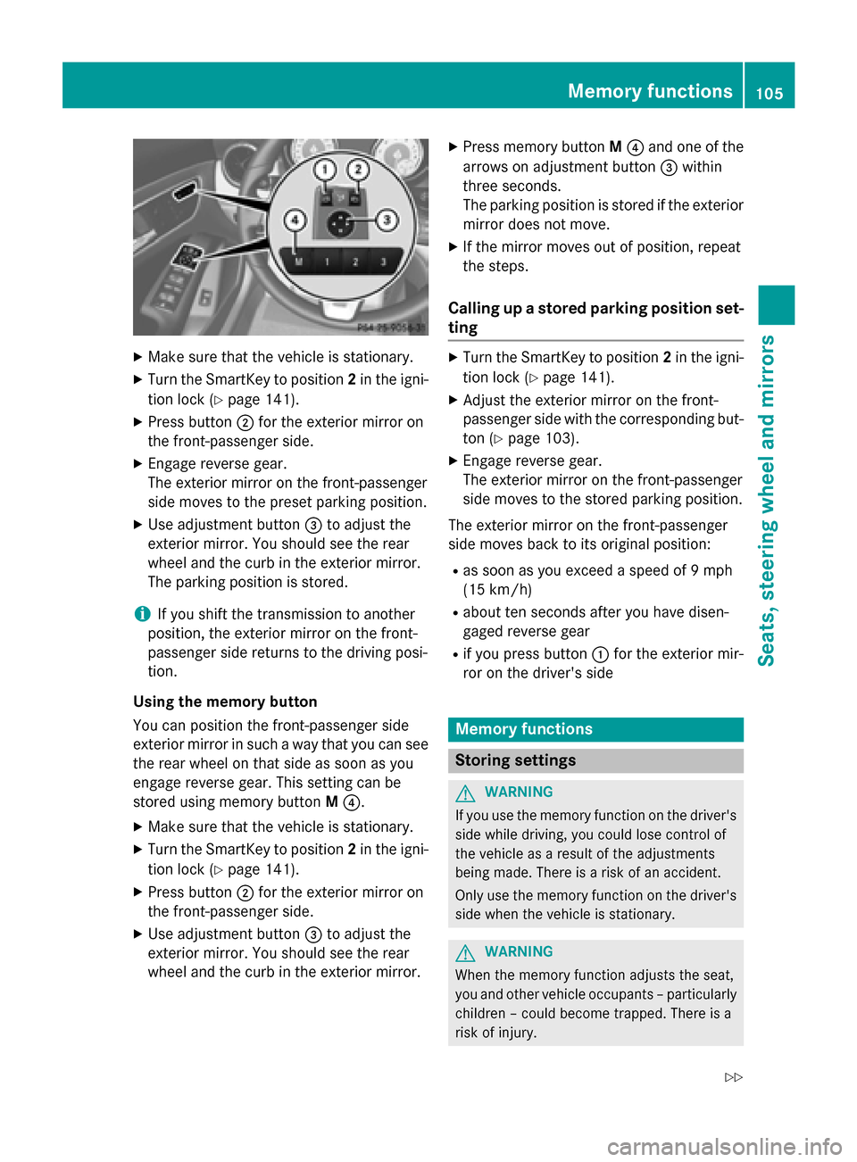
Make sure that the vehicle is stationary.
X Turn the SmartKey to position 2in the igni-
tion lock (Y page 141).
X Press button 0044for the exterior mirror on
the front-passenger side.
X Engage reverse gear.
The exterior mirror on the front-passenger
side moves to the preset parking position.
X Use adjustment button 0087to adjust the
exterior mirror. You should see the rear
wheel and the curb in the exterior mirror.
The parking position is stored.
i If you shift the transmission to another
position, the exterior mirror on the front-
passenger side returns to the driving posi-
tion.
Using the memory button
You can position the front-passenger side
exterior mirror in such a way that you can see
the rear wheel on that side as soon as you
engage reverse gear. This setting can be
stored using memory button M0085.
X Make sure that the vehicle is stationary.
X Turn the SmartKey to position 2in the igni-
tion lock (Y page 141).
X Press button 0044for the exterior mirror on
the front-passenger side.
X Use adjustment button 0087to adjust the
exterior mirror. You should see the rear
wheel and the curb in the exterior mirror. X
Press memory button M0085 and one of the
arrows on adjustment button 0087within
three seconds.
The parking position is stored if the exterior
mirror does not move.
X If the mirror moves out of position, repeat
the steps.
Calling up a stored parking position set- ting X
Turn the SmartKey to position 2in the igni-
tion lock (Y page 141).
X Adjust the exterior mirror on the front-
passenger side with the corresponding but-
ton (Y page 103).
X Engage reverse gear.
The exterior mirror on the front-passenger
side moves to the stored parking position.
The exterior mirror on the front-passenger
side moves back to its original position: R as soon as you exceed a speed of 9 mph
(15 km/h)
R about ten seconds after you have disen-
gaged reverse gear
R if you press button 0043for the exterior mir-
ror on the driver's side Memory functions
Storing settings
G
WARNING
If you use the memory function on the driver's side while driving, you could lose control of
the vehicle as a result of the adjustments
being made. There is a risk of an accident.
Only use the memory function on the driver's
side when the vehicle is stationary. G
WARNING
When the memory function adjusts the seat,
you and other vehicle occupants – particularly children – could become trapped. There is a
risk of injury. Memory functions
105Seats, steering wheel and mirrors
Z
Page 108 of 358
While the memory function is making adjust-
ments, make sure that no one has any body
parts in the sweep of the seat. If somebody
becomes trapped, immediately release the
memory function position button. The adjust- ment process is stopped. G
WARNING
Children could become trapped if they acti-
vate the memory function, particularly when
unattended. There is a risk of injury.
When leaving the vehicle, always take the
SmartKey with you and lock the vehicle. Never leave children unsupervised in the vehicle.
With the memory function, you can store up
to three different settings, e.g. for three dif-
ferent people.
The following settings are stored as a single
memory preset:
R position of the seat, backrest and head
restraint
R driver's side: position of the exterior mir-
rors on the driver's and front-passenger
sides X
Adjust the seat (Y page 99).
X Adjust the exterior mirror on the driver's
side (Y page 103).
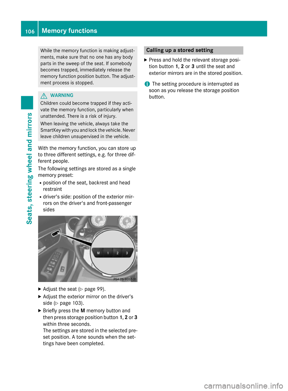
X Briefly press the Mmemory button and
then press storage position button 1,2or 3
within three seconds.
The settings are stored in the selected pre- set position. A tone sounds when the set-
tings have been completed. Calling up a stored setting
X Press and hold the relevant storage posi-
tion button 1,2or 3until the seat and
exterior mirrors are in the stored position.
i The setting procedure is interrupted as
soon as you release the storage position
button. 106
Memory functionsSeats, steering wheel and mirrors
Page 258 of 358
Useful information
i This Operator's manual describes all
models and all standard and optional equip- ment of your vehicle available at the time of
publication of the Operator's manual.
Country-specific differences are possible.
Please note that your vehicle may not be
equipped with all features described. This
also applies to safety-related systems and
functions.
i Read the information on qualified special-
ist workshops (Y page 26). Loading guidelines
G
WARNING
If objects, luggage or loads are not secured or not secured sufficiently, they could slip, tip
over or be flung around and thereby hit vehicle
occupants. There is a risk of injury, particu-
larly in the event of sudden braking or a sud-
den change in direction.
Always store objects so that they cannot be
flung around. Secure objects, luggage or
loads against slipping or tipping before the
journey. G
WARNING
Combustion engines emit poisonous exhaust
gases such as carbon monoxide. Exhaust
gases can enter the vehicle interior if the
trunk lid is open when the engine is running,
especially if the vehicle is in motion. There is a risk of poisoning.
Always switch off the engine before opening
the trunk lid. Never drive with the trunk lid
open. The handling characteristics of a laden vehi-
cle are dependent on the distribution of the
load within the vehicle. For this reason, you
should observe the following notes when
transporting a load:
R Never exceed the maximum permissible
gross vehicle weight or the gross axle
weight rating of the vehicle (including occu- pants). The values are specified on the vehi-
cle identification plate on the B-pillar of the
driver's door.
R The trunk is the preferred place to carry
objects.
R Position heavy loads as far forwards as pos-
sible and as low down in the trunk as pos-
sible.
R The load must not protrude above the
upper edge of the seat backrests.
R Always place the load against the rear or
front seat backrests. Make sure that the
seat backrests are securely locked into
place.
R Always place the load behind unoccupied
seats if possible.
R Use the cargo tie down rings and the parcel
nets to transport loads and luggage.
R Use cargo tie-down rings and fastening
materials appropriate for the weight and
size of the load.
R Secure the load with sufficiently strong and
wear-resistant tie-downs. Pad sharp edges
for protection. Stowage areas
Stowage space
Important safety notes G
WARNING
If you do not correctly store objects in the
vehicle interior, they can slip or be flung
around, thus striking vehicle occupants.
There is a risk of injury, especially when brak- ing or abruptly changing directions. 256
Stowage areasStowage and features
Page 304 of 358
Before handling the battery, touch the vehicle
body to remove any existing electrostatic
build-up.
The highly flammable gas mixture forms when
charging the battery as well as when jump-
starting.
Always make sure that neither you nor the
battery is electrostatically charged. A build-
up of electrostatic charge can be caused, for
example:
R by wearing clothing made from synthetic
fibers
R due to friction between clothing and seats
R if you push or pull the battery across the
carpet or other synthetic materials
R if you wipe the battery with a cloth G
WARNING
During the charging process, a battery produ- ces hydrogen gas. If a short circuit occurs or
sparks are created, the hydrogen gas can
ignite. There is a risk of an explosion.
R Make sure that the positive terminal of a
connected battery does not come into con-
tact with vehicle parts.
R Never place metal objects or tools on a bat-
tery.
R It is important that you observe the descri-
bed order of the battery terminals when
connecting and disconnecting a battery.
R When jump-starting, make sure that the
battery poles with identical polarity are
connected.
R It is particularly important to observe the
described order when connecting and dis-
connecting the jumper cables.
R Never connect or disconnect the battery
terminals while the engine is running. G
WARNING
Battery acid is caustic. There is a risk of injury. Avoid contact with the skin, eyes or clothing.
Do not inhale any battery gases. Do not lean
over the battery. Keep children away from batteries. Wash battery acid immediately with
water and seek medical attention. H
Environmental note Batteries contain dangerous
substances. It is against the
law to dispose of them with
the household rubbish. They
must be collected separately
and recycled to protect the
environment. Dispose of batteries in an
environmentally friendly
manner. Take discharged
batteries to a qualified spe-
cialist workshop or a special
collection point for used bat-
teries.
! Have the battery checked regularly at a
qualified specialist workshop.
Observe the service intervals in the Main-
tenance Booklet or contact a qualified spe-
cialist workshop for more information.
! You should have all work involving the
battery carried out at a qualified specialist
workshop. In the exceptional case that it is
necessary for you to disconnect the battery yourself, make sure that:
R you switch off the engine and remove the
SmartKey. Check that all the indicator
lamps in the instrument cluster are off.
Otherwise, electronic components, such
as the alternator, may be damaged.
R you first remove the negative terminal
clamp and then the positive terminal
clamp. Never swap the terminal clamps.
Otherwise, the vehicle's electronic sys-
tem may be damaged.
R on vehicles with automatic transmission,
the transmission is locked in position P
after disconnecting the battery. The vehi-
cle is secured against rolling away. You
can then no longer move the vehicle. 302
Battery (vehicle)Breakdown assistance
Page 320 of 358
Follow recommended tire inflation pressures
and check the pressure of all the tires includ-
ing the spare wheel:
R monthly, at least
R if the load changes
R before beginning a long journey
R under different operating conditions, e.g.
off-road driving
If necessary, correct the tire pressure.
Use a suitable pressure gauge to check the
tire pressure. The outer appearance of a tire
does not permit any reliable conclusion about the tire pressure. On vehicles equipped with
the electronic tire pressure monitor, the tire
pressure can be checked in the on-board
computer.
The recommended tire pressures for the tires
mounted at the factory can be found on the
labels described here.
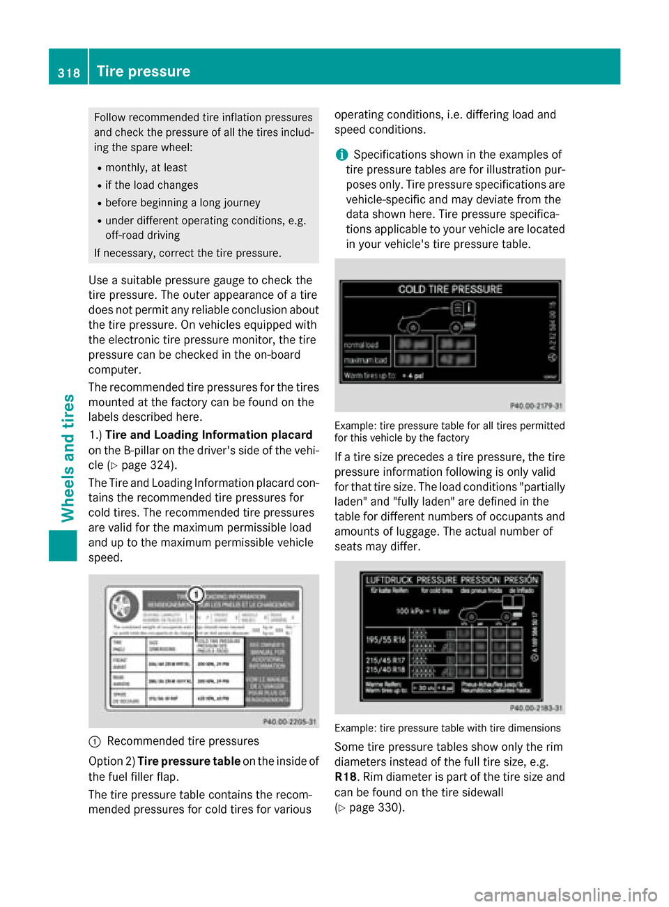
1.) Tire and Loading Information placard
on the B-pilla ron the driver's side of the vehi-
cle (Y page 324).
The Tire and Loading Information placard con-
tains the recommended tire pressures for
cold tires. The recommended tire pressures
are valid for the maximum permissible load
and up to the maximum permissible vehicle
speed. 0043
Recommended tire pressures
Option 2) Tire pressure table on the inside of
the fuel filler flap.
The tire pressure table contains the recom-
mended pressures for cold tires for various operating conditions, i.e. differing load and
speed conditions.
i Specifications shown in the examples of
tire pressure tables are for illustration pur-
poses only. Tire pressure specifications are
vehicle-specific and may deviate from the
data shown here. Tire pressure specifica-
tions applicable to your vehicle are located in your vehicle's tire pressure table. Example: tire pressure table for all tires permitted
for this vehicle by the factory
If a tire size precedes a tire pressure, the tire pressure information following is only valid
for that tire size. The load conditions "partially
laden" and "fully laden" are defined in the
table for different numbers of occupants and amounts of luggage. The actual number of
seats may differ. Example: tire pressure table with tire dimensions
Some tire pressure tables show only the rim
diameters instead of the full tire size, e.g.
R18 . Rim diameter is part of the tire size and
can be found on the tire sidewall
(Y page 330). 318
Tire pressureWheels and tires