Key MERCEDES-BENZ CLA-Class 2016 C117 Owners Manual
[x] Cancel search | Manufacturer: MERCEDES-BENZ, Model Year: 2016, Model line: CLA-Class, Model: MERCEDES-BENZ CLA-Class 2016 C117Pages: 374, PDF Size: 8.19 MB
Page 293 of 374
only light up yellow after ten seconds have
elapsed.
XRelease button;,=or?. Indicator
lamp :flashes yellow.
XTo program the remote control: point
garage door remote control Atowards
buttons ;to? on the rear-view mirror at
a distance of 2 to 8 inches (5 to 20 cm).
XPress and hold button Bon remote control
A until indicator lamp :lights up green.
When indicator lamp :lights up green:
programing is finished.
When indicator lamp :flashes green: pro-
graming was successful. The next step is to
synchronize the rolling code (
Ypage 291).
XRelease button Bon remote control Afor
the garage door drive system.
If indicator lamp :lights up red: repeat the
programing procedure for the correspond-
ing button on the rear-view mirror. When
doing so, vary the distance between remote
control Aand the rear-view mirror.
The required distance between remote
control Aand the integrated garage door
opener depends on the garage door drive
system. Several attempts might be neces-
sary. You should test every position for at
least 25 seconds before trying another
position.
Synchronizing the rolling code
Pay attention to the "Important safety notes"
(
Ypage 290).
If the garage door system uses a rolling code,
you will also have to synchronize the garage
door system with the integrated garage door
opener in the rear-view mirror. To do this you
will need to use the programing button on the
control panel of the door drive. The program- ing button may be positioned in different pla-
ces depending on the manufacturer. It is usu-
ally located on the door drive unit on the
garage ceiling.
Familiarize yourself with the garage door
drive operating instructions, e.g. under "Pro- graming of additional remote controls",
before carrying out the following steps.
Your vehicle must be within reach of the
garage door or gate opener drive. Make sure
that neither your vehicle nor any persons/
objects are present within the sweep of the
door or gate.
XTurn the SmartKey to position
2in the igni-
tion lock (
Ypage 147).
XGet out of the vehicle.
XPress the programing button on the door
drive unit.
Usually , you now have 30 secon
ds to ini-
tiate the next step.
XGet into the vehicle.
XPress previously programed button ;,=
or ? on the integrated garage door opener
repeatedly until the door closes.
The rolling code synchronization is then
complete.
Notes on programing the remote control
Canadian radio frequency laws require a
"break" (or interruption) of the transmission
signals after broadcasting for a few seconds.
Therefore, these signals may not last long
enough for the integrated garage door
opener. The signal is not recognized during
programing. Comparable with Canadian law,
some U.S. garage door openers also feature a
"break".
Proceed as follows:
Rif you live in Canada
Rif you have difficulties programing the
garage door opener (regardless of where
you live) when using the programing steps.
XPress and hold one of buttons ;to? on
the integrated garage door opener.
After a short time, indicator lamp :lights
up yellow.
XRelease the button.
Indicator lamp :flashes yellow.
XPress button Bof garage door remote
control Afor two seconds, then release it
for two seconds.
Features291
Stowage and features
Z
Page 294 of 374
XPress buttonBagain for two seconds.
XRepeat this sequence on button Bof
remote control Auntil indicator lamp :
lights up green.
When indicator lamp :lights up green:
programing is finished.
When indicator lamp :flashes green: pro-
graming was successful. The next step is to
synchronize the rolling code.
XRelease button Bof remote control Aof
the garage door drive.
If indicator lamp :lights up red: repeat the
programing process for the corresponding
button on the rear-view mirror. When doing
so, vary the distance between remote con-
trol Aand the rear-view mirror.
The required distance between remote
control Aand the integrated garage door
opener depends on the garage door drive
system. Several attempts might be neces-
sary. You should test every position for at
least 25 seconds before trying another
position.
Problems when programing
If you experience problems programing the
integrated garage door opener on the rear-
view mirror, take note of the following instruc-
tions:
RCheck the transmitter frequency used by
garage door drive remote control Aand
whether it is supported. The transmitter
frequency can usually be found on the back
of the garage door drive remote control.
The integrated garage door opener is com-
patible with devices that have units which
operate in the frequency range of 280 to
433 MHz.
RReplace the batteries in garage door
remote control A. This increases the like-
lihood that garage door remote control A
will transmit a strong and precise signal to the integrated garage door opener.
RWhen programing, hold remote control A
at varying distances and angles from the
button which you are programing. Try vari- ous angles at a distance between 2and
12 inches (5to 30 cm) or at the same angle
but at varying distances.
RIf another remote control is available for the
same garage door drive, repeat the same
programing steps with this remote control.
Before performing these steps, make sure
that new batteries have been installed in
garage door drive remote
control
A
.
RNote that some remote controls only trans-
mit for a limited amount of time (the indi-
cator lamp on the remote control goes out).
Press button Bon remote control Aagain
before transmission ends.
RAlign the antenna cable of the garage door
opener unit. This can improve signal recep-
tion/transmission.
Opening/closing the garage door
After it has been programmed, the integrated
garage door opener assumes the function of
the garage door system's remote control.
Please also read the operating instructions
for the garage door system.
XTurn the SmartKey to position 2in the igni-
tion lock (
Ypage 147).
XPress button ;,=or? that has been
programmed to operate the garage door.
Garage door system with a fixed code: indi-
cator lamp :lights up green.
Garage door system with a rolling code:
indicator lamp :flashes green.
The transmitter will transmit a signal as
long as the button is pressed. The trans-
mission is halted after a maximum of ten
seconds and indicator lamp :lights up
yellow.
XPress button ;,=or? again if neces-
sary.
Clearing the memory
Make sure that you clear the memory of the
integrated garage door opener before selling
the vehicle.
292Features
Stowage and features
Page 295 of 374
XTurn the SmartKey to position2in the igni-
tion lock (
Ypage 147).
XPress and hold buttons ;and ?.
The indicator lamp initially lights up yellow
and then green.
XRelease buttons ;and ?.
The memory of the integrated garage door
opener in the rear-view mirror is cleared.
Compass
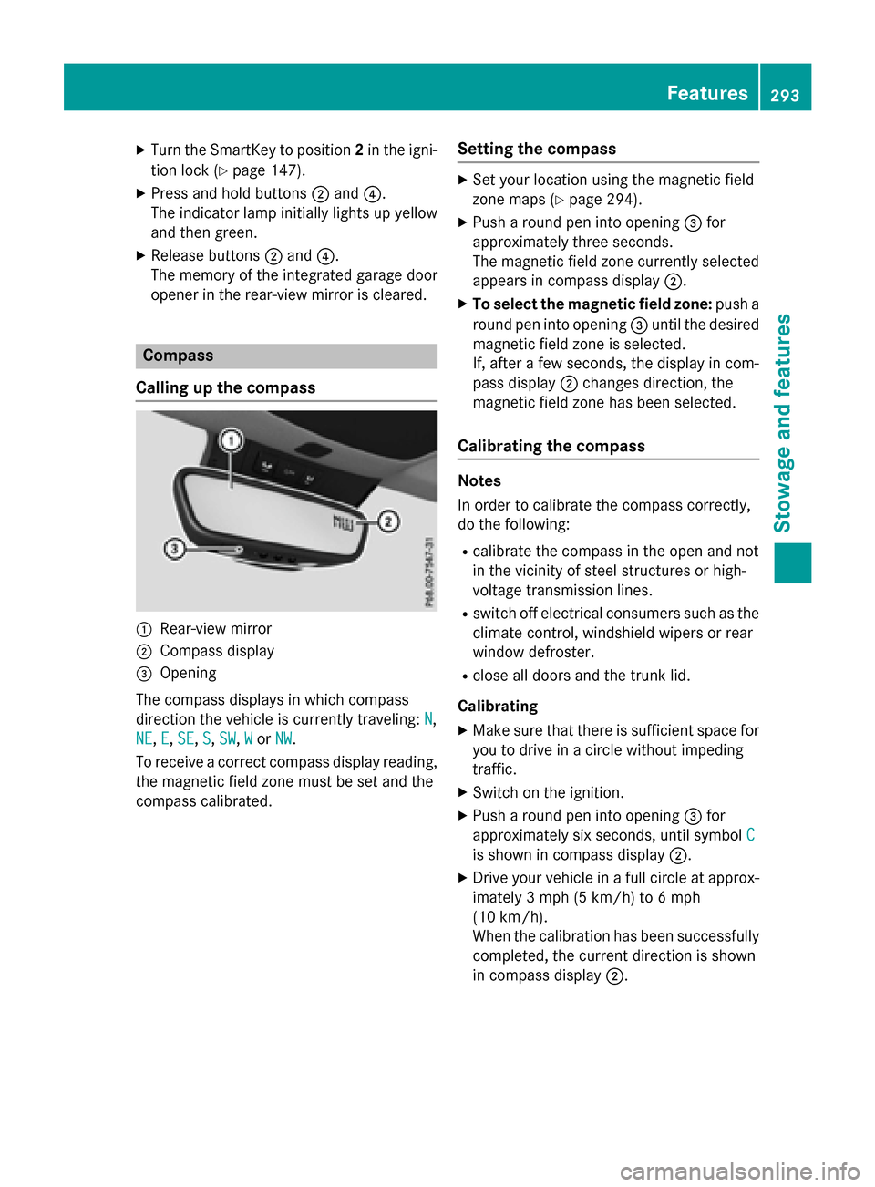
Calling up the compass
:Rear-view mirror
;Compass display
=Opening
The compass displays in which compass
direction the vehicle is currently traveling: N
,
NE
, E,SE,S,SW,Wor NW.
To receive a correct compass display reading, the magnetic field zone must be set and the
compass calibrated.
Setting the compass
XSet your location using the magnetic field
zone maps (
Ypage 294).
XPush a round pen into opening =for
approximately three seconds.
The magnetic field zone currently selected
appears in compass display ;.
XTo select the magnetic field zone: push a
round pen into opening =until the desired
magnetic field zone is selected.
If, after a few seconds, the display in com-
pass display ;changes direction, the
magnetic field zone has been selected.
Calibrating the compass
Notes
In order to calibrate the compass correctly,
do the following:
Rcalibrate the compass in the open and not
in the vicinity of steel structures or high-
voltage transmission lines.
Rswitch off electrical consumers such as the
climate control, windshield wipers or rear
window defroster.
Rclose all doors and the trunk lid.
Calibrating
XMake sure that there is sufficient space for
you to drive in a circle without impeding
traffic.
XSwitch on the ignition.
XPush a round pen into opening =for
approximately six seconds, until symbol C
is shown in compass display;.
XDrive your vehicle in a full circle at approx-
imately 3 mph (5 km/h) to 6 mph
(10 km/h).
When the calibration has been successfully
completed, the current direction is shown
in compass display;.
Features293
Stowage and features
Z
Page 301 of 374
Example: engine oil cap
XTurn cap:counter-clockwise and remove
it.
XAdd engine oil.
If the oil level is at or below the MIN mark on
the oil dipstick, add 1.1 US qt (1.0 l)of
engine oil.
XReplace cap :on the filler neck and turn
clockwise.
Ensure that the cap locks into place
securely.
XCheck the oil level again with the oil dip-
stick (
Ypage 298).
Further information on engine oil
(
Ypage 368).
Checking and adding other service
products
Checking coolant level
GWARNING
The cooling system is pressurized, particularly
when the motor is warm. If you open the cap,
you could be scalded if hot coolant sprays out.
There is a risk of injury.
Let the engine cool down before you open the
cap. Wear gloves and eye protection. Slowly
open the cap to relieve pressure.
!The coolant may only be checked and cor-
rected when the engine is cool (coolant
temperature below 104 ‡ (40 †). Check-
ing the coolant when the coolant tempera-
ture is above 104 ‡ (40 †) may result in
damage to the engine or to the engine cool-
ing system.
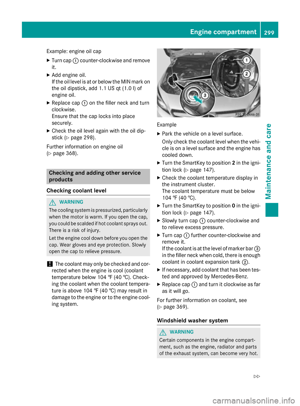
Example
XPark the vehicle on a level surface.
Only check the coolant level when the vehi-
cle is on a level surface and the engine has cooled down.
XTurn the SmartKey to position 2in the igni-
tion lock (
Ypage 147).
XCheck the coolant temperature display in
the instrument cluster.
The coolant temperature must be below
104 ‡ (40 †).
XTurn the SmartKey to position 0in the igni-
tion lock (
Ypage 147).
XSlowly turn cap :counter-clockwise and
to relieve excess pressure.
XTurn cap :further counter-clockwise and
remove it.
If the coolant is at the level of marker bar =
in the filler neck when cold, there is enough
coolant in coolant expansion tank ;.
XIf necessary, add coolant that has been tes-
ted and approved by Mercedes-Benz.
XReplace cap:and turn it clockwise as far
as it will go.
For further information on coolant, see
(
Ypage 369).
Windshield washer system
GWARNING
Certain components in the engine compart-
ment, such as the engine, radiator and parts
of the exhaust system, can become very hot.
Engine compartment299
Maintenance and care
Z
Page 308 of 374

Cleaning the rear view camera
!Do not clean the camera lens and the area
around the rear view camera with a power
washer.
XMake sure that the vehicle is stationary and that the SmartKey is in position 2in the
ignition lock.
XOpening the camera cover for cleaning with Audio 20 or COMAND; see the separate
operating instructions.
XTo clean the rear view camera: use clear
water and a soft cloth to clean camera
lens :.
Cleaning the exhaust pipes
GWARNING
The exhaust tail pipe and tail pipe trim can
become very hot. If you come into contact
with these parts of the vehicle, you could burn
yourself. There is a risk of injury.
Always be particularly careful around the
exhaust tail pipe and the tail pipe trim. Allow
these components to cool down before touch-
ing them.
!Do not clean the exhaust pipe with acid-
based cleaning agents, such as bathroom
cleaner or wheel cleaner.
!Mercedes-AMG vehicles with black
exhaust pipes: the black-chrome tailpipe
finishers should not be polished with a
chrome polish. They will otherwise lose
their black sheen. For optimal care, the
faceplates should be rubbed with a lightly oiled cloth after every car wash. Commer-
cially available engine and care oils are
suitable for this.
For heavier soiling, you can apply a fine
paintwork polish with a microfiber cloth.
Remove the excess polish residue after pol-
ishing.
Impurities combined with the effects of road
grit and corrosive environmental factors may
cause flash rust to form on the surface. You
can restore the original shine of the exhaust
pipe by cleaning it regularly, especially in win-
ter and after washing.
XClean the exhaust pipe with a care product
tested and approved by Mercedes-Benz.
Interior care
Cleaning the display
!For cleaning, do not use any of the fol-
lowing:
Ralcohol-based thinner or gasoline
Rabrasive cleaning agents
Rcommercially-available household clean-
ing agents
These may damage the display surface. Do not put pressure on the display surface
when cleaning. This could lead to irrepara-
ble damage to the display.
XBefore cleaning the display, make sure thatit is switched off and has cooled down.
XClean the display surface using a commer-
cially available microfiber cloth and
TFT/LCD display cleaner.
XDry the display surface using a dry micro-
fiber cloth.
Cleaning the plastic trim
GWARNING
Care products and cleaning agents containing solvents cause surfaces in the cockpit to
become porous. As a result, plastic parts may
306Care
Maintenance and care
Page 313 of 374
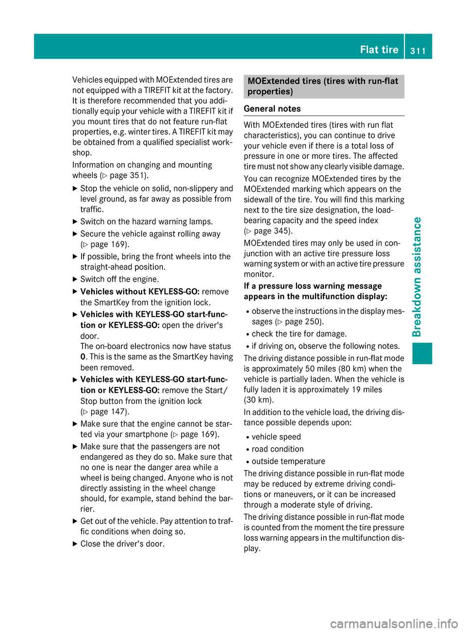
Vehicles equipped with MOExtended tires are
not equipped with a TIREFIT kit at the factory.
It is therefore recommended that you addi-
tionally equip your vehicle with a TIREFIT kit ifyou mount tires that do not feature run-flat
properties, e.g. winter tires. A TIREFIT kit may
be obtained from a qualified specialist work-
shop.
Information on changing and mounting
wheels (
Ypage 351).
XStop the vehicle on solid, non-slippery and
level ground, as far away as possible from
traffic.
XSwitch on the hazard warning lamps.
XSecure the vehicle against rolling away
(
Ypage 169).
XIf possible, bring the front wheels into the
straight-ahead position.
XSwitch off the engine.
XVehicles without KEYLESS-GO: remove
the SmartKey from the ignition lock.
XVehicles with KEYLESS-GO start-func-
tion or KEYLESS-GO: open the driver's
door.
The on-board electronics now have status
0. This is the same as the SmartKey having
been removed.
XVehicles with KEYLESS-GO start-func-
tion or KEYLESS-GO: remove the Start/
Stop button from the ignition lock
(
Ypage 147).
XMake sure that the engine cannot be star-
ted via your smartphone (
Ypage 169).
XMake sure that the passengers are not
endangered as they do so. Make sure that
no one is near the danger area while a
wheel is being changed. Anyone who is not directly assisting in the wheel change
should, for example, stand behind the bar-
rier.
XGet out of the vehicle. Pay attention to traf-
fic conditions when doing so.
XClose the driver's door.
MOExtended tires (tires with run-flat
properties)
General notes
With MOExtended tires (tires with run flat
characteristics), you can continue to drive
your vehicle even if there is a total loss of
pressure in one or more tires. The affected
tire must not show any clearly visible damage.
You can recognize MOExtended tires by the
MOExtended marking which appears on the
sidewall of the tire. You will find this marking next to the tire size designation, the load-
bearing capacity and the speed index
(
Ypage 345).
MOExtended tires may only be used in con-
junction with an active tire pressure loss
warning system or with an active tire pressure
monitor.
If a pressure loss warning message
appears in the multifunction display:
Robserve the instructions in the display mes-
sages (
Ypage 250).
Rcheck the tire for damage.
Rif driving on, observe the following notes.
The driving distance possible in run-flat mode
is approximately 50 miles (80 km) when the
vehicle is partially laden. When the vehicle is
fully laden it is approximately 19 miles
(30 km).
In addition to the vehicle load, the driving dis-
tance possible depends upon:
Rvehicle speed
Rroad condition
Routside temperature
The driving distance possible in run-flat mode
may be reduced by extreme driving condi-
tions or maneuvers, or it can be increased
through a moderate style of driving.
The driving distance possible in run-flat mode
is counted from the moment the tire pressure loss warning appears in the multifunction dis-
play.
Flat tire311
Breakdown assistance
Page 315 of 374
!Do not operate the tire inflation compres-
sor for longer than ten minutes at a time
without a break. It may otherwise overheat.
The tire inflation compressor can be oper-
ated again once it has cooled down.
Comply with the manufacturer’s safety
instructions on the sticker on the tire inflation
compressor.
Using the TIREFIT kit
XDo not remove any foreign objects which
have penetrated the tire, e.g. screws or
nails.
XRemove the tire sealant bottle, the accom-
panying TIREFIT sticker and the tire infla-
tion compressor from the stowage well
underneath the trunk floor (
Ypage 310).
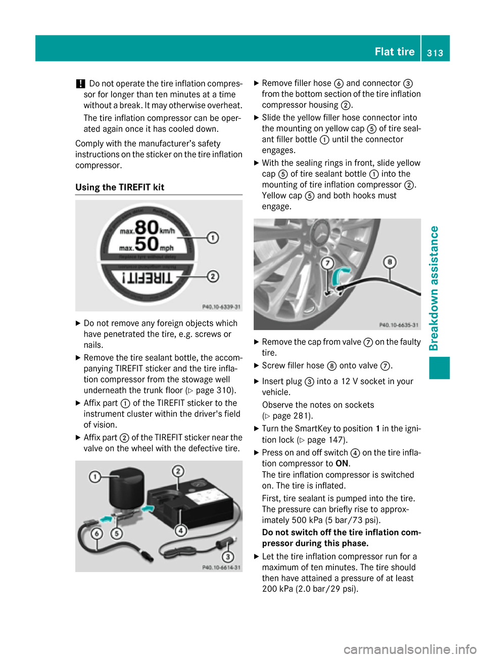
XAffix part :of the TIREFIT sticker to the
instrument cluster within the driver's field
of vision.
XAffix part ;of the TIREFIT sticker near the
valve on the wheel with the defective tire.
XRemove filler hose Band connector =
from the bottom section of the tire inflation
compressor housing ;.
XSlide the yellow filler hose connector into
the mounting on yellow cap Aof tire seal-
ant filler bottle :until the connector
engages.
XWith the sealing rings in front, slide yellow
cap Aof tire sealant bottle :into the
mounting of tire inflation compressor ;.
Yellow cap Aand both hooks must
engage.
XRemove the cap from valve Con the faulty
tire.
XScrew filler hose Donto valve C.
XInsert plug =into a 12 V socket in your
vehicle.
Observe the notes on sockets
(
Ypage 281).
XTurn the SmartKey to position 1in the igni-
tion lock (
Ypage 147).
XPress on and off switch ?on the tire infla-
tion compressor to ON.
The tire inflation compressor is switched
on. The tire is inflated.
First, tire sealant is pumped into the tire.
The pressure can briefly rise to approx-
imately 500 kPa (5 bar/73 psi).
Do not switch off the tire inflation com-
pressor during this phase.
XLet the tire inflation compressor run for a
maximum of ten minutes. The tire should
then have attained a pressure of at least
200 kPa (2.0 bar/29 psi).
Flat tire313
Breakdown assistance
Z
Page 318 of 374
should have all work involving the battery car-ried out at a qualified specialist workshop.
For further information about ABS and ESP®,
see (
Ypage 65) and (Ypage 69).
GWARNING
Electrostatic build-up can lead to the creation of sparks, which could ignite the highly explo-
sive gases of a battery. There is a risk of an
explosion.
Before handling the battery, touch the vehicle
body to remove any existing electrostatic
build-up.
The highly flammable gas mixture forms when
charging the battery as well as when jump-
starting.
Always make sure that neither you nor the
battery is electrostatically charged. A build-
up of electrostatic charge can be caused, for
example:
Rby wearing clothing made from synthetic
fibers
Rdue to friction between clothing and seats
Rif you push or pull the battery across the
carpet or other synthetic materials
Rif you wipe the battery with a cloth
GWARNING
During the charging process, a battery produ-
ces hydrogen gas. If a short circuit occurs or
sparks are created, the hydrogen gas can
ignite. There is a risk of an explosion.
RMake sure that the positive terminal of a
connected battery does not come into con- tact with vehicle parts.
RNever place metal objects or tools on a bat-
tery.
RIt is important that you observe the descri-
bed order of the battery terminals when
connecting and disconnecting a battery.
RWhen jump-starting, make sure that the
battery poles with identical polarity are
connected.
RIt is particularly important to observe the
described order when connecting and dis-
connecting the jumper cables.
RNever connect or disconnect the battery
terminals while the engine is running.
GWARNING
Battery acid is caustic. There is a risk of injury.
Avoid contact with skin, eyes or clothing. Do
not inhale any battery gases. Do not lean over
the battery. Keep children away from batter-
ies. Wash away battery acid immediately with
plenty of clean water and seek medical atten-
tion.
HEnvironmental note
Batteries contain dangerous
substances. It is against the
law to dispose of them with
the household rubbish. They
must be collected separately and recycled to protect the
environment.
Dispose of batteries in an
environmentally friendly
manner. Take discharged
batteries to a qualified spe-
cialist workshop or a special
collection point for used bat-
teries.
!Have the battery checked regularly at a
qualified specialist workshop.
Observe the service intervals in the Main-
tenance Booklet or contact a qualified spe-
cialist workshop for more information.
!You should have all work involving the
battery carried out at a qualified specialist
workshop. In the exceptional case that it is
necessary for you to disconnect the battery
yourself, make sure that:
Ryou switch off the engine and remove the
key. On vehicles with KEYLESS-GO,
ensure that the ignition is switched off.
Check that all the indicator lamps in the
instrument cluster are off. Otherwise,
316Battery (vehicle)
Breakdown assistance
Page 319 of 374
electronic components, such as the
alternator, may be damaged.
Ryou first remove the negative terminal
clamp and then the positive terminal
clamp. Never swap the terminal clamps.
Otherwise, the vehicle's electronic sys-
tem may be damaged.
Rin vehicles with automatic transmission,
the transmission is locked in positionP
after disconnecting the battery. The vehi-
cle is secured against rolling away. You
can then no longer move the vehicle.
The battery and the cover of the positive
terminal clamp must be installed securely
during operation.
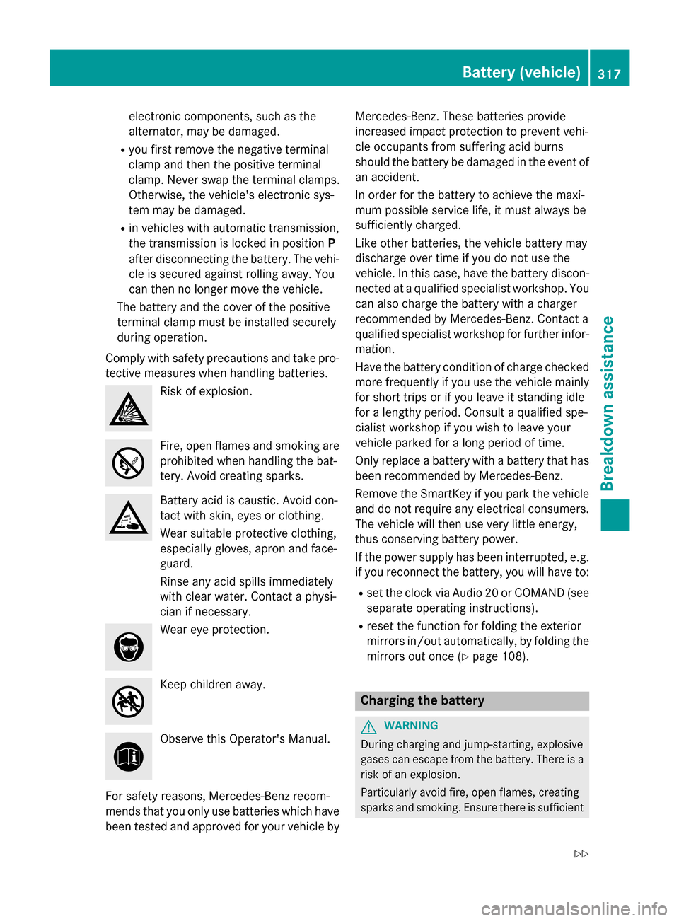
Comply with safety precautions and take pro- tective measures when handling batteries.
Risk of explosion.
Fire, open flames and smoking are
prohibited when handling the bat-
tery. Avoid creating sparks.
Battery acid is caustic. Avoid con-
tact with skin, eyes or clothing.
Wear suitable protective clothing,
especially gloves, apron and face-
guard.
Rinse any acid spills immediately
with clear water. Contact a physi-
cian if necessary.
Wear eye protection.
Keep children away.
Observe this Operator's Manual.
For safety reasons, Mercedes-Benz recom-
mends that you only use batteries which have
been tested and approved for your vehicle by Mercedes-Benz. These batteries provide
increased impact protection to prevent vehi-
cle occupants from suffering acid burns
should the battery be damaged in the event of
an accident.
In order for the battery to achieve the maxi-
mum possible service life, it must always be
sufficiently charged.
Like other batteries, the vehicle battery may
discharge over time if you do not use the
vehicle. In this case, have the battery discon- nected at a qualified specialist workshop. You
can also charge the battery with a charger
recommended by Mercedes-Benz. Contact a
qualified specialist workshop for further infor- mation.
Have the battery condition of charge checked
more frequently if you use the vehicle mainly
for short trips or if you leave it standing idle
for a lengthy period. Consult a qualified spe-
cialist workshop if you wish to leave your
vehicle parked for a long period of time.
Only replace a battery with a battery that has
been recommended by Mercedes-Benz.
Remove the SmartKey if you park the vehicle
and do not require any electrical consumers.
The vehicle will then use very little energy,
thus conserving battery power.
If the power supply has been interrupted, e.g.
if you reconnect the battery, you will have to:
Rset the clock via Audio 20 or COMAND (see
separate operating instructions).
Rreset the function for folding the exterior
mirrors in/out automatically, by folding the
mirrors out once (
Ypage 108).
Charging the battery
GWARNING
During charging and jump-starting, explosive
gases can escape from the battery. There is a risk of an explosion.
Particularly avoid fire, open flames, creating
sparks and smoking. Ensure there is sufficient
Battery (vehicle)317
Breakdown assistance
Z
Page 322 of 374
Do not start the vehicle using a rapid charging device. If your vehicle's battery is discharged,
the engine can be jump-started from another vehicle or from a second battery using jumper
cables. Observe the following points:
RThe battery is not accessible in all vehicles. If the other vehicle's battery is not accessible,
jump-start the vehicle using a second battery or a jump-starting device.
RYou may only jump-start the vehicle when the engine and exhaust system are cold.
RDo not start the engine if the battery is frozen. Let the battery thaw first.
ROnly jump-start from batteries with a 12 V voltage rating.
ROnly use jumper cables that are not damaged and have a sufficient cross-section and insu-
lated terminal clamps.
RMake sure that the two vehicles do not touch.
Make sure that:
Rthe jumper cables are not damaged.
Rnon-insulated parts of the terminal clamps do not come into contact with other metal parts
while the jumper cables are connected to the battery.
RThe jumper cables cannot come into contact with parts which can move when the engine is
running, such as the V-belt pulley or the fan.
XSecure the vehicle by applying the electric parking brake.
XShift the transmission to position P.
XTurn the SmartKey to position 0in the ignition lock and remove it.
XSwitch off all electrical consumers, e.g. rear window defroster, lighting, etc.
XOpen the hood.
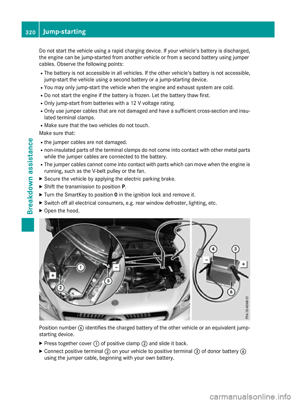
Position number Bidentifies the charged battery of the other vehicle or an equivalent jump-
starting device.
XPress together cover :of positive clamp ;and slide it back.
XConnect positive terminal ;on your vehicle to positive terminal =of donor battery B
using the jumper cable, beginning with your own battery.
320Jump-starting
Breakdown assistance