trailer MERCEDES-BENZ CLA-Class 2016 C117 Owner's Manual
[x] Cancel search | Manufacturer: MERCEDES-BENZ, Model Year: 2016, Model line: CLA-Class, Model: MERCEDES-BENZ CLA-Class 2016 C117Pages: 374, PDF Size: 8.19 MB
Page 12 of 374
ESP®(Electronic Stability Pro-
gram)
AMG menu (on-board computer) .. .224
Characteristics ................................. 69
Deactivating/activating (button
in Mercedes-AMG vehicles) ............. 70
Deactivating/activating (except
Mercedes‑AMG vehicles) ................. 70
Deactivating/activating (on-
board computer, except
Mercedes-AMG vehicles) ...............2 19
Display message ............................ 228
Function/notes ................................ 69
General notes .................................. 69
Important safety information ........... 69
Trailer stabilization ........................... 72
Warning lamp ................................. 263
ETS/4ETS (Electronic Traction Sys-
tem) ...................................................... 69
Exhaust
see Exhaust pipe
Exhaust check ................................... 173
Exhaust pipe
Cleaning ......................................... 306
Exterior lighting
Cleaning ......................................... 305
see Lights
Exterior mirrors
Adjusting ....................................... 107
Dipping (automatic) ....................... 108
Folding in when locking (on-board
computer) ...................................... 223
Folding in/out (automatically) ....... 108
Folding in/out (electrically) ........... 107
Out of position (troubleshooting) ... 108
Setting ........................................... 108
Storing settings (memory func-
tion) ............................................... 110
Storing the parking position .......... 109
Eyeglasses compartment ................. 273
F
Filler cap
see Refueling
Flat tire
MOExtended tires .......................... 311
Preparing the vehicle ..................... 310 TIREFIT kit ...................................... 312
Floormats ........................................... 294
Fog lamps
Switching on/off ........................... 115
Frequencies
Mobile phone ................................. 362
Two-way radio ................................ 362
Front fog lamps
Display message ............................ 241
Switching on/off ........................... 115
Fuel
Additives ........................................ 367
Consumption information .............. 367
Consumption statistics .................. 214
Displaying the current consump-
tion ................................................ 214
Displaying the range ...................... 214
Driving tips .................................... 173
E10 ................................................ 366
Flexible fuel vehicles ...................... 367
Fuel gauge ....................................... 31
Grade (gasoline) ............................ 366
Important safety notes .................. 365
Problem (malfunction) ................... 169
Refueling ........................................ 167
Tank content/reserve fuel ............. 366
Fuel filler flap
Opening ......................................... 168
Fuel level
Calling up the range (on-board
computer) ...................................... 214
Fuel tank
Capacity ........................................ 366
Problem (malfunction) ................... 169
Fuses
Allocation chart ............................. 326
Before changing ............................. 325
Fuse box in the engine compart-
ment .............................................. 325
Fuse box in the front-passenger
footwell .......................................... 326
Important safety notes .................. 325G
Garage door openerClearing the memory ..................... 292
General notes ................................ 289
10Index
Page 20 of 374
Warning lamp ................................. 270
Warning message .......................... 338
TIREFIT kit .......................................... 312
Tire pressure not reached .............. 314
Tire pressure reached .................... 314
Tires
Aspect ratio (definition) ................. 350
Average weight of the vehicle
occupants (definition) .................... 349
Bar (definition) ...............................3 48
Changing a wheel .......................... 351
Characteristics .............................. 348
Checking ........................................ 329
Curb weight (definition) ................. 350
Definition of terms ......................... 348
Direction of rotation ...................... 351
Display message ............................ 250
Distribution of the vehicle occu-
pants (definition) ............................ 351
DOT (Department of Transporta-
tion) (definition) ............................. 349
DOT, Tire Identification Number
(TIN) ............................................... 348
GAWR (Gross Axle Weight Rating)
(definition) ..................................... 349
General notes ................................ 355
GVW (Gross Vehicle Weight) (def-
inition) ........................................... 349
GVWR (Gross Vehicle Weight Rat-
ing) (definition) .............................. 349
Important safety notes .................. 328
Increased vehicle weight due to
optional equipment (definition) ...... 349
Information on driving .................... 328
Kilopascal (kPa) (definition) ........... 349
Labeling (overview) ........................ 345
Load bearing index (definition) ...... 350
Load index ..................................... 347
Load index (definition) ................... 349
M+S tires ....................................... 330
Maximum load on a tire (defini-
tion) ............................................... 350
Maximum loaded vehicle weig ht
(
definition) ..................................... 349
Maximum permissible tire pres-
sure (definition) ............................. 350
Maximum tire load ......................... 347
Maximum tire load (definition) ....... 350 MOExtended tires .......................... 330
Optional equipment weight (defi-
nition) ............................................ 350
PSI (pounds per square inch) (def-
inition) ........................................... 350
Replacing ....................................... 351
Service life ..................................... 330
Sidewall (definition) ....................... 350
Speed rating (definition) ................ 349
Storing ........................................... 351
Structure and characteristics
(definition) ..................................... 348
Summer tires ................................. 330
Temperature .................................. 344
TIN (Tire Identification Number)
(definition) ..................................... 350
Tire bead (definition) ...................... 350
Tire pressure (definition) ................ 350
Tire pressures (recommended) ...... 349
Tire size (data) ............................... 355
Tire size designation, load-bearing
capacity, speed rating .................... 345
Tire tread ....................................... 329
Tire tread (definition) ..................... 350
Total load limit (definition) ............. 351
Traction ......................................... 344
Traction (definition) ....................... 350
Tread wear ..................................... 344
Uniform Tire Quality Grading
Standards ...................................... 343
Uniform Tire Quality Grading
Standards (definition) .................... 349
Wear indicator (definition) ............. 350
Wheel and tire combination ........... 357
Wheel rim (definition) .................... 349
see Flat tire
Top Tether ............................................ 61
Tow-starting
Emergency engine starting ............ 325
Important safety notes .................. 321
Installing the towing eye ................ 322
Removing the towing eye ............... 323
Towing a trailer
ESP®(Electronic Stability Pro-
gra m) ............................................... 72
To
wing away
Important safety guidelines ........... 321
Installing the towing eye ................ 322
18Index
Page 74 of 374
RCOLLISION PREVENTION AS SIST isno lon-
ger available; nor is itactivated ifyou brake
firmly with assistance from ESP
®.
RESP®still provides support when you brake
firmly.
ESP®trailer stabilization
General info rmation
If your veh icle/trailer combination begins to
swerve, ESP
®assists you inthis situation.
ESP®slows the vehicle down bybraking and
limit ing the engine output unt ilthe vehicle/
trailer co mbination has stabilized.
Import ant safety notes
GWARNIN G
If road and weather condition sare poor ,
trailer stabilization will no tbe able to preven t
th evehicle/traile rcombination from swerv-
ing .Trailers wit h ahigh cente rof gravity can
tip ove rbefore ES P
®can detect this. Ther eis
a ris kof an accident.
Always adapt your driving style to th eprevail-
ing road and weather conditions.
If your veh icle with trailer (vehicle/trailer
co mbin ation) begins to lurch, you can only
stabiliz e the vehicle /trailer combination by
depr essing the brake firmly.
ESP
®trailer stabiliz ation is active above
speeds of about 65 km/h.
ESP
®trailer stabilization does not work if
ESP®is deactivated or disabled because of a
malfunction.
EBD (electronic brake force distribu-
tion)
General information
EBD mon itors and controls the brake pres-
sure on the rear wheels to improve driving
stabilit ywhile braking.
Important safety notes
iObserve the "Important safety notes" sec-
tion (
Ypage 65).
GWARNIN G
If EB Dis malfunctioning, th erear wheels can
lock, e.g. under full braking .This increases th e
ris kof skiddin gand an accident.
You should therefor eadapt your driving style
to th edifferent handlin gcharacteristics. Hav e
th ebrak esystem checked at aqualified spe-
cialist workshop.
Observe information regarding indicator and
warning lamps (
Ypage 261) as wellas dis-
play messages (
Ypage 230).
ADAPTIVE BRAKE
ADAPTIVE BRAKE enhances braking safety
and offers increased braking comfort. Inaddi-
tion to the braking function, ADAPTIVE BRAKE
also has the HOLD function (
Ypage 187) and
hill start assist (
Ypage 151).
STEER CONTROL
General information
ST EER CONTROL helps you bytransmitting a
noticea blesteering force to the steering
wheel inthe direction required for vehicle
stabiliz ation.
This steering assistance ispro vide din partic-
ular if:
Rboth right wheels or both left wheels are on
a wet or slippery road surface when you
brake.
Rthe veh iclestarts to skid.
Important safety notes
iObserve the "Important safety notes" sec-
tion (
Ypage 65).
72Driving safety systems
Safety
Page 194 of 374
dampers. The damping characteristics adapt
to the current operating and driving situation.
The damping is tuned individually to each
wheel and depends on:
Ryour driving style, e.g. sporty
Rthe road surface conditions
Rthe drive program selected
Rthe vehicle level setting
The drive program can be set using the
DYNAMIC SELECT button (
Ypage 155).
Selecting Comfort mode
In the Comfort drive program, the driving
characteristics of your vehicle are more com-
fortable. Therefore, select this mode if you
favor a more comfortable driving style. Also
select the Comfortdrive program when driv-
ing fast on straight roads, e.g. on straight
stretches of highway.
XPress DYNAMIC SELECT button :
(
Ypage 155) as many times as necessary
until the Comfort drive program is selec-
ted.
Selecting Sport mode
The firmer setting of the suspension tuning in
the Sport drive program ensures even better
contact with the road. Select this drive pro-
gram when employing a sporty driving style,
e.g. on winding country roads.
XPress DYNAMIC SELECT button :
(
Ypage 155) as many times as necessary
until the Sportdrive program is selected.
PARKTRONIC
Important safety notes
PARKTRONIC is an electronic parking aid with
ultrasonic sensors. It monitors the area
around your vehicle using six sensors in the
front bumper and six sensors in the rear
bumper. PARKTRONIC indicates visually and audibly the distance between your vehicle
and an object.
PARKTRONIC is only an aid. It is not a replace-
ment for your attention to your immediate
surroundings. You are always responsible for
safe maneuvering, parking and exiting a park-
ing space. When maneuvering, parking or
pulling out of a parking space, make sure that
there are no persons, animals or objects in
the area in which you are maneuvering.
!When parking, pay particular attention to
objects above or below the sensors, such
as flower pots or trailer drawbars.
PARKTRONIC does not detect such objects
when they are in the immediate vicinity of
the vehicle. You could damage the vehicle
or the objects.
The sensors may not detect snow and other
objects that absorb ultrasonic waves.
Ultrasonic sources such as an automatic
car wash, the compressed-air brakes on a
truck or a pneumatic drill could cause
PARKTRONIC to malfunction.
PARKTRONIC may not function correctly on
uneven terrain.
PARKTRONIC is activated automatically when
you:
Rswitch on the ignition
Rshift the transmission to position D,Ror N
Rrelease the electric parking brake
Range of the sensors
General notes
PARKTRONIC does not take objects into con-
sideration that are:
Rbelow the detection range, e.g. people, ani-
mals or objects.
Rabove the detection range, e.g. overhang-
ing loads, truck overhangs or loading
ramps.
192Driving systems
Driving and parking
Page 198 of 374
Parking tips:
ROn narrow roads, drive as close to the park-
ing space as possible.
RParking spaces that are littered or over-
grown might be identified or measured
incorrectly.
RParking spaces that are partially occupied
by trailer drawbars might not be identified
as such or be measured incorrectly.
RSnowfall or heavy rain may lead to a parking
space being measured inaccurately.
RPay attention to the PARKTRONIC
(
Ypage 193) warning messages during the
parking procedure.
RYou can intervene in the steering procedure
to correct it at any time. Active Parking
Assist will then be canceled.
RWhen transporting a load which protrudes
from your vehicle, you should not use
Active Parking Assist.
RNever use Active Parking Assist when snow
chains are installed.
RMake sure that the tire pressures are
always correct. This has a direct influence
on the parking characteristics of the vehi-
cle.
Use Active Parking Assist for parking spaces:
Rthat are parallel or at right-angles to the
direction of travel
Rthat are on straight roads, not bends
Rthat are on the same level as the road, e.g. not on the pavement
Detecting parking spaces
Objects located above the height range of
Active Parking Assist will not be detected
when the parking space is measured. These
are not taken into account when the parking
procedure is calculated, e.g. overhanging
loads, tail sections or loading ramps of goodsvehicles.
GWARNING
If there are objects above the detection range:
RActive Park Assist may steer too early
Rthe vehicle may not stop in front of these
objects
You may cause a collision as a result. There is
a risk of an accident.
If objects are located above the detection
range, stop and deactivate Active Parking
Assist.
For further information on the detection
range (
Ypage 192).
Active Parking Assist does not assist you
parking in spaces at right angles to the direc-
tion of travel if:
Rtwo parking spaces are located directly
next to one another
Rthe parking space is directly next to a low
obstacle such as a low curb
Ryou park forwards
Active Parking Assist does not assist you
parking in spaces that are parallel or at right
angles to the direction of travel if:
Rthe parking space is on a curb
Rthe system reads the parking space as
being blocked, for example by foliage or
grass paving blocks
Rthe area is too small for the vehicle to
maneuver into
Rthe parking space is bordered by an obsta- cle, e.g. a tree, a post or a trailer
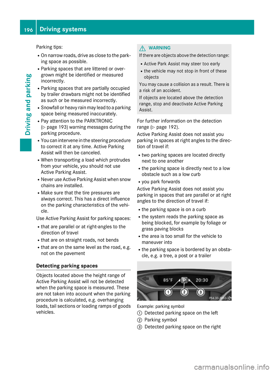
Example: parking symbol
:
Detected parking space on the left
;Parking symbol
=Detected parking space on the right
196Driving systems
Driving and parking
Page 203 of 374
!Objects not at ground level may appear to
be further away than they actually are, e.g.:
Rthe bumper of a parked vehicle
Rthe drawbar of a trailer
Rthe ball coupling of a trailer tow hitch
Rthe rear section of an HGV
Ra slanted post
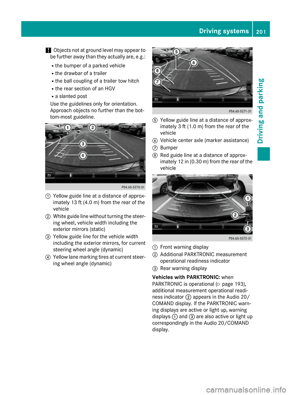
Use the guidelines only for orientation.
Approach objects no further than the bot-
tom-most guideline.
:Yellow guide line at a distance of approx-
imately 13 ft (4.0 m) from the rear of the
vehicle
;White guide line without turning the steer-
ing wheel, vehicle width including the
exterior mirrors (static)
=Yellow guide line for the vehicle width
including the exterior mirrors, for current
steering wheel angle (dynamic)
?Yellow lane marking tires at current steer-
ing wheel angle (dynamic)
AYellow guide line at a distance of approx-
imately 3 ft (1.0 m) from the rear of the
vehicle
BVehicle center axle (marker assistance)
CBumper
DRed guide line at a distance of approx-
imately 12 in (0.30 m) from the rear of the
vehicle
:Front warning display
;Additional PARKTRONIC measurement
operational readiness indicator
=Rear warning display
Vehicles with PARKTRONIC: when
PARKTRONIC is operational (
Ypage 193),
additional measurement operational readi-
ness indicator ;appears in the Audio 20/
COMAND display. If the PARKTRONIC warn-
ing displays are active or light up, warning
displays :and =are also active or light up
correspondingly in the Audio 20/COMAND
display.
Driving systems201
Driving and parking
Z
Page 323 of 374
XStart the engine of the donor vehicle and run it at idling speed.
XConnect negative terminal?of donor battery Bto ground point Aof your vehicle using
the jumper cable, connecting the jumper cable to battery of other vehicle Bfirst.
XIf the battery is fully discharged, leave the battery that is being used to jump-start connected
for a few minutes before attempting to start. This charges the battery slightly.
XStart the engine.
XBefore disconnecting the jumper cables, let the engine run for several minutes.
XFirst, remove the jumper cables from ground point Aand negative terminal ?, then from
positive clamp ;and positive terminal =. Begin each time at the contacts on your own
vehicle first.
XClose cover :of positive terminal ;after removing the jumper cables.
XClose the hood.
XHave the battery checked at a qualified specialist workshop.
iJump-starting is not considered to be a normal operating condition.
iJumper cables and further information regarding jump-starting can be obtained at any
qualified specialist workshop.
Towing and tow-starting
Important safety notes
GWARNING
Functions relevant to safety are restricted or
no longer available if:
Rthe engine is not running.
Rthe brake system or the power steering is
malfunctioning.
Rthere is a malfunction in the voltage supply or the vehicle's electrical system.
If your vehicle is being towed, much more
force may be necessary to steer or brake.
There is a risk of an accident.
In such cases, use a tow bar. Before towing,
make sure that the steering moves freely.
GWARNING
You can no longer steer the vehicle if the
steering wheel lock has been engaged. There
is a risk of an accident.
Always switch off the ignition when towing the
vehicle with a tow cable or a tow bar.
GWARNING
When towing or tow-starting another vehicle
and its weight is greater than the permissible
gross weight of your vehicle, the:
Rthe towing eye could detach itself
Rthe vehicle/trailer combination could roll-
over.
There is a risk of an accident.
When towing or tow-starting another vehicle,
its weight should not be greater than the per- missible gross weight of your vehicle.
Details on the permissible gross vehicle
weight of your vehicle can be found on the
vehicle identification plate (
Ypage 364).
!When COLLISION PREVENTION ASSIST
PLUS, DISTRONIC PLUS or the HOLD func-
tion is activated, the vehicle brakes auto-
matically in certain situations. To avoid
damage to the vehicle, deactivate these
systems in the following or similar situa-
tions:
Rwhen towing the vehicle
Rin the car wash
Towing and tow-starting321
Breakdown assistance
Z
Page 326 of 374
XDepress and hold the brake pedal.
XShift the automatic transmission to posi-
tionN.
XLeave the SmartKey in position 2in the
ignition lock.
XRelease the brake pedal.
XRelease the electric parking brake.
XSwitch on the hazard warning lamps
(
Ypage 117).
iIn order to signal a change of direction
when towing the vehicle with the hazard
warning lamps switched on, use the com-
bination switch as usual. In this case, only
the indicator lamps for the direction of
travel flash. After resetting the combina-
tion switch, the hazard warning lamp starts
flashing again.
Transporting the vehicle
4MATIC vehicles/vehicles with auto-
matic transmission
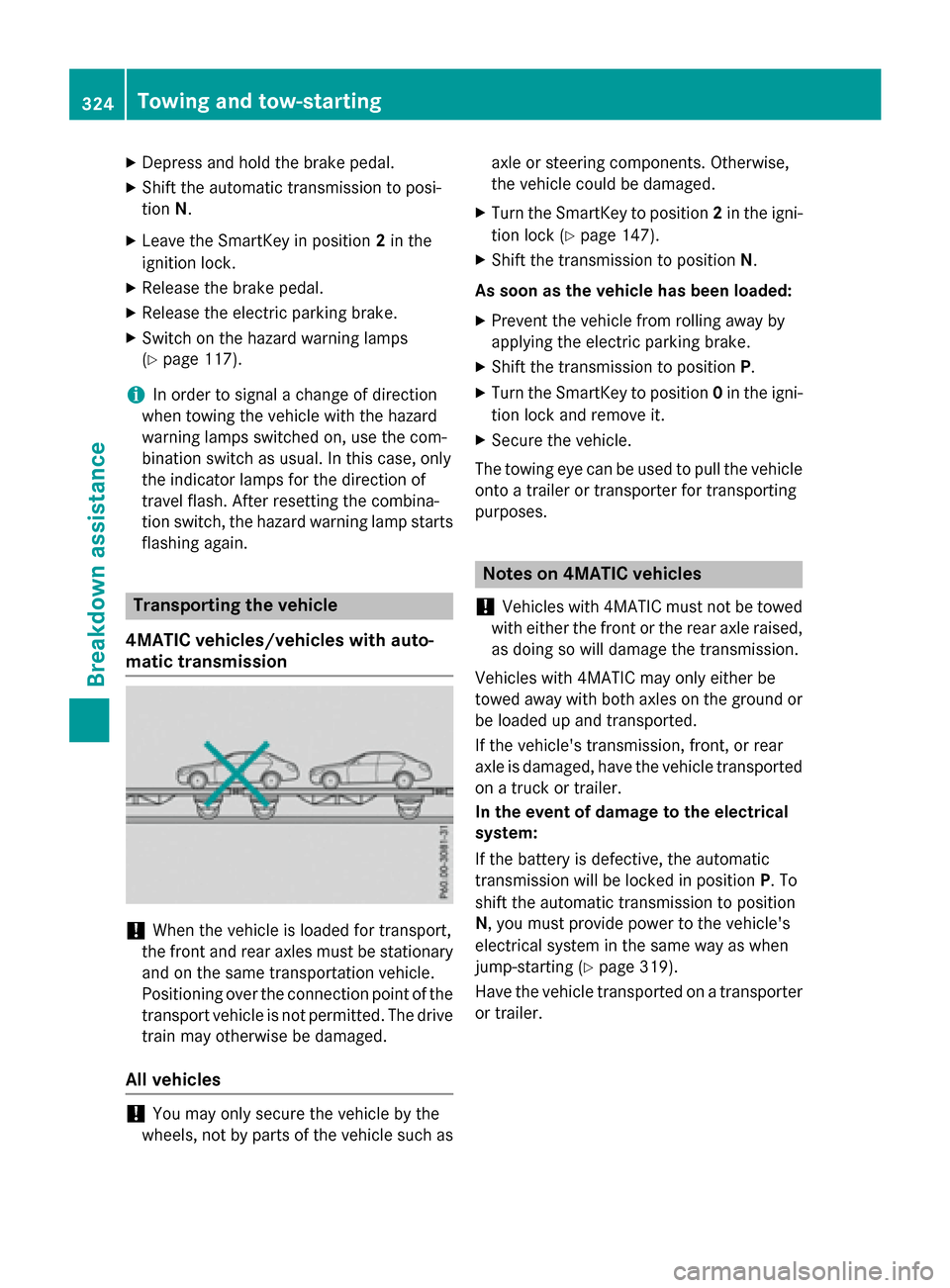
!When the vehicle is loaded for transport,
the front and rear axles must be stationary
and on the same transportation vehicle.
Positioning over the connection point of the
transport vehicle is not permitted. The drive
train may otherwise be damaged.
All vehicles
!You may only secure the vehicle by the
wheels, not by parts of the vehicle such as axle or steering components. Otherwise,
the vehicle could be damaged.
XTurn the SmartKey to position
2in the igni-
tion lock (
Ypage 147).
XShift the transmission to position N.
As soon as the vehicle has been loaded:
XPrevent the vehicle from rolling away by
applying the electric parking brake.
XShift the transmission to position P.
XTurn the SmartKey to position 0in the igni-
tion lock and remove it.
XSecure the vehicle.
The towing eye can be used to pull the vehicle
onto a trailer or transporter for transporting
purposes.
Notes on 4MATIC vehicles
!
Vehicles with 4MATIC must not be towed
with either the front or the rear axle raised,
as doing so will damage the transmission.
Vehicles with 4MATIC may only either be
towed away with both axles on the ground or
be loaded up and transported.
If the vehicle's transmission, front, or rear
axle is damaged, have the vehicle transported
on a truck or trailer.
In the event of damage to the electrical
system:
If the battery is defective, the automatic
transmission will be locked in position P. To
shift the automatic transmission to position
N, you must provide power to the vehicle's
electrical system in the same way as when
jump-starting (
Ypage 319).
Have the vehicle transported on a transporter
or trailer.
324Towing and tow-starting
Breakdown assistance
Page 345 of 374
Step 3
Example 1Example 2Example 3
Permissible load
(maximum gross vehi-
cle weight rating from
the Tire and Loading
Information placard
minus the gross
weight of all occu-
pants)1500 lbs (680 kg)Ò
750 lbs (340 kg) =
750 lbs (340 kg)1500 lbs (680 kg) Ò
540 lbs (245 kg)
=960 lbs (435 kg)1500 lbs (680 kg) Ò
150 lbs (68 kg) =
1350 lbs (612 kg)
Vehicle identification plate
Even if you have calculated the total cargo
carefully, you should still make sure that the
gross vehicle weight rating and the gross axle
weight rating are not exceeded. Details can
be found on the vehicle identification plate on
the B-pillar on the driver's side of the vehicle
(
Ypage 339).
Permissible Gross Vehicle Weight Rating
(GVWR): the gross weight of the vehicle, all
passengers, load and trailer load/noseweight
(if applicable) must not exceed the permissi-
ble gross vehicle weight.
Gross Axle Weight Rating (GAWR): the
maximum permissible weight that can be car-
ried by one axle (front or rear axle).
To ensure that your vehicle does not exceed
the maximum permissible values (gross vehi-
cle weight and maximum gross axle weight
rating), have your loaded vehicle (including
driver, occupants, cargo, and full trailer load if
applicable) weighed on a suitable vehicle
weighbridge.
All about wheels and tires
Uniform Tire Quality Grading Stand-
ards
Overview of Tire Quality Grading Stand-
ards
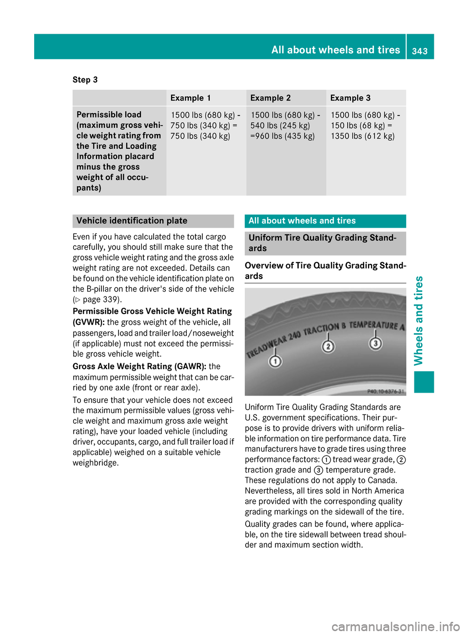
Uniform Tire Quality Grading Standards are
U.S. government specifications. Their pur-
pose is to provide drivers with uniform relia-
ble information on tire performance data. Tire
manufacturers have to grade tires using three
performance factors: :tread wear grade, ;
traction grade and =temperature grade.
These regulations do not apply to Canada.
Nevertheless, all tires sold in North America
are provided with the corresponding quality
grading markings on the sidewall of the tire.
Quality grades can be found, where applica-
ble, on the tire sidewall between tread shoul-
der and maximum section width.
All about wheels and tires343
Wheels and tires
Z