coolant temperature MERCEDES-BENZ CLA COUPE 2013 Owners Manual
[x] Cancel search | Manufacturer: MERCEDES-BENZ, Model Year: 2013, Model line: CLA COUPE, Model: MERCEDES-BENZ CLA COUPE 2013Pages: 373, PDF Size: 11.47 MB
Page 10 of 373
Cornering light function ................
.120
Dipped-beam headlamps .............. .119
Main-beam headlamps ................... 119
Rear foglamp ................................. 120
Reversing lamps ............................ 120
Turn signals (front) ......................... 120
Turn signals (rear) .......................... 120
Child seat
Automatic recognition ..................... 53
ISOFIX .............................................. 54
On the front-passenger sea t............ 52
Problem (malfunction) ..................... 62
Recommendations ........................... 59
Suitable positions ............................ 57
Top Tether ....................................... 55
Child-proof locks
Important safety notes .................... 62
Rear doors ....................................... 63
Children
In the vehicle ................................... 51
Restraint systems ............................ 51
Cigarette lighter ................................ 284
Cleaning
Trailer tow hitch ............................. 301
Climate control
Auxiliary heating/ventilation .......... 138
Controlling automaticall y............... 132
Convenience opening/closing
(air-recirculation mode) ................. 136
Cooling with air dehumidification .. 130
Demisting the windows .................. 134
Demisting the windscreen ............. 134
Important safety notes .................. 126
Indicator lamp ................................ 132
Notes on using THERMATIC auto-
matic climate control ..................... 127
Notes on using THERMOTRONIC
automatic climate control .............. 129
Overview of systems ...................... 126
Problem with the rear window
heating .......................................... 136
Problems with cooling with air
dehumidification ............................ 132
Setting the air distribution ............. 133
Setting the air vents ...................... 143
Setting the airflow ......................... 133
Setting the temperature ................ 132 Switching air-recirculation mode
on/of
f............................................ 136
Switching on/of f........................... 130
Switching residual heat on/off ...... 137
Switching the rear window heat-
ing on/of f...................................... 135
Switching the ZONE function on/
off .................................................. 133
THERMATIC automatic climate
control ........................................... 127
THERMOTRONIC (2-zone) auto-
matic climate control ..................... 129
Cockpit
Overview .......................................... 28
see Instrument cluster
COLLISION PREVENTION ASSIST
Activating/deactivating the dis-
tance warning function .................. 224
Display message ............................ 235
Operation/note s.............................. 65
COLLISION PREVENTION ASSIST
PLUS
Activating/deactivating ................. 224
Display message ............................ 242
Operation/note s.............................. 67
COMAND Online
see separate operating instructions
Combination switch .......................... 113
Consumption statistics (on-board
computer) .......................................... 217
Convenience closing feature .............. 90
Convenience opening feature ............ 90
Convenience opening/closing (air-
recirculation mode) ........................... 136
Coolant (engine)
Checking the level ......................... 294
Display message ............................ 249
Important safety notes .................. 360
Temperature (on-board com-
puter) ............................................. 231
Temperature gaug e........................ 214
Warning lamp ................................. 271
Cooling
see Climate control
Copyright ............................................. 26
Cornering lamps
Changing bulb s.............................. 120 Index
7
Page 21 of 373
Stowage well beneath the boot
floor
....................................................2 81
Summer tyres ................................... .328
Sun visor ............................................ 283
Supplemental restraint system
see SRS (Supplemental Restraint
System)
Surround lighting (on-board com-
puter) ................................................. .228 T
Tail lamps Display message ............................ 246
see Lights
Tank
see Fuel tank
Technical data
Emergency spare wheel ................. 350
Information ................................... .352
Trailer loads ................................... 364
Tyres/wheels ................................. 340
Vehicle data ................................... 362
Telephone
Accepting a call ............................ .222
Display message ............................ 262
Menu (on-board computer) ............ 221
Number from the phone book ....... .222
Redialling ....................................... 222
Rejecting/ending a call ................. 222
Telephone compartment ................ 278
Temperature
Coolant .......................................... 214
Coolant (on-board computer) ......... 231
Engine oil (on-board computer) ...... 231
Outside temperature ..................... .215
Setting (climate control) ................ 132
TEMPOMAT
Function/notes ............................ .173
Theft-deterrent system
ATA (Anti-Theft Alarm system) ......... 73
Immobiliser ...................................... 72
Through-loading ................................ 279
Through-loading feature ................... 279
Time
see Separate Owner's manual
Timing (RACETIMER) ......................... 232
TIREFIT kit .......................................... 309 Top Tether
............................................ 55
Tow-away protection
Activating ......................................... 73
Deactivating ..................................... 73
Function .......................................... .73
Tow-starting
Emergency engine starting ............ 322
Fitting the towing ey e.................... 320
Important safety notes .................. 318
Removing the towing eye ............... 320
Towing
Important safety notes .................. 318
Notes for 4MATIC vehicles ............ 321
Towing a trailer
Active Parking Assist ..................... 197
Axle load, permissibl e.................... 364
Bulb failure indicator for LED
lamps ............................................. 212
ESP® (Electronic Stability Pro-
gram) ............................................... 71
Pulling away with a traile r.............. 149
Trailer tow hitch display message .. 261
Towing away
Fitting the towing ey e.................... 320
Removing the towing eye ............... 320
With both axles on the ground ....... 321
With front axle raised ..................... 320
Trailer coupling
see Towing a trailer
Trailer towing
7-pin connecto r............................. 212
Blind Spot Assist ............................ 205
Cleaning the trailer tow hitch ......... 301
Coupling up a traile r...................... 210
Decoupling a trailer ....................... 210
Driving tip s.................................... 207
Folding in the ball coupling ............ 211
Folding out the ball coupling .......... 209
Important safety notes .................. 207
Lights display message .................. 245
Mounting dimensions .................... 363
Parktroni c...................................... 191
Power supply ................................. 211
Trailer load s................................... 364
Transmission
see Automatic transmission
see Manual transmission 18
Index
Page 33 of 373
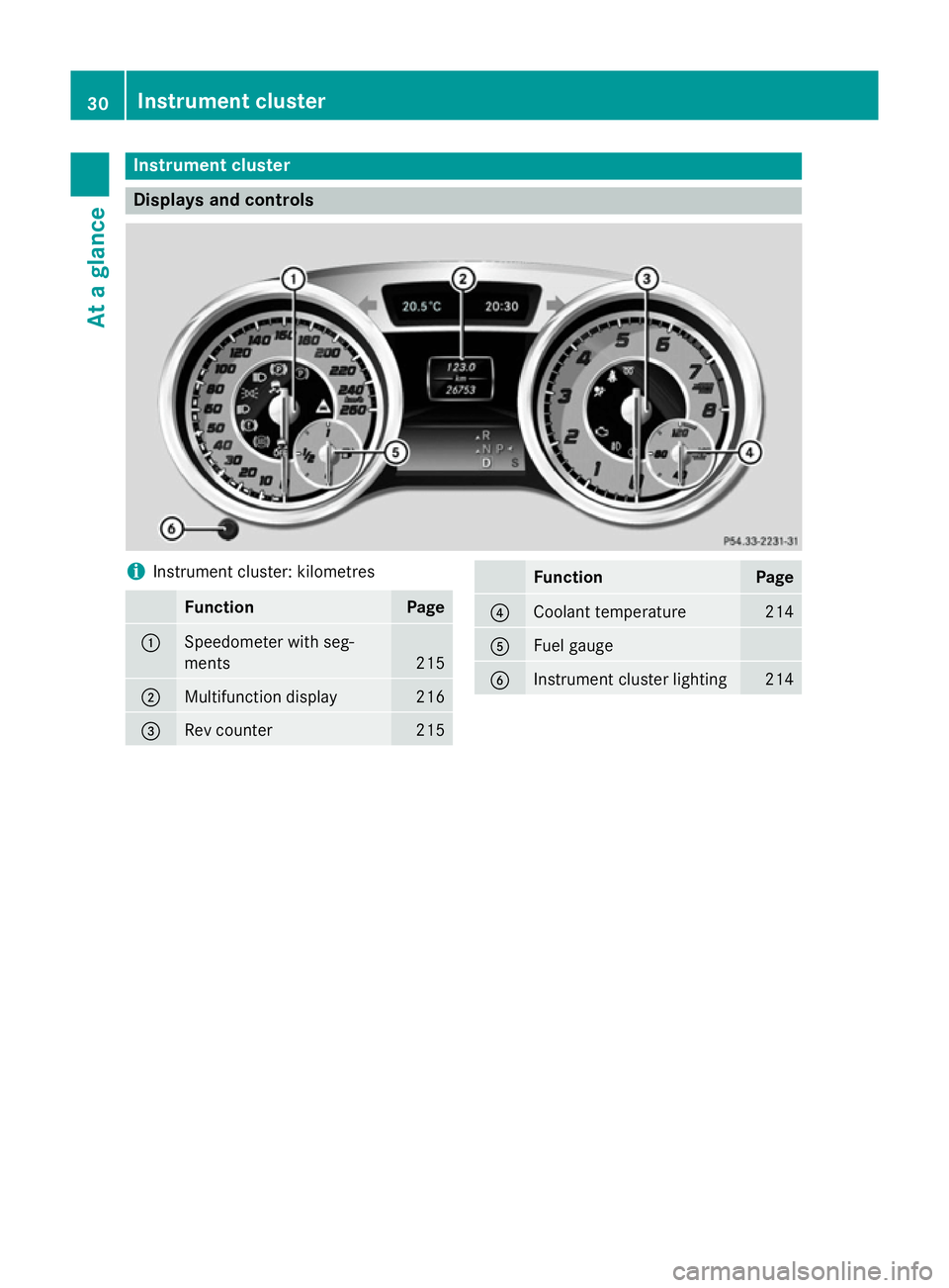
Instrument cluster
Displays and controls
i
Instrument cluster: kilometres Function Page
:
Speedometer with seg-
ments
215
;
Multifunction display 216
=
Rev counter 215 Function Page
?
Coolant temperature 214
A
Fuel gauge
B
Instrument cluster lighting 21430
Instrument clusterAt a glance
Page 34 of 373
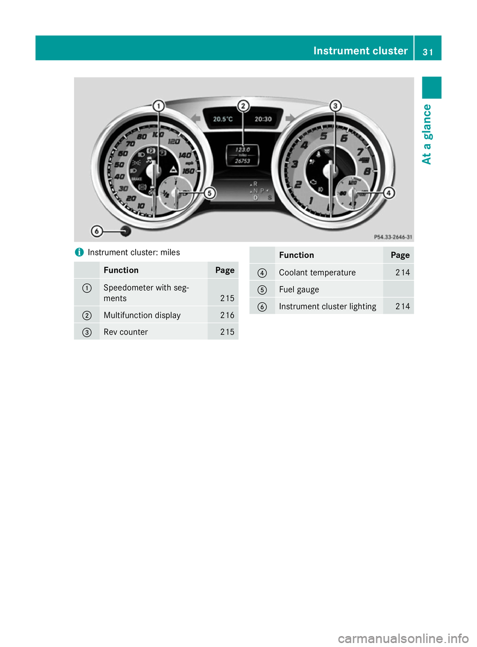
i
Instrument cluster: miles Function Page
:
Speedometer with seg-
ments 215
;
Multifunction display 216
=
Rev counter 215 Function Page
?
Coolant temperature 214
A
Fuel gauge
B
Instrument cluster lighting 214Instrument cluster
31At a glance
Page 157 of 373
Problem
Possible causes/consequences and
M
MSolutions Vehicles with a petrol
engine:
the engine is not run-
ning smoothly and is
misfiring. There is a malfunction in the engine electronics or in a mechanical
component of the engine management system.
X Only depress the accelerator pedal slightly.
Otherwise, non-combusted fuel may get into the catalytic con-
verter and damage it.
X Have the cause rectified immediately at a qualified specialist
workshop. The coolant tempera-
ture display is showing
more than 120 †. The
coolant warning lamp
may also be on and a
warning tone may
sound. The coolant level is too low. The coolant is too hot and the engine
is no longer being cooled sufficiently.
X Stop as soon as possible and allow the engine and the coolant to
cool down.
X Check the coolant level (Y page 294). Observe the warning
notes as you do so and top up the coolant if necessary. If the coolant level is correct, the engine radiator fan may be faulty.
The coolant is too hot and the engine is no longer being cooled
sufficiently.
X If the coolant temperature is below 120 †, you can continue
driving to the nearest qualified specialist workshop.
X Avoid heavy loads on the engine as you do so, e.g. driving in
mountainous terrain and stop-start traffic. Manual transmission
Gear lever
! Only engage gear when the clutch pedal is
depressed.
! When shifting to
5thand 6thgear, you
must press the shift lever to the right. Oth- erwise, you could shift unintentionally into
3rd or4th gear and damage the engine or
transmission.
If you shift down at too high a speed (trans-
mission braking), this can cause the engine
to overrev, leading to engine damage.
Do not use the clutch bite point to keep the vehicle stationary on uphill gradients.
There is otherwise a risk of damaging the
clutch.
! On long and steep downhill gradients,
especially if the vehicle is laden or towing a trailer, you must shift into gear
1, 2or3in
good time. This uses the engine's braking
effect. This relieves the load on the brake
system and prevents the brakes from over-
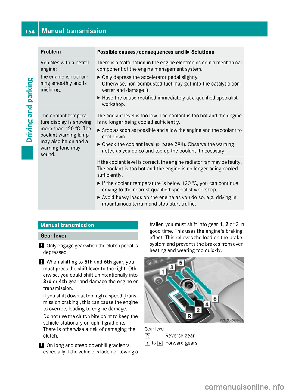
heating and wearing too quickly. Gear lever
k
Reverse gear
1 to6
Forward gears 154
Manual transmissionDriving and parking
Page 217 of 373
Useful information
i This Owner's Manual describes all mod-
els, series and optional equipment for your
vehicle that were available at the time of
going to press. National variations are pos- sible. Note that your vehicle may not be
equipped with all of the functions descri-
bed. This is also the case for systems and
functions relevant to safety.
i Read the information on qualified special-
ist workshops: (Y page 24). Important safety notes
G
WARNING
Operating the integrated information systems and communications equipment in the vehicle
while driving will distract you from traffic con-
ditions. You could then lose control of the
vehicle. There is a risk of an accident.
Only operate these devices if road traffic con-
ditions permit. If you are unsure about the
surrounding conditions, pull over to a safe
location and make entries only while the vehi-
cle is stationary. G
WARNING
If the instrument cluster has failed or mal-
functioned, you may not recognise function
restrictions relevant to safety. The operating
safety of your vehicle may be impaired. There is a risk of an accident.
Drive on carefully. Have the vehicle checked
at a qualified specialist workshop immedi-
ately.
You must observe the legal requirements for
the country in which you are currently driving when operating the on-board computer.
The on-board computer only shows messages
or warnings from certain systems in the mul- tifunction display. You should therefore make
sure your vehicle is operating safely at all times. Otherwise, a vehicle that is not oper-
ating safely may cause an accident.
For an overview, see the instrument panel
illustration (Y
page 30). Displays and operation
Instrument cluster lighting
The lighting in the instrument cluster, in the
displays and the controls in the vehicle inte-
rior can be adjusted using the brightness con- trol knob.
The brightness control knob is on the bottom
left of the instrument cluster (Y page 30).
X Turn the brightness control knob clockwise
or anti-clockwise.
If the light switch is set to Ã,Tor
L, the brightness is dependant upon
the brightness of the ambient light.
i The light sensor in the instrument cluster
automatically controls the brightness of
the multifunction display.
In daylight, the displays in the instrument
cluster are not illuminated. Coolant temperature gauge
G
WARNING
If you open the bonnet while the engine is
overheating or while there is a fire in the
engine compartment, you could come into
contact with hot gases or other leaking ser-
vice products. There is a danger of injury.
Allow an overheating engine to cool down
before opening the bonnet. If there is a fire in the engine compartment, leave the bonnet
closed and notify the fire brigade.
The coolant temperature gauge is in the
instrument cluster on the right-hand side.
Under normal operating conditions and with
the specified coolant level, the coolant tem-
perature may rise to 120 †. 214
Displays and operationOn-board computer and displays
Page 218 of 373
At high outside temperatures and when driv-
ing uphill, the coolant temperature may rise
to the end of the scale. Rev counter
! Do not drive in the overrevving range.
Doing so will damage the engine.
The red band in the rev counter indicates the
engine's overrevving range.
The fuel supply is interrupted to protect the
engine when the red band is reached. Outside temperature display
You should pay special attention to road con-
ditions when temperatures are around the
freezing point.
The outside temperature display is in the mul- tifunction display.
Changes in the outside temperature are dis-
played after a short delay. Speedometer with segments
The speedometer is divided into segments on
vehicles with DISTRONIC PLUS.
The segments in the speedometer indicate
which speed range is available.
R Cruise control activated (Y page 173):
The segments light up from the stored
speed to the maximum speed.
R Variable SPEEDTRONIC activated
(Y page 176):
The segments light up from the start of the
scale to the selected limit speed.
R DISTRONIC PLUS activated (Y page 178):
One or two segments in the set speed
range light up.
R DISTRONIC PLUS detects a vehicle in front:
The segments between the speed of the
vehicle in front and the stored speed light
up. Operating the on-board computer
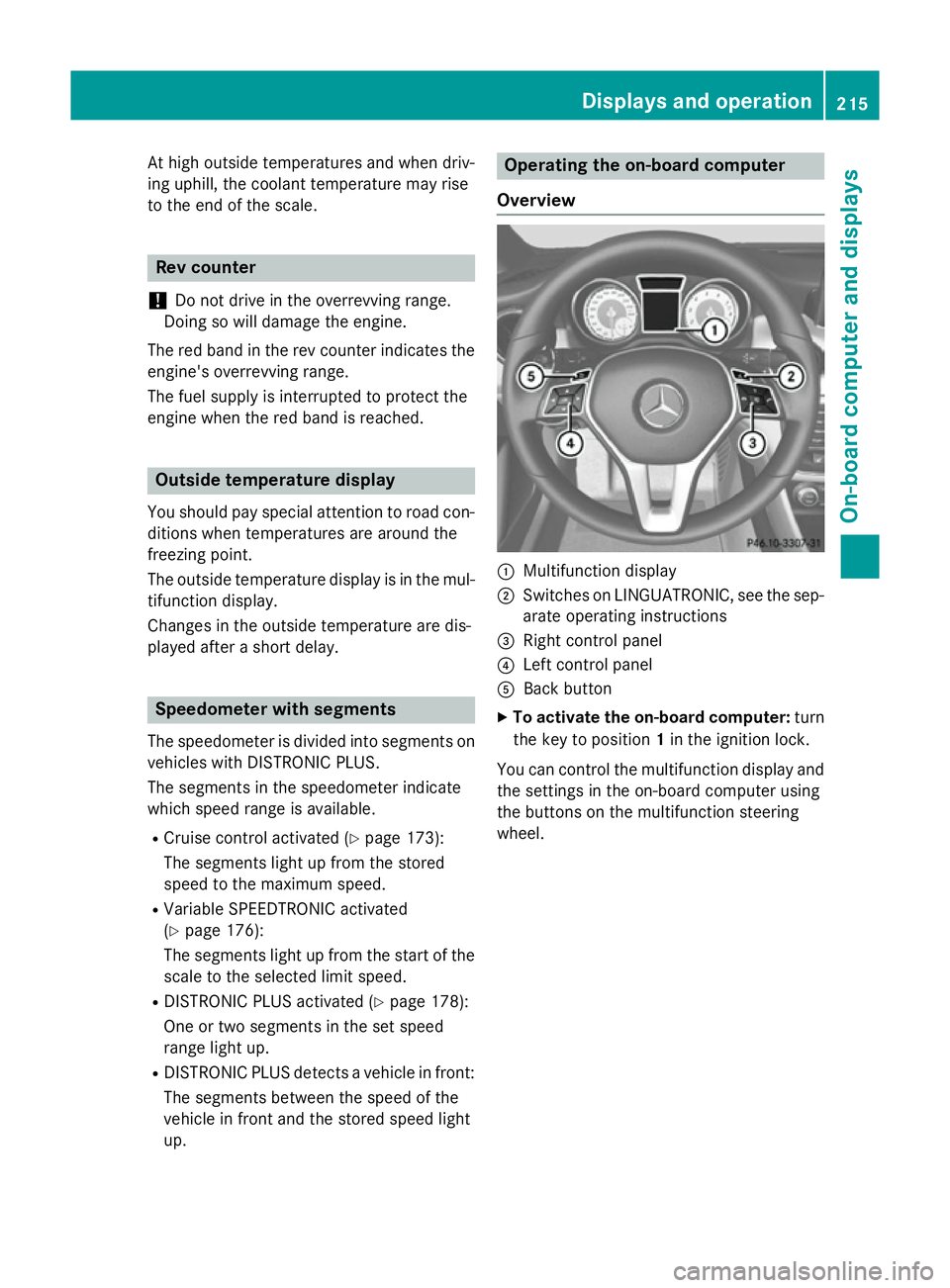
Overview :
Multifunction display
; Switches on LINGUATRONIC, see the sep-
arate operating instructions
= Right control panel
? Left control panel
A Back button
X To activate the on-board computer: turn
the key to position 1in the ignition lock.
You can control the multifunction display and
the settings in the on-board computer using
the buttons on the multifunction steering
wheel. Displays and operation
215On-board computer and displays Z
Page 234 of 373
X
Press the =or; button on the steer-
ing wheel to select the Settings Settingsmenu.
X Press the :or9 button to select the
Convenience
Convenience submenu.
X Press ato confirm.
X Press the :or9 button to select the
Auto. fold-in mirrors
Auto. fold-in mirrors function.
If the Auto. Auto. fold-in
fold-in mirrors
mirrorsfunction is
activated, the vehicle's exterior mirror is
displayed in orange in the multifunction
display.
X Press the abutton to save the setting.
Resetting to factory settings X
Press the =or; button on the steer-
ing wheel to select the Settings Settingsmenu.
X Press the :or9 button to select the
Factory setting
Factory setting submenu.
X Press ato confirm.
The Reset all settings?
Reset all settings? message
appears.
X Press the :or9 button to select No
No
or Yes
Yes.
X Press the abutton to confirm the selec-
tion.
If you have selected Yes Yes, the multifunction
display shows a confirmation message.
For safety reasons, not all functions are reset: the Limit
Limit speed
speed(winter
(winter tyres)
tyres)function
in permanent SPEEDTRONIC can only be set
in the Vehicle
Vehicle submenu. If you want to reset
the Daytime
Daytime driving
drivinglights
lightsin theLights
Lights
submenu, you must turn the key to position 1
in the ignition lock. AMG menu in AMG vehicles
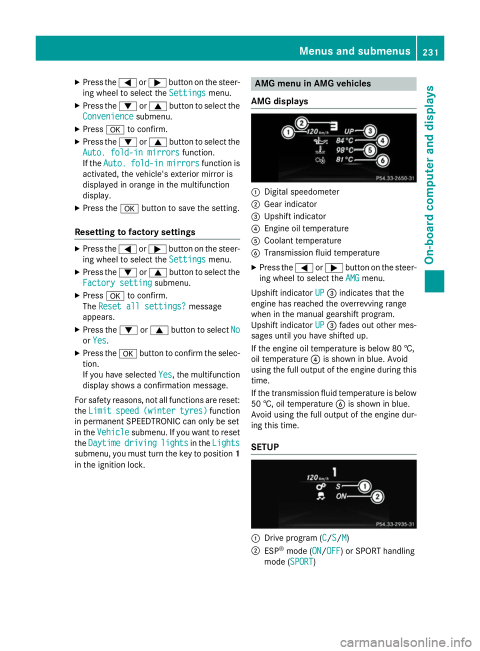
AMG displays :
Digital speedometer
; Gear indicator
= Upshift indicator
? Engine oil temperature
A Coolant temperature
B Transmission fluid temperature
X Press the =or; button on the steer-
ing wheel to select the AMG
AMGmenu.
Upshift indicator UP
UP= indicates that the
engine has reached the overrevving range
when in the manual gearshift program.
Upshift indicator UP UP= fades out other mes-
sages until you have shifted up.
If the engine oil temperature is below 80 †,
oil temperature ?is shown in blue. Avoid
using the full output of the engine during this time.
If the transmission fluid temperature is below
50 †, oil temperature Bis shown in blue.
Avoid using the full output of the engine dur-
ing this time.
SETUP :
Drive program (C C/SS/MM)
; ESP ®
mode (ON ON/OFFOFF) or SPORT handling
mode (SPORT SPORT) Menus and submenus
231On-board computer and displays Z
Page 252 of 373
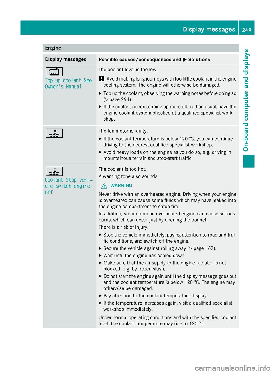
Engine
Display messages
Possible causes/consequences and
M
MSolutions +
Top Top
up
upcoolant
coolant See
See
Owner's Manual
Owner's Manual The coolant level is too low.
! Avoid making long journeys with too little coolant in the engine
cooling system. The engine will otherwise be damaged.
X Top up the coolant, observing the warning notes before doing so
(Y page 294).
X If the coolant needs topping up more often than usual, have the
engine coolant system checked at a qualified specialist work-
shop. ? The fan motor is faulty.
X If the coolant temperature is below 120 †, you can continue
driving to the nearest qualified specialist workshop.
X Avoid heavy loads on the engine as you do so, e.g. driving in
mountainous terrain and stop-start traffic. ?
Coolant Stop vehi‐ Coolant Stop vehi‐
cle Switch engine cle Switch engine
off off The coolant is too hot.
A warning tone also sounds.
G WARNING
Never drive with an overheated engine. Driving when your engine is overheated can cause some fluids which may have leaked into
the engine compartment to catch fire.
In addition, steam from an overheated engine can cause serious
burns, which can occur just by opening the bonnet.
There is a risk of injury.
X Stop the vehicle immediately, paying attention to road and traf-
fic conditions, and switch off the engine.
X Secure the vehicle against rolling away (Y page 167).
X Wait until the engine has cooled down.
X Make sure that the air supply to the engine radiator is not
blocked, e.g. by frozen slush.
X Do not start the engine again until the display message goes out
and the coolant temperature is below 120 †. The engine may
otherwise be damaged.
X Pay attention to the coolant temperature display.
X If the temperature increases again, visit a qualified specialist
workshop immediately.
Under normal operating conditions and with the specified coolant level, the coolant temperature may rise to 120 †. Display messages
249On-board computer and displays Z
Page 274 of 373
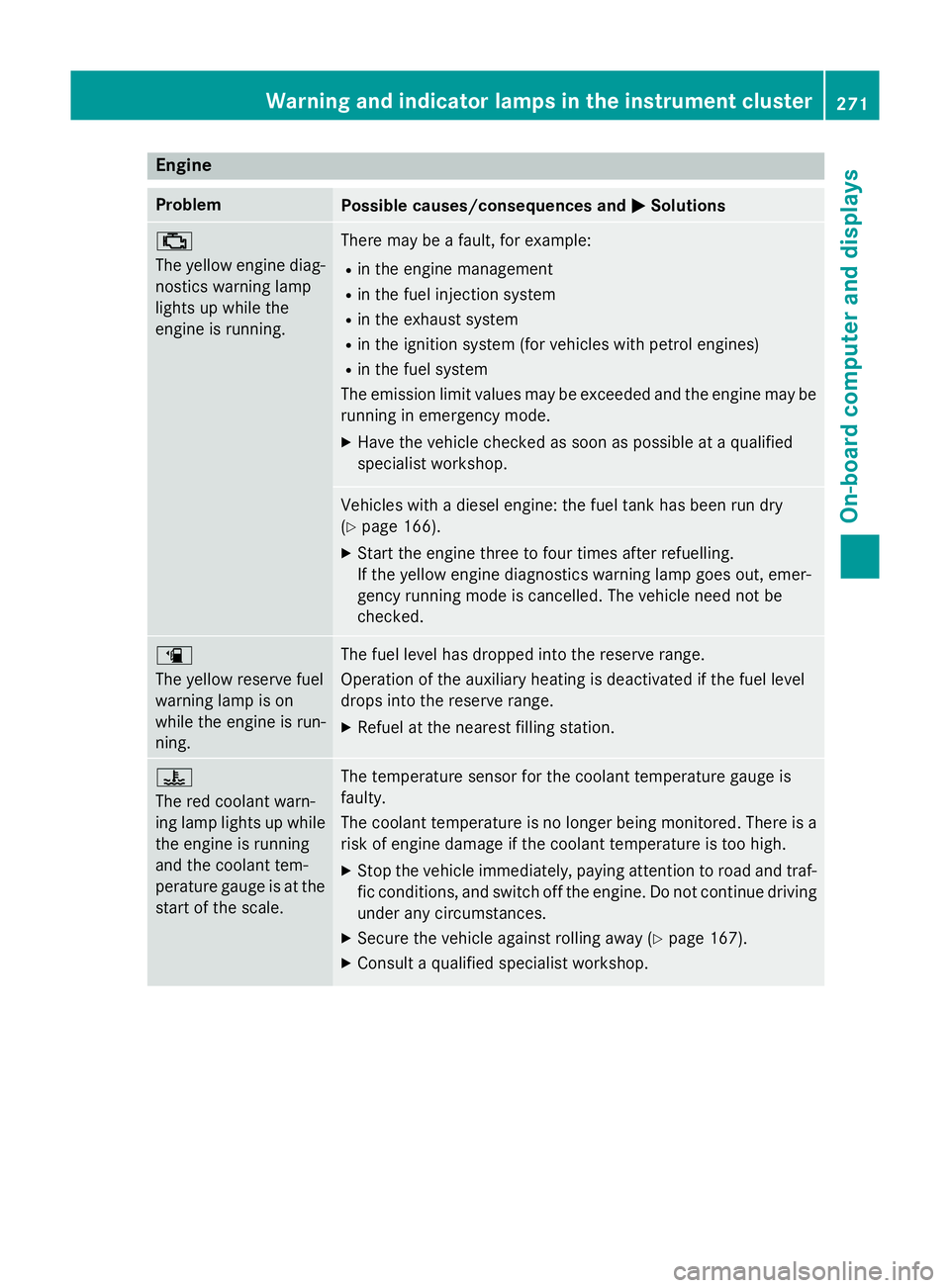
Engine
Problem
Possible causes/consequences and
M
MSolutions ;
The yellow engine diag-
nostics warning lamp
lights up while the
engine is running. There may be a fault, for example:
R in the engine management
R in the fuel injection system
R in the exhaust system
R in the ignition system (for vehicles with petrol engines)
R in the fuel system
The emission limit values may be exceeded and the engine may be running in emergency mode.
X Have the vehicle checked as soon as possible at a qualified
specialist workshop. Vehicles with a diesel engine: the fuel tank has been run dry
(Y
page 166).
X Start the engine three to four times after refuelling.
If the yellow engine diagnostics warning lamp goes out, emer-
gency running mode is cancelled. The vehicle need not be
checked. æ
The yellow reserve fuel
warning lamp is on
while the engine is run-
ning.
The fuel level has dropped into the reserve range.
Operation of the auxiliary heating is deactivated if the fuel level
drops into the reserve range.
X Refuel at the nearest filling station. ?
The red coolant warn-
ing lamp lights up while
the engine is running
and the coolant tem-
perature gauge is at the start of the scale. The temperature sensor for the coolant temperature gauge is
faulty.
The coolant temperature is no longer being monitored. There is a risk of engine damage if the coolant temperature is too high.
X Stop the vehicle immediately, paying attention to road and traf-
fic conditions, and switch off the engine. Do not continue driving
under any circumstances.
X Secure the vehicle against rolling away (Y page 167).
X Consult a qualified specialist workshop. Warning and indicator lamps in the instrument cluster
271On-board computer and displays Z