service indicator MERCEDES-BENZ CLA COUPE 2016 Owners Manual
[x] Cancel search | Manufacturer: MERCEDES-BENZ, Model Year: 2016, Model line: CLA COUPE, Model: MERCEDES-BENZ CLA COUPE 2016Pages: 345, PDF Size: 12.41 MB
Page 18 of 345
Automatic front-passenger front
airbag deactivation .......................... 47
Automatic measures after an acci-
dent ................................................. 53
Children in the vehicle ..................... 54
Important safety note s.................... 39
PASSENGER AIRBAG indicator
lamp ................................................. 40
Pets in the vehicle ........................... 65
PRE-SAFE ®
(anticipatory occu-
pant protection) ............................... 53
Restraint system introduction .......... 39
Restraint system warning lamp ........ 40
Seat belts ........................................ 41
Odometer ........................................... 203
On-board computer
AMG menu ..................................... 213
Assistance graphic menu ............... 208
Assistance menu ........................... 208
Audio menu ................................... 206
Convenience submenu .................. 212
Display messages .......................... 216
Displaying a service message ........ 285
Factory settings ............................. 213
Heating submenu ........................... 211
Important safety notes .................. 200
Instrument cluster submenu .......... 210
Light submenu ............................... 211
Menu overview .............................. 203
Message memory .......................... 216
Navigation menu ............................ 205
Operating video DVD ..................... 206
Operation ....................................... 201
RACETIMER ................................... 214
Service menu ................................. 210
Settings menu ............................... 210
Standard display ............................ 203
Telephone menu ............................ 207
Trip menu ...................................... 203
Vehicle submenu ........................... 211
Opening and closing the side trim
panels ................................................. 113
Operating instructions
Vehicle equipment ........................... 25
Operating safety
Declaration of conformity ................ 26
Important safety note ...................... 25 Operating system
see On-board computer
Operation
Digital Owner's Manua l.................... 23
Outside temperature display ........... 200
Overhead control panel ...................... 38
Override feature
Rear side window s........................... 65 P
Paint code .......................................... 326
Paintwork (cleaning instructions) ... 287
Panic alarm .......................................... 39
Panorama sliding sunroof
Important safety information ........... 92
Operating ......................................... 93
Operating the roller sunblinds for
the sliding sunroof ........................... 94
Problem (malfunction) ..................... 95
Rain-closing feature (when driv-
ing) .................................................. 94
Rain-closing feature (when the
engine is switched off) ..................... 94
Reversing feature ............................. 93
Parking
Important safety notes .................. 155
Parking brake ................................ 157
Parking position for the exterior
mirror on the front-passenger
side ................................................ 105
Reversing camera .......................... 184
Parking aid
see Exterior mirrors
see Reversing camera
Parking Assist PARKTRONIC
Deactivating/activating ................. 179
Driving system ............................... 177
Function/note s............................. 177
Important safety notes .................. 177
Problems (faults) ........................... 180
Sensor rang e................................. 177
Warning display ............................. 178
Parking brake
Applying automatically (vehicles
with automatic transmission) ......... 158
Applying automatically (vehicles
with manual transmission) ............. 158 Index
15
Page 24 of 345
Trim pieces (cleaning instruc-
tions)
.................................................. 291
Trip computer (on-board com-
puter) .................................................. 203
Trip meter
Calling up ....................................... 203
Resetting (on-board computer) ...... 204
Turn signal lamp
Replacing bulbs (rear ).................... 113
Turn signals
Replacing bulbs (front) ................... 113
Switching on/of f........................... 109
Two-way radio
Frequencies ................................... 325
Installation ..................................... 325
Transmission output (maximum) .... 325
Type identification plate
see Vehicle identification plate
Tyre inflation compressor
see TIREFIT kit
Tyre pressure
Calling up (on-board computer) ..... 315
Display message ............................ 239
Not reached (TIREFIT) .................... 297
Reached (TIREFIT) .......................... 298
Recommended ............................... 313
Tyre pressure loss warning
General notes ................................ 314
Important safety notes .................. 315
Restarting ...................................... 315
Tyre pressure monitor
Checking the tyre pressure elec-
tronically ........................................ 316
Function/note s............................. 315
General notes ................................ 315
Important safety notes .................. 316
Radio type approval for the tyre
pressure monitor ........................... 317
Restarting ...................................... 317
Warning lamp ................................. 258
Warning message .......................... 317
Tyres
Changing a whee l.......................... 318
Checking ........................................ 310
Direction of rotation ...................... 319
Display message ............................ 239
General notes ................................ 323
Important safety notes .................. 310 Information on driving .................... 310
M+S tyres ...................................... 312
MOExtended tyre
s......................... 312
Replacing ....................................... 318
Service life ..................................... 311
Storing ........................................... 319
Summer tyres ................................ 312
Tyre size (data ).............................. 323
Tyre tread ...................................... 311
see Flat tyre U
Unlocking Emergency unlocking ....................... 85
From inside the vehicle (central
unlocking button) ............................. 84
Upshift indicator (on-board com-
puter, Mercedes-AMG vehicles) ....... 213
USB devices
Connecting to the Media Inter-
face ............................................... 267 V
Vanity mirror (in sun visor) .............. 275
Vehicle
Correct use ...................................... 28
Data acquisition ............................... 28
Display message ............................ 241
Electronics ..................................... 325
Equipment ....................................... 25
Implied warranty .............................. 28
Individual settings .......................... 210
Leaving parked up ......................... 159
Locking (in an emergency) ............... 85
Locking (key) ................................... 76
Lowering ........................................ 322
Pulling away ................................... 135
Raising ........................................... 320
Registration ..................................... 28
Securing from rolling away ............ 319
Transporting .................................. 307
Unlocking (in an emergency) ........... 85
Unlocking (key) ................................ 76
Vehicle data ................................... 333
Vehicle data
Boot load (maximum) ..................... 333
Roof load (maximum) ..................... 333 Index
21
Page 52 of 345
system manufacturer's installation instruc-
tions.
Always observe the vehicle-specific information for the correct positioning of the child restraint
system (Y page 59).
If the automatic front-passenger front airbag
deactivation system detects that:
R the front-passenger seat is unoccupied, the
PASSENGER AIR BAG OFF indicator lamp
lights up after the system self-test and
remains lit. This indicates that the front-
passenger front airbag is disabled.
R the front-passenger seat is occupied by a
child in a rearward-facing child restraint sys-
tem, the PASSENGER AIR BAG OFF indicator
lamp lights up after the system self-test and
remains lit. This indicates that the front-
passenger front airbag is disabled.
But in the case of a child in a rearward-facing
child restraint system, the PASSENGER AIR
BAG OFF indicator lamp can also go out after
the system self-test. This indicates that the
front-passenger front airbag is enabled. The
result of the classification is dependent on,
among other factors, the child restraint sys-
tem and the child's stature. It is recommen-
ded that you fit the child restraint system to a
suitable rear seat.
R the front-passenger seat is occupied by a
child in a forward-facing child restraint sys-
tem, either the PASSENGER AIR BAG OFF
indicator lamp lights up and remains lit after
the system self-test depending on the result
of the classification, or it goes out. The result of the classification is dependent on, among
other factors, the child restraint system and
the child's stature.
Move the front-passenger seat as far back as
possible. Always observe the information in
"Child restraint systems on the front-
passenger seat" (Y page 57) and in "Suita-
ble positioning of the child restraint system"
(Y page 59). Alternatively, you can fit the
child restraint system to a suitable rear seat.
R the front-passenger seat is occupied by a per-
son of smaller stature (e.g. a teenager or
small adult), the PASSENGER AIR BAG OFF
indicator lamp lights up and remains lit after
the system self-test depending on the result
of the classification or, alternatively, goes out.
- If the PASSENGER AIR BAG OFF indicator
lamp is off, move the front-passenger seat as far back as possible. Alternatively, a per-
son with a small stature can sit on a rear
seat.
- If the PASSENGER AIR BAG OFF indicator
lamp is lit, a person with a smaller stature
should not use the front-passenger seat.
R the front-passenger seat is occupied by an
adult or a person with the stature of an adult,
the PASSENGER AIR BAG OFF indicator lamp
goes out after the system self-test. This indi-
cates that the front-passenger front airbag is enabled.
If children are travelling in the vehicle, be sure to
observe the notes on "Children in the vehicle"
(Y page 54).
If the automatic front-passenger front airbag
deactivation system is malfunctioning, the red
6 restraint system warning lamp on the
instrument cluster and the PASSENGER AIR
BAG OFF indicator lamp light up simultaneously.
The front-passenger front airbag is disabled in
this case and does not deploy during an acci-
dent. Have the automatic front-passenger front airbag deactivation system checked and
repaired immediately at a qualified specialist
workshop. Mercedes-Benz recommends that
you use a Mercedes-Benz Service Centre for this
purpose.
If the front-passenger seat, the seat cover or the seat cushion are damaged, have the necessary
repair work carried out at a qualified specialist
workshop. Mercedes-Benz recommends that
you use a Mercedes-Benz Service Centre for this
purpose.
For safety reasons, Mercedes-Benz recom-
mends that you use only a child restraint system that has been tested and approved by
Mercedes-Benz in combination with the auto-
matic front-passenger front airbag deactivation
system.
System self-test G
DANGER
If both the PASSENGER AIR BAG OFF and
PASSENGER AIR BAG ON indicator lamps do
not light up during the system self-test, the
system is malfunctioning. The front-
passenger front airbag might be triggered
unintentionally or might not be triggered at all in the event of an accident with high deceler- Occupant safety
49Safety
Z
Page 119 of 345
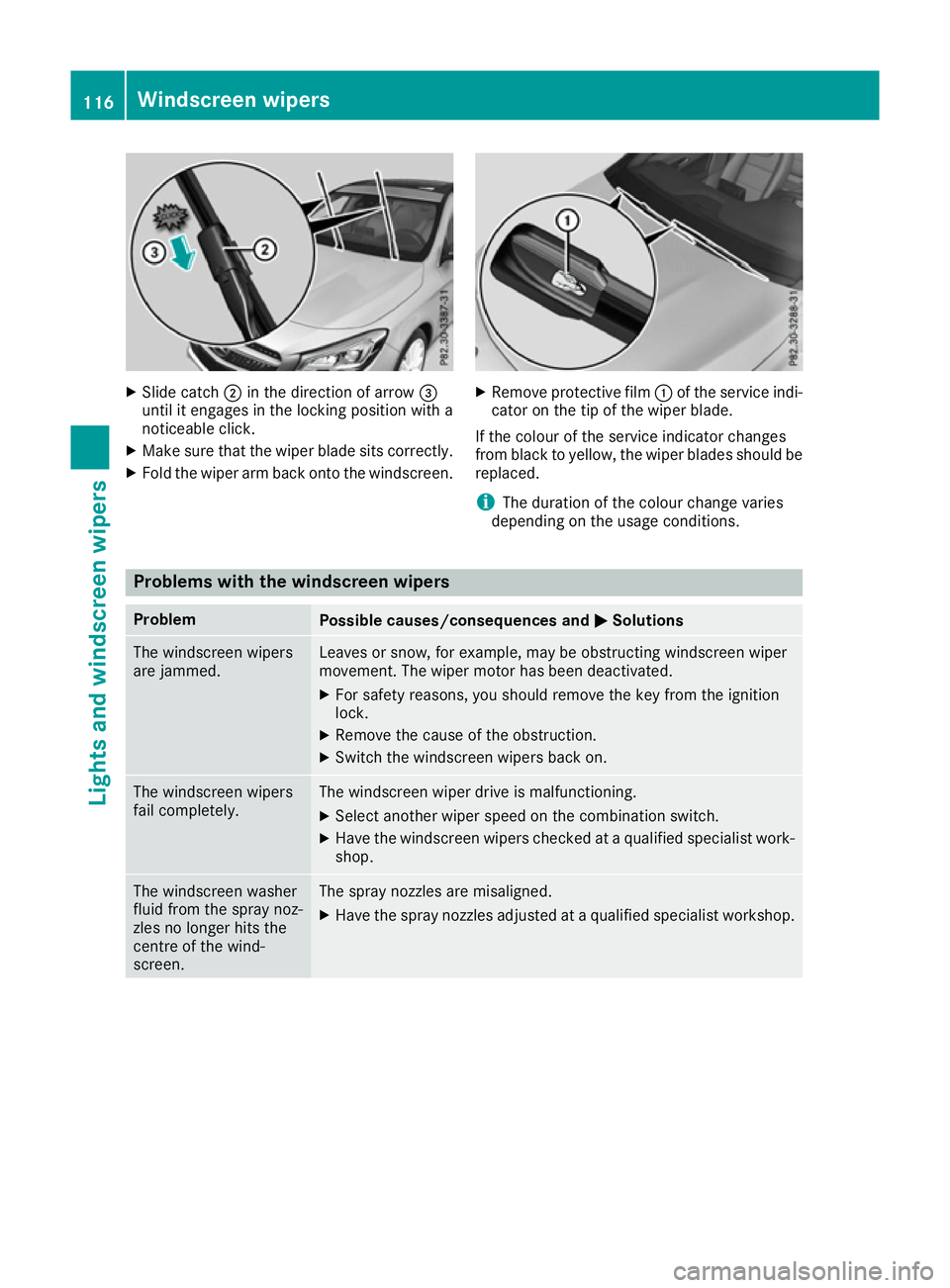
X
Slide catch ;in the direction of arrow =
until it engages in the locking position with a
noticeable click.
X Make sure that the wiper blade sits correctly.
X Fold the wiper arm back onto the windscreen. X
Remove protective film :of the service indi-
cator on the tip of the wiper blade.
If the colour of the service indicator changes
from black to yellow, the wiper blades should be replaced.
i The duration of the colour change varies
depending on the usage conditions. Problems with the windscreen wipers
Problem
Possible causes/consequences and
M MSolutions The windscreen wipers
are jammed. Leaves or snow, for example, may be obstructing windscreen wiper
movement. The wiper motor has been deactivated.
X For safety reasons, you should remove the key from the ignition
lock.
X Remove the cause of the obstruction.
X Switch the windscreen wipers back on. The windscreen wipers
fail completely. The windscreen wiper drive is malfunctioning.
X Select another wiper speed on the combination switch.
X Have the windscreen wipers checked at a qualified specialist work-
shop. The windscreen washer
fluid from the spray noz-
zles no longer hits the
centre of the wind-
screen. The spray nozzles are misaligned.
X Have the spray nozzles adjusted at a qualified specialist workshop. 116
Windscreen wipersLights and windscreen wipers
Page 193 of 345
corresponds to the last selection activated
(standard/sensitive).
Warning on the multifunction display If fatigue or increasing lapses in concentration
are detected, a warning appears in the multi-
function display: ATTENTION ASSIST
ATTENTION ASSIST Take a
Take a
break!
break!
In addition to the message shown on the multi-
function display, you will then hear a warning
tone.
X If necessary, take a break.
X Confirm the message by pressing the a
button on the steering wheel.
On long journeys, take regular breaks that allow
for adequate recuperation. If you do not take a
break and ATTENTION ASSIST still detects
increasing lapses in concentration, you will be
warned again after 15 minutes at the earliest.
This will happen only if ATTENTION ASSIST still
detects typical indicators of fatigue or increas-
ing lapses in concentration.
Vehicles with multimedia system COMAND
Online: if a warning is output in the multifunc-
tion display, a service station search is per-
formed in the multimedia system. You can
select a service station and you will then be
navigated to this service station. This function
can be activated and deactivated in the multi-
media system; see Digital Owner's Manual. Traffic Sign Assist
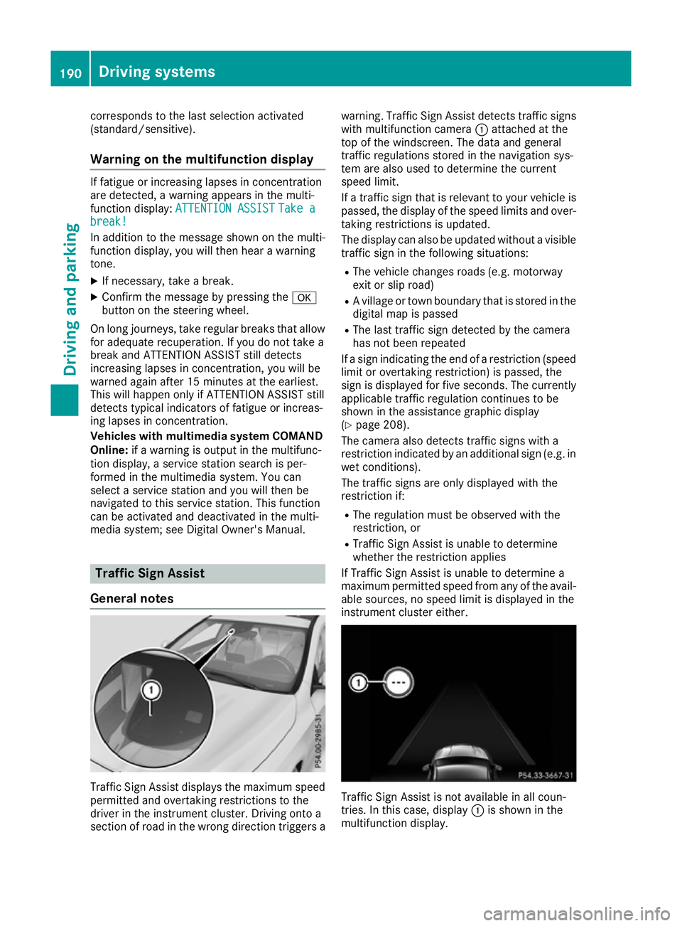
General notes Traffic Sign Assist displays the maximum speed
permitted and overtaking restrictions to the
driver in the instrument cluster. Driving onto a
section of road in the wrong direction triggers a warning. Traffic Sign Assist detects traffic signs
with multifunction camera :attached at the
top of the windscreen. The data and general
traffic regulations stored in the navigation sys-
tem are also used to determine the current
speed limit.
If a traffic sign that is relevant to your vehicle is
passed, the display of the speed limits and over- taking restrictions is updated.
The display can also be updated without a visible
traffic sign in the following situations:
R The vehicle changes roads (e.g. motorway
exit or slip road)
R A village or town boundary that is stored in the
digital map is passed
R The last traffic sign detected by the camera
has not been repeated
If a sign indicating the end of a restriction (speed limit or overtaking restriction) is passed, the
sign is displayed for five seconds. The currently
applicable traffic regulation continues to be
shown in the assistance graphic display
(Y page 208).
The camera also detects traffic signs with a
restriction indicated by an additional sign (e.g. in
wet conditions).
The traffic signs are only displayed with the
restriction if:
R The regulation must be observed with the
restriction, or
R Traffic Sign Assist is unable to determine
whether the restriction applies
If Traffic Sign Assist is unable to determine a
maximum permitted speed from any of the avail- able sources, no speed limit is displayed in the
instrument cluster either. Traffic Sign Assist is not available in all coun-
tries. In this case, display
:is shown in the
multifunction display. 190
Driving systemsDriving and parking
Page 280 of 345
Mercedes-Benz emergency call sys-
tem
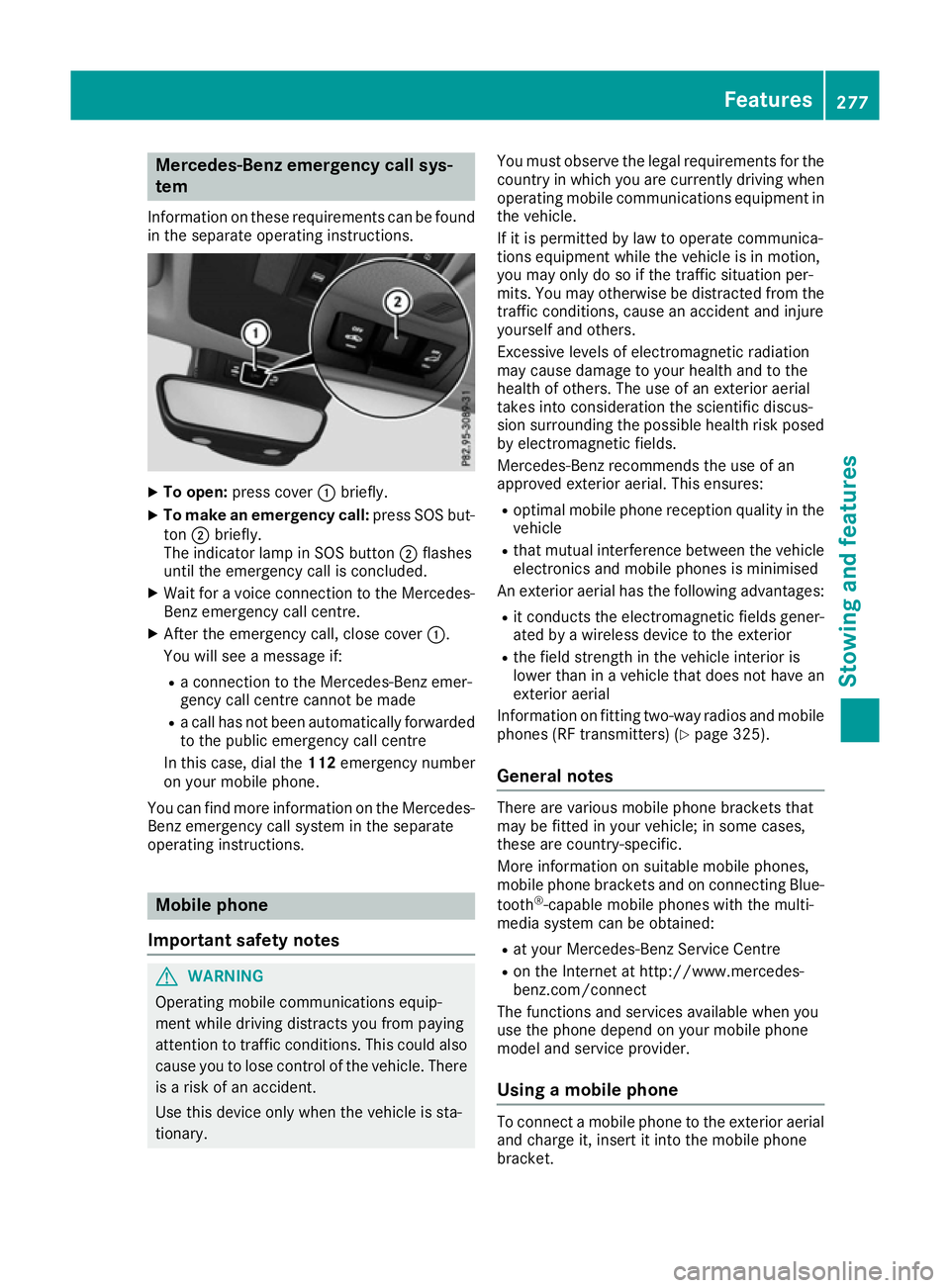
Information on these requirements can be found in the separate operating instructions. X
To open: press cover :briefly.
X To make an emergency call: press SOS but-
ton ;briefly.
The indicator lamp in SOS button ;flashes
until the emergency call is concluded.
X Wait for a voice connection to the Mercedes-
Benz emergency call centre.
X After the emergency call, close cover :.
You will see a message if:
R a connection to the Mercedes-Benz emer-
gency call centre cannot be made
R a call has not been automatically forwarded
to the public emergency call centre
In this case, dial the 112emergency number
on your mobile phone.
You can find more information on the Mercedes- Benz emergency call system in the separate
operating instructions. Mobile phone
Important safety notes G
WARNING
Operating mobile communications equip-
ment while driving distracts you from paying
attention to traffic conditions. This could also cause you to lose control of the vehicle. There
is a risk of an accident.
Use this device only when the vehicle is sta-
tionary. You must observe the legal requirements for the
country in which you are currently driving when
operating mobile communications equipment in the vehicle.
If it is permitted by law to operate communica-
tions equipment while the vehicle is in motion,
you may only do so if the traffic situation per-
mits. You may otherwise be distracted from the
traffic conditions, cause an accident and injure
yourself and others.
Excessive levels of electromagnetic radiation
may cause damage to your health and to the
health of others. The use of an exterior aerial
takes into consideration the scientific discus-
sion surrounding the possible health risk posed
by electromagnetic fields.
Mercedes-Benz recommends the use of an
approved exterior aerial. This ensures:
R optimal mobile phone reception quality in the
vehicle
R that mutual interference between the vehicle
electronics and mobile phones is minimised
An exterior aerial has the following advantages:
R it conducts the electromagnetic fields gener-
ated by a wireless device to the exterior
R the field strength in the vehicle interior is
lower than in a vehicle that does not have an
exterior aerial
Information on fitting two-way radios and mobile phones (RF transmitters) (Y page 325).
General notes There are various mobile phone brackets that
may be fitted in your vehicle; in some cases,
these are country-specific.
More information on suitable mobile phones,
mobile phone brackets and on connecting Blue-
tooth ®
-capable mobile phones with the multi-
media system can be obtained:
R at your Mercedes-Benz Service Centre
R on the Internet at http://www.mercedes-
benz.com/connect
The functions and services available when you
use the phone depend on your mobile phone
model and service provider.
Using a mobile phone To connect a mobile phone to the exterior aerial
and charge it, insert it into the mobile phone
bracket. Features
277Stowing and features Z
Page 303 of 345
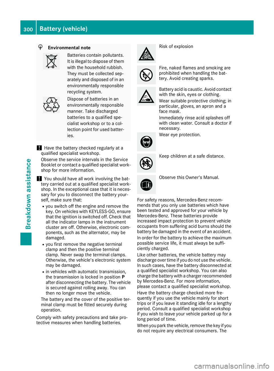
H
Environmental note Batteries contain pollutants.
It is illegal to dispose of them with the household rubbish.
They must be collected sep-
arately and disposed of in anenvironmentally responsible
recycling system. Dispose of batteries in an
environmentally responsible
manner. Take discharged
batteries to a qualified spe-
cialist workshop or to a col-
lection point for used batter-
ies.
! Have the battery checked regularly at a
qualified specialist workshop.
Observe the service intervals in the Service
Booklet or contact a qualified specialist work- shop for more information.
! You should have all work involving the bat-
tery carried out at a qualified specialist work-
shop. In the exceptional case that it is neces-
sary for you to disconnect the battery your-
self, make sure that:
R you switch off the engine and remove the
key. On vehicles with KEYLESS-GO, ensure
that the ignition is switched off. Check that all the indicator lamps in the instrument
cluster are off. Otherwise, electronic com-
ponents, such as the alternator, may be
damaged.
R you first remove the negative terminal
clamp and then the positive terminal
clamp. Never swap the terminal clamps.
Otherwise, the vehicle's electronic system
may be damaged.
R in vehicles with automatic transmission,
the transmission is locked in position P
after disconnecting the battery. The vehicle
is secured against rolling away. You can
then no longer move the vehicle.
The battery and the cover of the positive ter-
minal clamp must be fitted securely during
operation.
Comply with safety precautions and take pro-
tective measures when handling batteries. Risk of explosion
Fire, naked flames and smoking are
prohibited when handling the bat-
tery. Avoid creating sparks.
Battery acid is caustic. Avoid contact
with the skin, eyes or clothing.
Wear suitable protective clothing; in
particular, gloves, an apron and a
face mask.
Immediately rinse acid splashes off
with clean water. Consult a doctor if
necessary. Wear eye protection.
Keep children at a safe distance.
Observe this Owner's Manual.
For safety reasons, Mercedes-Benz recom-
mends that you only use batteries which have
been tested and approved for your vehicle by
Mercedes-Benz. These batteries provide
increased impact protection to prevent vehicle
occupants from suffering acid burns should the battery be damaged in the event of an accident.
In order for the battery to achieve the maximum possible service life, it must always be suffi-
ciently charged.
Like other batteries, the vehicle battery may
discharge over time if you do not use the vehicle.In such cases, have the battery disconnected ata qualified specialist workshop. You can also
charge the battery with a charger recommended
by Mercedes-Benz. For more information,
please contact a qualified specialist workshop.
Have the battery charge checked more fre-
quently if you use the vehicle mainly for short
trips or if you leave it standing idle for a lengthy period. Consult a qualified specialist workshop
if you wish to leave your vehicle parked up for a
long period of time.
When you park the vehicle, remove the key if you do not require any electrical consumers. The 300
Battery (vehicle)Breakdown assistance
Page 304 of 345
vehicle will then use very little energy, thus con-
serving battery power.
If the power supply has been interrupted, e.g. if
the battery was discharged, you will have to:
R set the clock using the multimedia system;
see the separate operating instructions.
R reset the function for folding the exterior mir-
rors in/out automatically, by folding the mir-
rors out once (Y page 104) Charging the battery
G
WARNING
During charging and jump-starting, explosive
gases can escape from the battery. There is a risk of an explosion.
Particularly avoid fire, naked flames, creating
sparks and smoking. Ensure there is sufficient
ventilation while charging and jump-starting.
Do not lean over a battery. G
WARNING
Battery acid is caustic. There is a risk of injury. Avoid contact with the skin, eyes or clothing.
Do not breathe in any battery gases. Do not
lean over the battery. Keep the batteries out
of the reach of children. Immediately rinse off
battery acid thoroughly with plenty of clean
water and seek medical attention at once. G
WARNING
A discharged battery can freeze at tempera-
tures below freezing point. When jump-start-
ing the vehicle or charging the battery, gases can escape from the battery. There is a risk of
an explosion.
Allow the frozen battery to thaw out before
charging it or jump-starting.
! Only use battery chargers with a maximum
charging voltage of 14.8 V.
! Only
charge the battery using the jump-start
connection point.
The jump-starting connection point is in the
engine compartment (Y page 301).
X Open the bonnet.
X Connect the battery charger to the positive
terminal and earth point in the same order as
when connecting the donor battery in the
jump-starting procedure (Y page 301).
If the indicator/warning lamps do not light up in
the instrument cluster at low temperatures, it is very likely that the discharged battery has fro-
zen. In this case, you may neither jump-start the
vehicle nor charge the battery. The service life of a battery that has been thawed may be reduced. The starting characteristics may be impaired,
especially at low temperatures. Have the
thawed battery checked at a qualified specialist workshop.
Only charge the installed battery with a battery
charger which has been tested and approved byMercedes-Benz. A battery charger unit specially
adapted for Mercedes-Benz vehicles and tested
and approved by Mercedes-Benz is available as an accessory. This device permits charging of
the battery while it is installed. Contact a
Mercedes-Benz Service Centre for information
and availability. Read the battery charger's
operating instructions before charging the bat-
tery. Jump-starting
For the jump-starting procedure, use only the jump-starting connection point, consisting of a pos- itive terminal and an earth point, in the engine compartment. G
WARNING
Battery acid is caustic. There is a risk of injury.
Avoid contact with the skin, eyes or clothing. Do not breathe in any battery gases. Do not lean over the battery. Keep the batteries out of the reach of children. Immediately rinse off battery acid
thoroughly with plenty of clean water and seek medical attention at once. Jump-starting
301Breakdown assistance Z
Page 305 of 345
G
WARNING
During charging and jump-starting, explosive gases can escape from the battery. There is a risk of an explosion.
Particularly avoid fire, naked flames, creating sparks and smoking. Ensure there is sufficient
ventilation while charging and jump-starting. Do not lean over a battery. G
WARNING
During the charging process, a battery produces hydrogen gas. If a short circuit occurs or sparks
are created, the hydrogen gas can ignite. There is a risk of an explosion.
R Make sure that the positive terminal of a connected battery does not come into contact with
vehicle parts.
R Never place metal objects or tools on a battery.
R It is important that you observe the described order of the battery terminals when connecting
and disconnecting a battery.
R When jump-starting, make sure that the battery poles with identical polarity are connected.
R It is particularly important to observe the described order when connecting and disconnecting
the jump leads.
R Never connect or disconnect the battery terminals while the engine is running. G
WARNING
A discharged battery can freeze at temperatures below freezing point. When jump-starting the
vehicle or charging the battery, gases can escape from the battery. There is a risk of an explosion.
Allow the frozen battery to thaw out before charging it or jump-starting.
! Vehicles with a petrol engine:
avoid repeated and lengthy starting attempts. Otherwise, the
non-combusted fuel may damage the catalytic converter.
If the indicator/warning lamps do not light up in the instrument cluster at low temperatures, it is very likely that the discharged battery has frozen. In this case you may neither jump-start the vehicle norcharge the battery. Let the battery thaw first. The service life of a battery that has been thawed may
be reduced. The starting characteristics may be impaired, especially at low temperatures. Have the
thawed battery checked at a qualified specialist workshop.
Do not use a rapid charging device to start the vehicle. If your vehicle's battery is discharged, the
engine can be jump-started from another vehicle or from a second battery using jump leads.
Observe the following points:
R The battery is not accessible in all vehicles. If the other vehicle's battery is not accessible, jump-
start the vehicle using a second battery or a jump-starting device.
R Vehicles with a petrol engine: jump-start the vehicle only when the engine and exhaust system
are cold.
R Do not start the engine if the battery is frozen. Let the battery thaw first.
R Jump-starting may be performed only using batteries with a nominal voltage of 12 V.
R Only use jump leads that are not damaged and have a sufficient cross-section and insulated
terminal clamps.
R Make sure that the two vehicles do not touch. 302
Jump-startingBreakdown assistance