warning MERCEDES-BENZ CLK CABRIOLET 2000 A208 Owner's Guide
[x] Cancel search | Manufacturer: MERCEDES-BENZ, Model Year: 2000, Model line: CLK CABRIOLET, Model: MERCEDES-BENZ CLK CABRIOLET 2000 A208Pages: 323, PDF Size: 9.32 MB
Page 72 of 323
Restraint systems
Te ch n ica l
data Instruments
and controlsOperationDrivingInstrument
cluster displayPractical hints Car care Index
Important!
The use of infant or child restraints is required by law in
all 50 states and all Canadian provinces.
Infants and small children should be seated in an
appropriate infant or child restraint system properly
secured by a lap-shoulder belt, and that complies with
U.S. Federal Motor Vehicle Safety Standard 213 and
Canadian Motor Vehicle Safety Standard 213.
A statement by the child restraint manufacturer of
compliance with this standard can be found on the
instruction label on the restraint and in the instruction
manual provided with the restraint.
When using any infant or child restraint system, be sure
to carefully read and follow all manufacturer’s
instructions for installation and use.
Please read and observe warning labels affixed to inside
of vehicle and to infant or child restraints.
Warning!
Children 12 years old and under must never ride in
the front seat, except in a Mercedes-Benz
authorized BabySmart
TM compatible child seat,
which operates with the BabySmart
TM system
installed in the vehicle to deactivate the passenger
front airbag when it is properly installed.
Otherwise they will be struck by the airbag when it
inflates in a crash. If this happens, serious or fatal
injury can result.
According to accident statistics, children are safer
when properly restrained in the rear seating
positions than in the front seating positions.
Infants and small children must ride in back seats
and be seated in an appropriate infant or child
restraint system, which is properly secured with
the vehicle’s seat belt, fully in accordance with the
child seat manufacturer’s instructions.Infants and small children should never share a
seat belt with another occupant. During an
accident, they could be crushed between the
occupant and seat belt.
72
Page 74 of 323
Adjusting telescoping steering column
Te ch n ica l
data Instruments
and controlsOperationDrivingInstrument
cluster displayPractical hints Car care Index
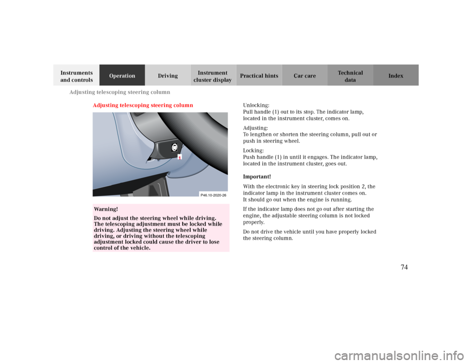
Adjusting telescoping steering columnUnlocking :
Pull handle (1) out to its stop. The indicator lamp,
located in the instrument cluster, comes on.
Ad justing:
To lengthen or shorten the steering column, pull out or
push in steering wheel.
Locking:
Push handle (1) in until it engages. The indicator lamp,
located in the instrument cluster, goes out.
Important!
With the electronic key in steering lock position 2, the
indicator lamp in the instrument cluster comes on.
It should go out when the engine is running.
If the indicator lamp does not go out after starting the
engine, the adjustable steering column is not locked
properly.
Do not drive the vehicle until you have properly locked
the steering column.
Warning!
Do not adjust the steering wheel while driving.
The telescoping adjustment must be locked while
driving. Adjusting the steering wheel while
driving, or driving without the telescoping
adjustment locked could cause the driver to lose
control of the vehicle.
1
P46.10-2020-26
74
Page 77 of 323
Rear view mirrors
Te ch n ica l
data Instruments
and controlsOperationDrivingInstrument
cluster displayPractical hints Car care Index Important!
Electrolyte drops coming into contact with the vehicle
paint finish can only be completely removed while in
their liquid state, by applying plenty of water.
Warning!
In the case of an accident liquid electrolyte may
escape the mirror housing when the mirror glass
breaks.Electrolyte has an irritating effect. Do not allow the
liquid come into contact with eyes, skin, clothing,
or respiratory system. In cases it does, immediately
flush affected area with water, and seek medical
help if necessary.
77
Page 81 of 323
Instrument cluster
Te ch n ica l
data Instruments
and controlsOperationDrivingInstrument
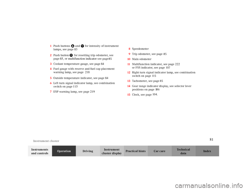
cluster displayPractical hints Car care Index 1Push buttonsVandWfor intensity of instrument
lamps, see page 83
85 2Push buttonJ for resetting trip odometer, see
page85, or
multifunction indicator
see page
104. 3Coolant temperature gauge, see page 84
4Fuel gauge with reserve and fuel cap placement
warning lamp, see page 218
5Outside temperature indicator, see page 84
6Left turn signal indicator lamp, see combination
switch on page115
7ESP warning lamp, see page 2198Speedometer
9Trip odometer, see page
10Main odometer
11Multifunction indicator, see page 222
or FSS indicator, see page 10
12Right turn signal indicator lamp, see combination
switch on page 11
13Tachometer, see page 7
14Gear range indicator display, see selector lever
positions on page 1
15Clock, see page 85 85
86 5
81
Page 84 of 323
Instrument cluster
Te ch n ica l
data Instruments
and controlsOperationDrivingInstrument
cluster displayPractical hints Car care Index
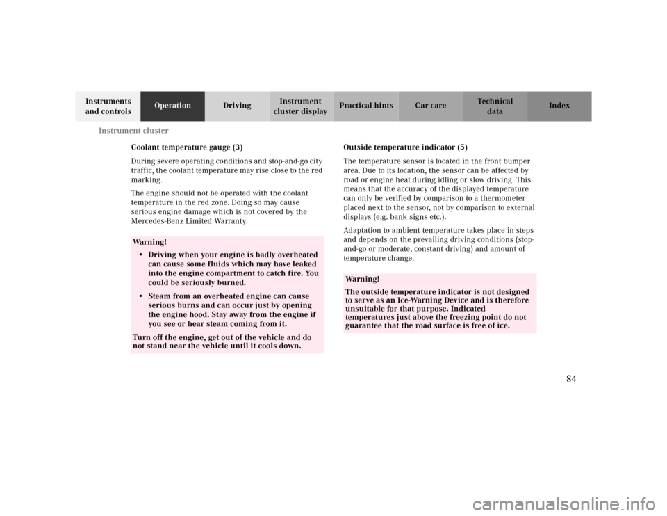
Coolant temperature gauge (3)
During severe operating conditions and stop-and-go city
traffic, the coolant temperature may rise close to the red
marking.
The engine should not be operated with the coolant
temperature in the red zone. Doing so may cause
serious engine damage which is not covered by the
Mercedes-Benz Limited Warranty.Outside temperature indicator (5)
The temperature sensor is located in the front bumper
area. Due to its location, the sensor can be affected by
road or engine heat during idling or slow driving. This
means that the accuracy of the displayed temperature
can only be verified by comparison to a thermometer
placed next to the sensor, not by comparison to external
displays (e.g. bank signs etc.).
Adaptation to ambient temperature takes place in steps
and depends on the prevailing driving conditions (stop-
and-go or moderate, constant driving) and amount of
temperature change.
Warning!
• Driving when your engine is badly overheated
can cause some fluids which may have leaked
into the engine compartment to catch fire. You
could be seriously burned.• Steam from an overheated engine can cause
serious burns and can occur just by opening
the engine hood. Stay away from the engine if
you see or hear steam coming from it.Turn off the engine, get out of the vehicle and do
not stand near the vehicle until it cools down.
Wa r n i n g !
The outside temperature indicator is not designed
to serve as an Ice-Warning Device and is therefore
unsuitable for that purpose. Indicated
temperatures just above the freezing point do not
guarantee that the road surface is free of ice.
84
Page 102 of 323
Multifunction steering wheel, multifunction display
Te ch n ica l
data Instruments
and controlsOperationDrivingInstrument
cluster displayPractical hints Car care Index
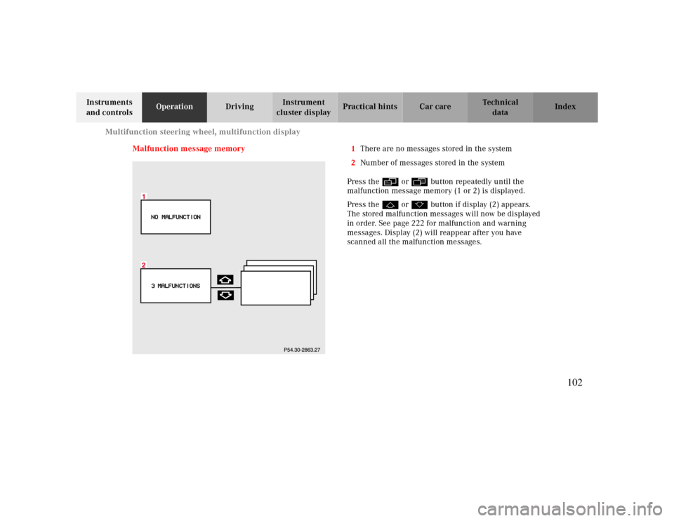
Malfunction message memory 1There are no messages stored in the system
2Number of messages stored in the system
Press the è or ÿ button repeatedly until the
malfunction message memory (1 or 2) is displayed.
Press the j or k button if display (2) appears.
The stored malfunction messages will now be displayed
in order. See page 222for malfunction and warning
messages. Display (2) will reappear after you have
scanned all the malfunction messages.
102
Page 103 of 323
Multifunction steering wheel, multifunction display
Te ch n ica l
data Instruments
and controlsOperationDrivingInstrument
cluster displayPractical hints Car care Index Should any malfunctions be stored while driving, they
will reappear in the display (2) when the electronic key
is in steering lock position 0 or removed from the
steering lock.
Specific malfunctions can be recalled by pressing
button J. Each malfunction or warning message must
be acknowledged by pressing button J. Once all
messages are cancelled, the odometer display should
reappear.
Pressing the J button in the instrument cluster
immediately switches to the next malfunction message.
The malfunction message memory will be cleared when
the electronic key is turned in the steering lock to
position 1 or 2. Should any subsequent malfunctions
occur, they will be displayed in the malfunction
message memory.
Pressing the è or ÿ button displays the next or
previous system.Important!
Malfunction and warning messages are only indicated
for certain systems and displayed to a low level of detail.
The malfunction and warning messages are simply a
reminder with respect to the operation of certain
systems and do not replace the driver’s responsibility to
maintain the vehicle’s operating safety by having all
required maintenance and safety checks performed on
the vehicle and by bringing the vehicle to an authorized
Mercedes-Benz Center to address the malfunction and
warning messages. See page216.
103
Page 107 of 323
Flexible service system
Te ch n ica l
data Instruments
and controlsOperationDrivingInstrument
cluster displayPractical hints Car care Index Flexible service system (FSS)
(service indicator)
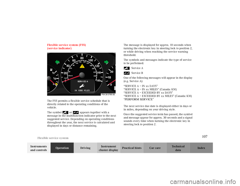
The FSS permits a flexible service schedule that is
directly related to the operating conditions of the
vehicle.
The symbol 9 or ½ appears together with a
message in the multifunction indicator prior to the next
suggested service. Depending on operating conditions
throughout the year, the next service is calculated and
displayed in days or distance remaining.The message is displayed for approx. 10 seconds when
turning the electronic key in steering lock to position 2,
or while driving when reaching the service warning
threshold.
The symbols and messages indicate the type of service
to be performed:
9Service A
½Service B
One of the following messages will appear in the display
(e.g. Service A):
“SERVICE A – IN xx DAYS”
“SERVICE A – IN xx MILES” (Canada: KM)
“SERVICE A – EXCEEDED BY xx DAYS”
“SERVICE A – EXCEEDED BY xx MILES” (Canada: KM)
“PERFORM SERVICE"
The next service due date is displayed either in days or
in miles, depending on your driving style.
Once the suggested service term has passed, the symbol
and message appear for approx. 30 seconds and a signal
sounds every time when turning the electronic key in
steering lock to position 2.
10
0
406080
60
40
mph
20km/h
20100
120
140160
80
100
180
200
220
240 160 120 140
107
Page 111 of 323
Engine oil level indicator
Te ch n ica l
data Instruments
and controlsOperationDrivingInstrument
cluster displayPractical hints Car care Index One of the following messages will subsequently appear
on the indicator:
“ENGINE OIL LEVEL – O.K.”
No oil needs to be added.
“ENGINE OIL LEVEL – ADD 1.0 QUART”
(Canada: 1.0 L)
“ENGINE OIL LEVEL – ADD 1.5 QUART”
(Canada: 1.5 L)
“ENGINE OIL LEVEL – ADD 2.0 QUART”
(Canada: 2.0 L)
See page246for instructions on adding engine oil.
“ENGINE OIL LEVEL – REDUCE OIL LEVEL”
Do not overfill the engine.
Excessive oil must be siphoned or drained off. It could
cause damage to the engine and catalytic converter not
covered by the Mercedes-Benz Limited Warranty.
The message “PERF. SERV. ON TIME” (perform service
[engine oil level check] on time) will be displayed if a
proper oil level check cannot be performed. The engine
oil level check can be repeated after a short time.Perform the engine oil level check with the dipstick, if it
cannot be completed via the multifunction display.
See page246
In this case we recommend that you have the system
checked at a Mercedes-Benz Center.
Note:
See malfunction and warning messages on page222
and page232if an engine oil level indicator appears on
the multifunction display when the engine is running.
The engine oil level cannot be checked while the engine
is running. The “ENGINE OIL LEVEL – NOT WHEN
ENGINE ON” message will appear.
Engine oil consumption
Engine oil consumption checks should only be made
after the break-in period. During the break-in period,
higher oil consumption may be noticed and is normal.
Frequent driving at high engine speeds results in
increased consumption.
111
Page 113 of 323
Exterior lamp switch
Te ch n ica l
data Instruments
and controlsOperationDrivingInstrument
cluster displayPractical hints Car care Index Notes:
With the electronic key removed and the driver’s door
open, a warning sounds and the message “SWITCH OFF
LIGHTS” in the multifunction indicator appears if the
vehicle’s exterior lamps (except standing lamps) are not
switched off.
Fog lamps will operate with the parking lamps and/or
the low beam headlamps on. Fog lamps should only be
used in conjunction with low beam headlamps. Consult
your State or Province Motor Vehicle Regulations
regarding allowable lamp operation.
Fog lamps are automatically switched off when the
exterior lamp switch is turned to position D.Daytime running lamps (Canada only)
When the engine is running and the selector lever is in
a driving position, the low beam headlamps (includes
parking lamps, side marker lamps, taillamps and
license plate lamps) are automatically switched on.
When shifting from a driving position to position “N”
or “P”, the low beam switches off (2 seconds delay).
For nighttime driving the exterior lamp switch should
be turned to position B to permit activation of the
high beam headlamps.
Night security illumination
When exiting the vehicle after driving with the exterior
lamps on, they switch on again for added illumination
for approximately 30 seconds after closing the last door.
The lamp-on time period can be changed at your
Mercedes-Benz Center.
113