alarm MERCEDES-BENZ CLK320 CABRIOLET 2003 C208 User Guide
[x] Cancel search | Manufacturer: MERCEDES-BENZ, Model Year: 2003, Model line: CLK320 CABRIOLET, Model: MERCEDES-BENZ CLK320 CABRIOLET 2003 C208Pages: 341, PDF Size: 10.33 MB
Page 42 of 341
39 Antitheft alarm system
Te ch n i c a l
data Instruments
and controlsOperationDrivingInstrument
cluster displayPractical hints Car care Index Antitheft alarm system
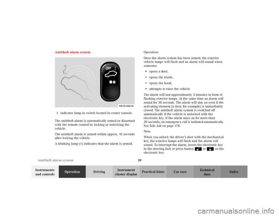
1Indicator lamp in switch located in center console
The antitheft alarm is automatically armed or disarmed
with the remote control by locking or unlocking the
vehicle.
The antitheft alarm is armed within approx. 10 seconds
after locking the vehicle.
A blinking lamp (1) indicates that the alarm is armed.Operation:
Once the alarm system has been armed, the exterior
vehicle lamps will flash and an alarm will sound when
someone:
•opens a door,
•opens the trunk,
•opens the hood,
•attempts to raise the vehicle.
The alarm will last approximately 3 minutes in form of
flashing exterior lamps. At the same time an alarm will
sound for 30 seconds. The alarm will stay on even if the
activating element (a door, for example) is immediately
closed. The antitheft alarm system is switched off
automatically if the vehicle is unlocked with the
electronic key. If the alarm stays on for more than
20 seconds, an emergency call is initiated automatically.
See Tele Aid on page 178.
Note:
When you unlock the driver’s door with the mechanical
key, the exterior lamps will flash and the alarm will
sound. To interrupt the alarm, insert the electronic key
in the steering lock or press buttonŒ or‹ on the
electronic key.
1
Page 43 of 341
40 Tow-away alarm
Te ch n i c a l
data Instruments
and controlsOperationDrivingInstrument
cluster displayPractical hints Car care Index
Tow-away alarm
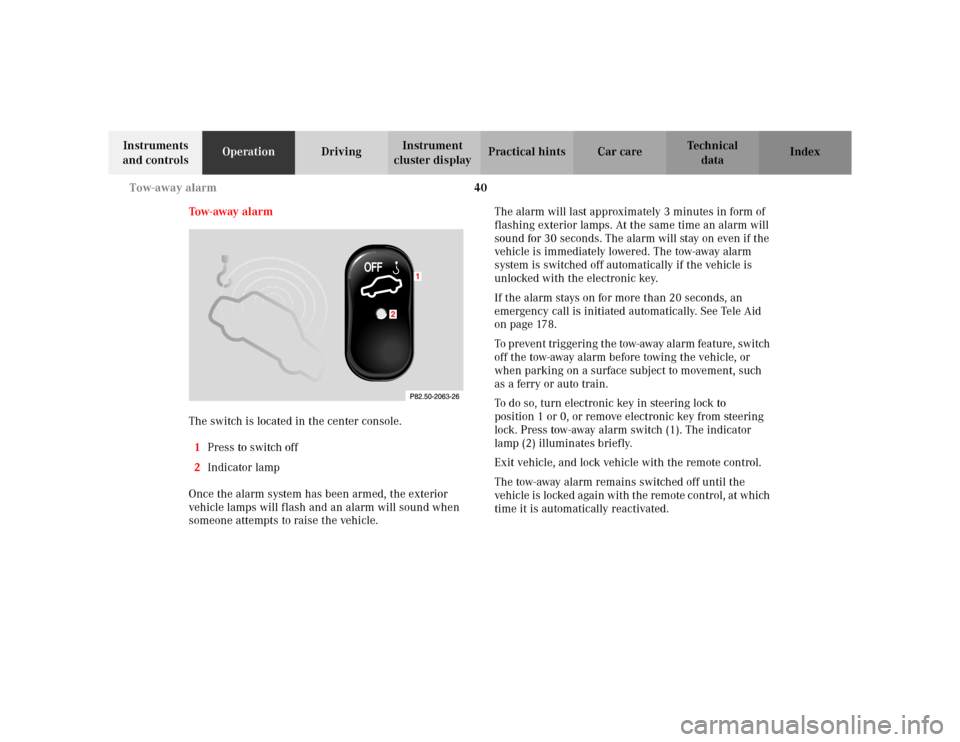
The switch is located in the center console.
1Press to switch off
2Indicator lamp
Once the alarm system has been armed, the exterior
vehicle lamps will flash and an alarm will sound when
someone attempts to raise the vehicle.The alarm will last approximately 3 minutes in form of
flashing exterior lamps. At the same time an alarm will
sound for 30 seconds. The alarm will stay on even if the
vehicle is immediately lowered. The tow-away alarm
system is switched off automatically if the vehicle is
unlocked with the electronic key.
If the alarm stays on for more than 20 seconds, an
emergency call is initiated automatically. See Tele Aid
on page 178.
To prevent triggering the tow-away alarm feature, switch
off t he tow-away alarm b efor e towin g the vehic le, or
when parking on a surface subject to movement, such
as a ferry or auto train.
To do so, turn electronic key in steering lock to
position 1 or 0, or remove electronic key from steering
lock. Press tow-away alarm switch (1). The indicator
lamp (2) illuminates briefly.
Exit vehicle, and lock vehicle with the remote control.
The tow-away alarm remains switched off until the
vehicle is locked again with the remote control, at which
time it is automatically reactivated.
Page 181 of 341
178 Tele Aid
Te ch n i c a l
data Instruments
and controlsOperationDrivingInstrument
cluster displayPractical hints Car care Index
Te l e A i d (optional for Canada)
Important!
The initial activation of the Tele Aid system may only be
performed by completing the subscriber agreement and
placing an acquaintance call using the SOS button.
Failure to complete either of these steps will result in a
system that is not activated. If the system is not
activated the indicator lamp in the SOS button stays on
after turning electronic key in starter switch to
position 2 and the message “TELE AID – NOT
ACTIVATED” will be shown in the multifunction display
for approx. 10 seconds.
If you have any questions regarding activation, please
call the Response Center at 1-800-756-9018 (in the USA)
or 1-888-923-8367 (in Canada).
(Te l ematic Alarm Identification on Demand)
The Tele Aid system consists of three types of response;
automatic and manual emergency, roadside assistance
and information.
The Tele Aid system is operational providing that the
vehicle’s battery is charged, properly connected, not
damaged and cellular and GPS coverage is available.The speaker volume of a Tele Aid call can be adjusted
when using the volume control on the multifunction
steering wheel, for raising press buttonæ and for
lowering press buttonç.
To activate, press the SOS button, the Roadside
Assistance button• or the Information button¡,
depending on the type of response required.
Shortly after the completion of your Acquaintance Call,
you will receive a user ID and password via first call
mail. By visiting www.mbusa.com and selecting “Tele
Aid” (USA only), you will have access to account
information, remote door unlock, profile and more.
Important!
Tele Aid utilizes the cellular network for
communication and the GPS (Global Positioning
System) satellites for vehicle location. If either of these
signals are unavailable, the Tele Aid system may not
function and if this occurs, assistance must be
summoned by other means.
Page 182 of 341
179 Tele Aid
Te ch n i c a l
data Instruments
and controlsOperationDrivingInstrument
cluster displayPractical hints Car care Index System self-check
Initially, after turning the electronic key in starter
switch to position 2, malfunctions are detected and
indicated (the indicator lamps in the SOS button, the
Roadside Assistance button• and the Information
button¡ stay on longer than 10 seconds or do not
come on). The message “TELE AID – VISIT
WORKSHOP” appears for approx. 10 seconds in the
multifunction display. Important!
Always make sure that the indicator lamps in the is not
displayed in the multifunction display after the system
self check.
If a malfunction is indicated as outlined above, have the
system checked at the nearest Mercedes-Benz Center as
soon as possible.
Emergency calls
An emergency call is initiated automatically:
•following an accident in which the Emergency
Tensioning Devices (ETDs) or airbags deploy,
•if the antitheft alarm or the tow away alarm stays on
for more than 20 seconds, see pages 39 and 40.
An emergency call can also be initiated manually by
opening the cover next to the inside rear view mirror
labeled SOS, then briefly pressing the button located
under the cover. See below for instructions on initiating
an emergency call manually.
Once the emergency call is in progress, the indicator
lamp in the SOS button will begin to flash. The message
“EMERGENCY CALL – CONNECTING CALL” appears in
the multifunction display. When the connection is
Wa r n i n g !
If the indicator lamps in the SOS button, in the
“Roadside Assistance” button and/or in the
“Information” button do not come on during the
system self-check or if any of these indicators
remain illuminated constantly in red and/or the
message “TELE AID - VISIT WORKSHOP” is
displayed in the multifunction display after the
system self-check, a malfunction in the system has
been detected.If a malfunction is indicated as outlined above, the
system may not operate as expected. Have the
system checked at the nearest Mercedes-Benz
Center as soon as possible.
Page 244 of 341
241 Malfunction and warning messages
Te ch n i c a l
data Instruments
and controlsOperation DrivingInstrument
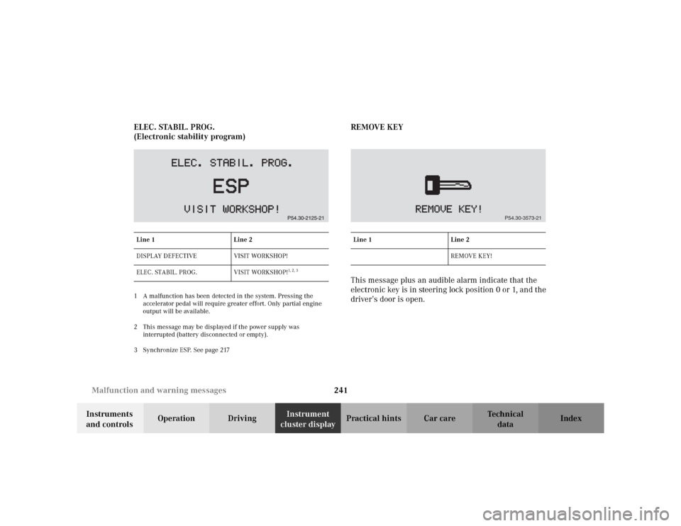
cluster displayPractical hints Car care Index ELEC. STABIL. PROG.
(Electronic stability program)
1 A malfunction has been detected in the system. Pressing the
accelerator pedal will require greater effort. Only partial engine
output will be available.
2 This message may be displayed if the power supply was
interrupted (battery disconnected or empty).
3 Synchronize ESP. See page 217
REMOVE KEY
This message plus an audible alarm indicate that the
electronic key is in steering lock position 0 or 1, and the
driver’s door is open.
Line 1 Line 2
DISPLAY DEFECTIVE VISIT WORKSHOP!
ELEC. STABIL. PROG. VISIT WORKSHOP!
1, 2 , 3
Line 1 Line 2
REMOVE KEY!
P54.30-3573-21
Page 276 of 341
273 Towing
Te ch n i c a l
data Instruments
and controlsOperation DrivingInstrument
cluster displayPractical hintsCar care Index Important!
5. Start engine of the vehicle with the charged battery
and run at high idle. Make sure the cables are not
on or near pulleys, fans, or other parts that move
when the engine is started. Allow the discharged
battery to charge for a few minutes. Start engine of
the disabled vehicle in the usual manner.
6. After the engine has started, remove jumper cables
by exactly reversing the above installation
sequence, starting with the last connection made
first. When removing each clamp, make sure that it
does not touch any other metal while the other end
is still attached to a battery.
Notes:
If engine does not run after several unsuccessful
starting attempts, have it checked at the nearest
authorized Mercedes-Benz Center.
Excessive unburned fuel generated by repeated failed
starting attempts may damage the catalytic converter.Tow i n g t h e v e h i c l e
Mercedes-Benz recommends that the vehicle be
transported with all wheels off the ground using flatbed
or appropriate wheel lift/ dolly equipment. This method
is preferable to other types of towing.
Caution!
Use flatbed or wheel lift/ dolly equipment with key in
steering lock turned to position 0.
Do not tow with sling- type equipment. Towing with
sling- type equipment over bumpy roads will damage
radiator and supports.
To prevent damage during transport, do not tie down
vehicle by its chassis or suspension parts.
Switch off the tow-away alarm (see page 40) as well as
the ESP (see page 218).
When circumstances do not permit the recommended
towing methods, the vehicle may be towed with all
wheels on the ground or front wheels raised only so far
as necessary to have the vehicle moved to a safe location
where the recommended towing methods can be
employed.
Page 327 of 341
324 Index
Te ch n i c a l
data Instruments
and controlsOperation DrivingInstrument
cluster displayPractical hints Car careIndex
Index
AABS (Antilock brake system) ....................................... 214
Malfunction indicator lamp..................................... 227
ABS-SYSTEM - malfunction and
warning messages ......................................................... 233
Adjusting headlamp aim............................................... 282
Adjusting telescoping steering column ........................ 73
Air conditioner refrigerant............................................ 318
Air distribution .............................................................. 120
Air volume ...................................................................... 120
Airbag deactivation system ............................................ 59
Airbag OFF indicator lamp ........................................... 228
Airbags .............................................................................. 61
Alarm system ............................................................. 39, 40
Antenna
Removal ...................................................................... 295
Anticorrosion/antifreeze .................... 208, 254, 316, 321
Antiglare night position.................................................. 74
Antilock brake system (ABS) ....................................... 214
Malfunction indicator lamp..................................... 227
Antitheft alarm system ................................................... 39
Aquaplaning ...................................................................205Armrest, rear bench ....................................................... 152
Ashtray
Center console, front ................................................ 150
Audio system ..................................................................123
Anti-theft system ....................................................... 125
Button and soft key operation ................................. 126
Cassette mode ............................................................ 131
CD changer ................................................................. 136
CD mode ..................................................................... 135
Operating and display elements .............................124
Operating safety ........................................................ 123
Operation ....................................................................127
Operation – audio and telephone ........................... 123
Radio mode ................................................................ 129
Telephone operation ................................................. 139
Audio systems ................................................................... 89
Cassette player ............................................................ 91
CD player ......................................................................90
Radio ............................................................................. 89
Automatic central locking .............................................. 34
Automatic climate control ............................................ 116
Air distribution .......................................................... 120
Air recirculation ........................................................ 121
Air volume.................................................................. 120
Basic setting............................................................... 118
Defogging windows ................................................... 119
Page 337 of 341
334 Index
Te ch n i c a l
data Instruments
and controlsOperation DrivingInstrument
cluster displayPractical hints Car careIndex
Telephone book ........................................................... 92
Telephones and two-way radios ................................... 174
Telescoping steering column
Adjusting ...................................................................... 73
Indicator lamp ...........................................................228
Telescoping steering column - malfunction and
warning messages ......................................................... 239
The first 1 000 miles ..................................................... 175
Tire inflation pressure .................................................. 268
Tire speed rating ............................................................206
Tire traction .................................................................... 206
Tires ................................................................................. 322
Driving instructions ................................................. 204
Rims and tires ........................................................... 312
Rotating wheels ......................................................... 259
Tire inflation pressure ............................................. 268
Tire replacement ....................................................... 258
Winter driving instructions...................................... 207
Tool kit
See Vehicle tools ....................................................... 256
Tow-away alarm ................................................................ 40
Towing the vehicle ......................................................... 273
Transmission .................................................................. 191
Transmission selector lever, manually
unlocking ....................................................................... 276
Traveling abroad ............................................................209Trip and main odometer and sub menu ....................... 88
Trip computer ................................................................... 98
Trip odometer ................................................................... 83
Trunk .................................................................................35
Opening ........................................................................ 28
Release switch ............................................................. 37
Trunk lamp........................................................................ 36
Trunk lid
Emergency release ...................................................... 38
Release switch ............................................................. 37
Turn signal failure ......................................................... 113
Turn signals .................................................................... 113
VVanity mirrors ................................................................ 146
Vehicle jack .................................................................... 257
Vehicle tools ................................................................... 256WWa r n i n g l a m p s
See Indicator lamps in the instrument cluster .......80
Warning message memory ........................................... 100
Warranty coverage ........................................................ 308