manual transmission MERCEDES-BENZ CLK55AMG 2002 C208 Owner's Manual
[x] Cancel search | Manufacturer: MERCEDES-BENZ, Model Year: 2002, Model line: CLK55AMG, Model: MERCEDES-BENZ CLK55AMG 2002 C208Pages: 330, PDF Size: 15.62 MB
Page 7 of 330
4 Contents
Malfunction and
indicator lamps in the
center console ........................... 231
AIRBAG OFF indicator lamp ..... 231
Malfunction and
warning messages in the
multifunction display ...............232
DISPLAY DEFECTIVE
(engine control unit) ..................233
DISPLAY DEFECTIVE
(several systems) ........................233
BATTERY/ALTERNATOR ...........234
ABS-SYSTEM ...............................235
BRAKE ASSIST ...........................235
BRAKE LINING WEAR ..............236
BRAKE FLUID .............................236
PARKING BRAKE .......................237
ENGINE FAN ...............................237
COOLANT
(coolant level) .............................238
COOLANT TEMP.
(coolant temperature) ................239
LIGHTING SYSTEM ....................240
LIGHT SENSOR ........................... 241STEER. WHEEL ADJUST. .......... 241
ENGINE OIL LEVEL ................... 242
ELEC. STABIL. PROGRAM.
(Electronic stability
program) ..................................... 243
REMOVE KEY ............................. 243
WASHER FLUID ......................... 244
TELE AID ..................................... 245
Practical hintsFirst aid kit ..................................... 248
Shelf below rear window .............. 248
Stowing things in
the vehicle ................................. 248
Fuses ............................................... 249
Hood ................................................ 251
Checking engine oil level ............. 253
Automatic transmission
fluid level ................................... 254
Coolant level ................................... 254
Adding coolant ........................... 255
Windshield washer / headlamp
cleaning system ........................ 256Windshield and headlamp
washer fluid mixing ratio .........256
Spare wheel, vehicle tools,
storage compartment ................257
Vehicle jack .....................................258
Wheels .............................................259
Tire replacement ........................259
Rotating wheels ..........................260
Spare wheel .................................... 261
Changing wheels ...........................262
Tire inflation pressure ..................267
Battery .............................................268
Jump starting ..................................270
Towing the vehicle .........................272
Transmission selector lever,
manually unlocking ................... 274
Exterior lamps ................................275
Headlamp assembly ................... 276
Taillamp assemblies ..................278
Adjusting headlamp aim ...............280
Changing batteries in
the electronic key .....................283
Synchronizing remote
control ..........................................285
J_C208_II.book Seite 4 Donnerstag, 31. Mai 2001 10:13 10
Page 189 of 330
186 Tele Aid
Technical
data Instruments
and controlsOperationDrivingInstrument
cluster displayPractical hints Car care Index
Tele Aid system could not initiate an Information call
(e.g. the relevant cellular phone network is not
available). The message “INFO – CALL FAILED” appears
in the multifunction display.
Information calls can be terminated using the
ìbutton on the multifunction steering wheel.
Important!
If the indicator lamps do not start flashing after
pressing one of the buttons or remain illuminated (in
red) at any time, the Tele Aid system has detected a fault
or the service is not currently active, and may not
initiate a call. Visit your Mercedes-Benz Center and
have the system checked or contact the Response Center
at 1-800-756-9018 (in the USA) or 1-888-923-8367 (in
Canada) as soon as possible.Upgrade Signals
Tele Aid system processes calls using the following
priority.
•Automatic emergency – First priority
•Manual emergency – Second priority
•Roadside assistance – Third priority
•Information – Fourth priority
Should a higher priority call be initiated while you are
connected, an upgrade (alternating) tone will be heard,
and the appropriate indicator lamp will flash. If certain
information such as vehicle identification number or
customer information is not available, the operator may
need to retransmit. During this time you will hear a
chirp and voice contact will be interrupted. Voice
contact will resume once the retransmission is
completed. Once a call is concluded, a chirp will be
heard and the appropriate indicator lamp will stop
flashing. The COMAND system operation will resume
(only vehicles with COMAND).
J_C208_II.book Seite 186 Donnerstag, 31. Mai 2001 10:13 10
Page 199 of 330
196 Automatic transmission
Technical
data Instruments
and controlsOperationDrivingInstrument
cluster displayPractical hints Car care Index
Selector lever position
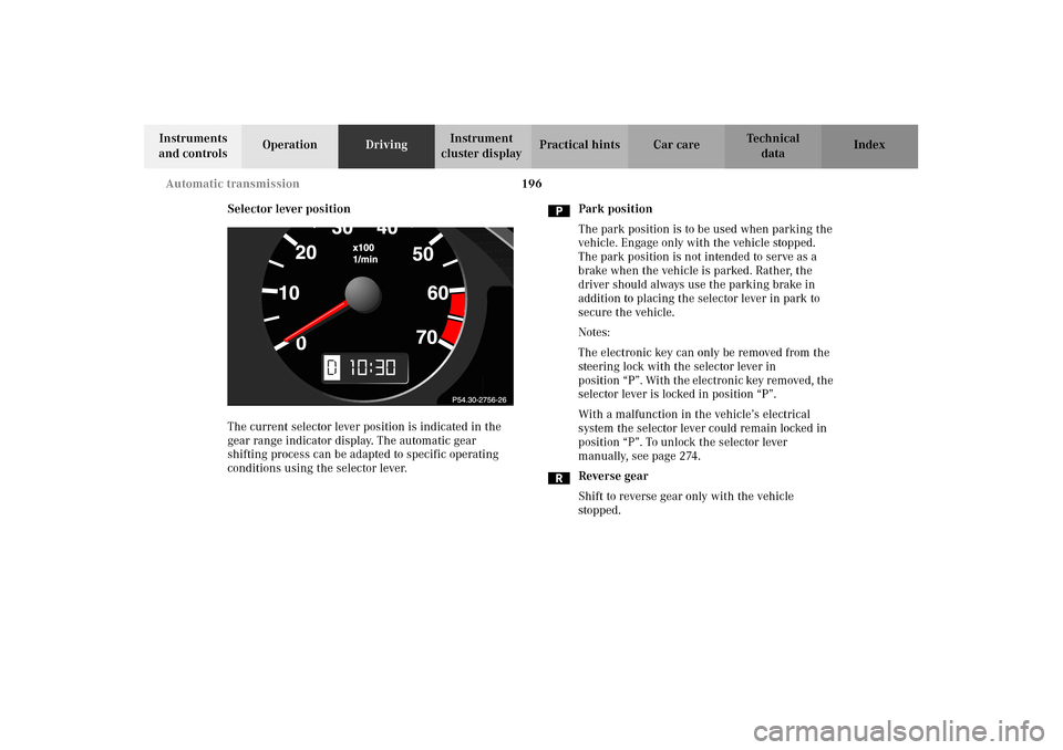
The current selector lever position is indicated in the
gear range indicator display. The automatic gear
shifting process can be adapted to specific operating
conditions using the selector lever.Park position
The park position is to be used when parking the
vehicle. Engage only with the vehicle stopped.
The park position is not intended to serve as a
brake when the vehicle is parked. Rather, the
driver should always use the parking brake in
addition to placing the selector lever in park to
secure the vehicle.
Notes:
The electronic key can only be removed from the
steering lock with the selector lever in
position “P”. With the electronic key removed, the
selector lever is locked in position “P”.
With a malfunction in the vehicle’s electrical
system the selector lever could remain locked in
position “P”. To unlock the selector lever
manually, see page 274.
Reverse gear
Shift to reverse gear only with the vehicle
stopped.
10
J_C208_II.book Seite 196 Donnerstag, 31. Mai 2001 10:13 10
Page 204 of 330
201 Automatic transmission
Technical
data Instruments
and controlsOperationDrivingInstrument
cluster displayPractical hints Car care Index Caution!
Never change the pr ogram mod e when t he se lec tor lever
is out of position “P”. It could result in a change of
driving characteristics for which you may not be
prepared.
Important!
Always be certain of the program mode selected since
the vehicle driving characteristics change with the
selection of the program mode.
Dependent on the program mode selector switch
position “S” or “W” and the gear selector lever in
position “R”, the ratio of power transmission changes.
Emergency operation (Limp home mode)
If vehicle acceleration worsens or the transmission no
longer shifts, the transmission is most likely operating
in Limp home mode which engages when there is a
malfunction of the transmission. This condition may be
accompanied by the “CHECK ENGINE” malfunction
indicator lamp in the instrument cluster coming on.In this mode only the 2nd gear or reverse gear can be
activated.
To engage 2nd gear or reverse:
1. S to p t he ve hi c l e .
2. Move selector lever to position “P”.
3. Turn off the engine.
4. Wait approx. 10 seconds.
5. Restart the engine.
6. Move selector lever to position “D” (for 2nd gear), or
move selector lever to position “R” (for reverse gear).
Have the transmission checked at your authorized
Mercedes-Benz Center as soon as possible.
With a malfunction in the vehicle’s electrical system the
selector lever may be locked in position “P”. To unlock
the selector lever manually, see page 274.
J_C208_II.book Seite 201 Donnerstag, 31. Mai 2001 10:13 10
Page 250 of 330
247 Contents – Practical hints
Technical
data Instruments
and controlsOperation DrivingInstrument
cluster displayPractical hintsCar care Index
Practical hintsFirst aid kit .....................................248
Shelf below rear window ..............248
Stowing things in
the vehicle ..................................248
Fuses ................................................249
Hood ................................................. 251
Checking engine oil level .............253
Automatic transmission
fluid level ...................................254
Coolant level ...................................254
Adding coolant ...........................255
Windshield washer / headlamp
cleaning system .........................256
Windshield and headlamp
washer fluid mixing ratio .........256Spare wheel, vehicle tools,
storage compartment ............... 257
Vehicle jack .................................... 258
Wheels ............................................ 259
Tire replacement ....................... 259
Rotating wheels ......................... 260
Spare wheel .................................... 261
Changing wheels ........................... 262
Tire inflation pressure ................. 267
Battery ............................................. 268
Jump starting ................................. 270
Towing the vehicle ........................ 272
Transmission selector lever,
manually unlocking ...................274
Exterior lamps ............................... 275
Headlamp assembly ...................276
Taillamp assemblies .................. 278Adjusting headlamp aim ...............280
Changing batteries in
the electronic key .....................283
Synchronizing remote
control ..........................................285
Emergency operation of
sliding/pop-up roof ...................286
Manual release for
fuel filler flap .............................287
Replacing wiper
blade insert ................................287
Roof rack .........................................289
J_C208_II.book Seite 247 Donnerstag, 31. Mai 2001 10:13 10
Page 277 of 330
274 Towing
Technical
data Instruments
and controlsOperation DrivingInstrument
cluster displayPractical hintsCar care Index
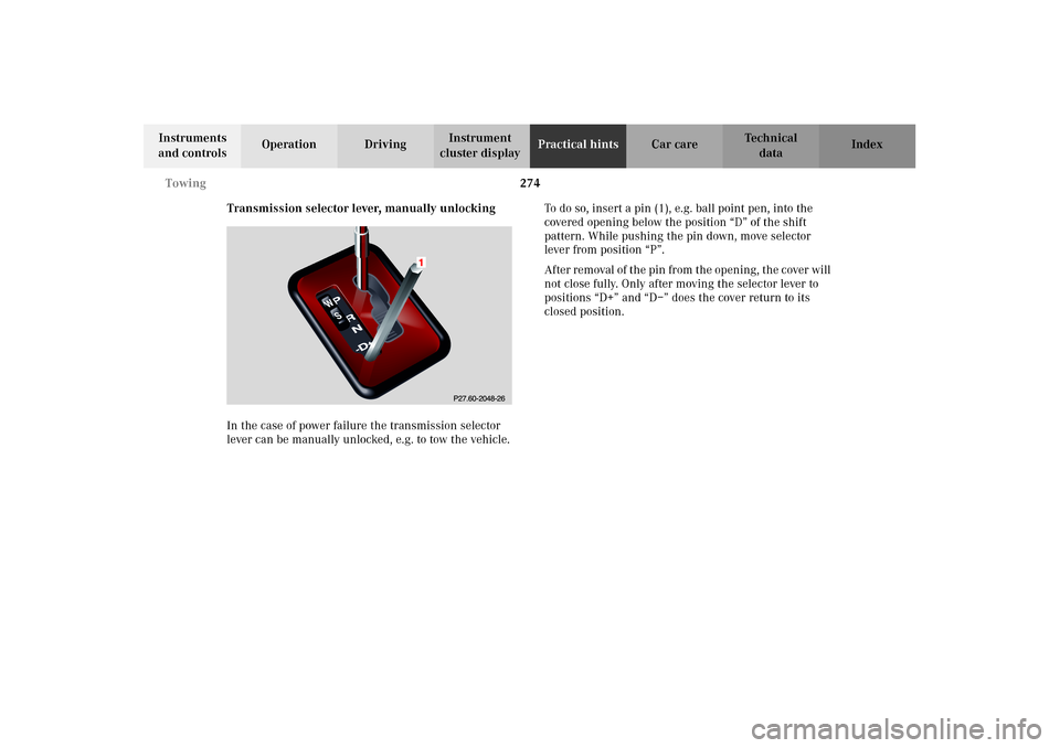
Transmission selector lever, manually unlocking
In the case of power failure the transmission selector
lever can be manually unlocked, e.g. to tow the vehicle.To do so, insert a pin (1), e.g. ball point pen, into the
covered opening below the position “D” of the shift
pattern. While pushing the pin down, move selector
lever from position “P”.
After removal of the pin from the opening, the cover will
not close fully. Only after moving the selector lever to
positions “D+” and “D–” does the cover return to its
closed position.
J_C208_II.book Seite 274 Donnerstag, 31. Mai 2001 10:13 10
Page 317 of 330
314 Index
Technical
data Instruments
and controlsOperation DrivingInstrument
cluster displayPractical hints Car careIndex
Basic setting .............................................................. 124
Defogging windows .................................................. 125
Defrosting ................................................................... 125
Display and controls ................................................. 124
Dust filter ................................................................... 128
Economy ..................................................................... 125
Rear window defroster ............................................. 126
Residual engine heat utilization (REST) ............... 127
Special settings ......................................................... 125
Automatic transmission ............................................... 193
Emergency Operation .............................................. 201
Fluid level ...................................................................254
Program mode selector switch ............................... 200
Selector lever position .............................................. 196
Transmission selector lever,
manually unlocking ............................................. 274
BBabySmart
TM airbag deactivation system ..................... 65
Self-test ......................................................................... 66
Backrest, front seat .......................................................... 54
BAS (Brake assist system) ............................................ 214
Malfunction indicator lamp ..................................... 229Battery ............................................................................ 268
Battery recycling ...................................................... 269
BATTERY/ALTERNATOR -
malfunction and warning messages ..................... 234
Block heater .................................................................... 211
BRAKE ASSIST - malfunction
and warning messages ............................................ 235
Brake assist system (BAS) ............................................ 214
Malfunction indicator lamp .................................... 229
Brake fluid .................................................... 204, 227, 307
Capacity ..................................................................... 305
BRAKE FLUID - malfunction
and warning messages ............................................ 236
BRAKE LINING WEAR - malfunction
and warning messages ............................................ 236
Brake pad wear .............................................................. 236
Brake warning lamp ..................................................... 227
Brake fluid low ......................................................... 227
Brakes .................................................... 202, 204, 214, 219
Bulbs
See Replacing bulbs ................................................. 275
J_C208_II.book Seite 314 Donnerstag, 31. Mai 2001 10:13 10
Page 326 of 330
323 Index
Technical
data Instruments
and controlsOperation DrivingInstrument
cluster displayPractical hints Car careIndex TELE AID - malfunction and warning messages ...... 245
Telephone .......................................................................... 98
General notes ............................................................. 164
Incoming call ............................................................. 102
Redialing .................................................................... 100
Telephone book ........................................................... 98
Telephones and two-way radios ....................................176
Telescoping steering column
Adjusting ...................................................................... 79
Indicator lamp ...........................................................230
Telescoping steering column - malfunction
and warning messages ............................................ 241
The first 1 000 miles ..................................................... 177
Tire inflation pressure .................................................. 267
Tire traction .................................................................... 208
Tires ..................................................................................311
Driving instructions ................................................. 206
Rims and tires ...........................................................302
Rotating wheels ......................................................... 260
Tire inflation pressure ............................................. 267
Tire replacement ....................................................... 259
Winter driving instructions .................................... 209
Tool kit
See Vehicle tools ....................................................... 257Tow-away alarm ................................................................44
Towing the vehicle ........................................................ 272
Transmission .................................................................. 193
Transmission selector lever,
manually unlocking .................................................. 274
Traveling abroad ............................................................ 211
Trip computer ................................................................. 104
Trip odometer ................................................................... 89
Trunk .................................................................................37
Opening ........................................................................ 30
Release switch ............................................................. 40
Trunk lamp ....................................................................... 39
Trunk lid
Emergency release ................................................ 41, 42
Release switch ............................................................. 40
Turn signal failure ......................................................... 119
Turn signals .................................................................... 119
VVanity mirrors ................................................................ 153
Vehicle jack .................................................................... 258
Vehicle tools ................................................................... 257
J_C208_II.book Seite 323 Donnerstag, 31. Mai 2001 10:13 10