wheel bolts MERCEDES-BENZ CLS 2010 Owners Manual
[x] Cancel search | Manufacturer: MERCEDES-BENZ, Model Year: 2010, Model line: CLS, Model: MERCEDES-BENZ CLS 2010Pages: 308, PDF Size: 5.71 MB
Page 184 of 308
X
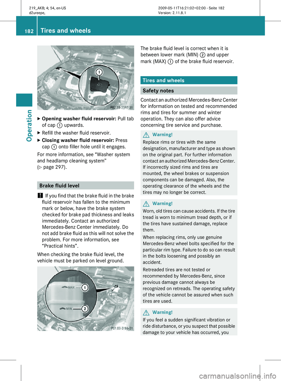
Opening washer fluid reservoir: Pull tab
of cap : upwards.
X Refill the washer fluid reservoir.
X Closing washer fluid reservoir: Press
cap : onto filler hole until it engages.
For more information, see “Washer system
and headlamp cleaning system”
(Y page 297). Brake fluid level
! If you find that the brake fluid in the brake
fluid reservoir has fallen to the minimum
mark or below, have the brake system
checked for brake pad thickness and leaks
immediately. Contact an authorized
Mercedes-Benz Center immediately. Do
not add brake fluid as this will not solve the
problem. For more information, see
“Practical hints”.
When checking the brake fluid level, the
vehicle must be parked on level ground. The brake fluid level is correct when it is
between lower mark (MIN)
; and upper
mark (MAX) : of the brake fluid reservoir. Tires and wheels
Safety notes
Contact an authorized Mercedes-Benz Center
for information on tested and recommended
rims and tires for summer and winter
operation. They can also offer advice
concerning tire service and purchase. G
Warning!
Replace rims or tires with the same
designation, manufacturer and type as shown
on the original part. For further information
contact an authorized Mercedes-Benz Center.
If incorrectly sized rims and tires are
mounted, the wheel brakes or suspension
components can be damaged. Also, the
operating clearance of the wheels and the
tires may no longer be correct. G
Warning!
Worn, old tires can cause accidents. If the tire
tread is worn to minimum tread depth, or if
the tires have sustained damage, replace
them.
When replacing rims, only use genuine
Mercedes-Benz wheel bolts specified for the
particular rim type. Failure to do so can result
in the bolts loosening and possibly an
accident.
Retreaded tires are not tested or
recommended by Mercedes-Benz, since
previous damage cannot always be
recognized on retreads. The operating safety
of the vehicle cannot be assured when such
tires are used. G
Warning!
If you feel a sudden significant vibration or
ride disturbance, or you suspect that possible
damage to your vehicle has occurred, you 182
Tires and wheelsOperation
219_AKB; 4; 54, en-US
d2ureepe,
Version: 2.11.8.1 2009-05-11T16:21:02+02:00 - Seite 182
Page 202 of 308
cornering, hydroplaning, or peak traction
characteristics.
The traction grades, from highest to lowest,
are AA, A, B, and C. Those grades represent
the tire’s ability to stop on wet pavement as
measured under controlled conditions on
specified
government test surfaces of asphalt
and concrete. A tire marked C may have poor
traction performance. G
Warning!
If ice has formed on the road, tire traction will
be
substantially reduced. Under such weather
conditions, drive, steer and brake with
extreme caution.
The safe speed on a wet, snow covered or icy
road is always lower than on a dry road.
You should pay particular attention to the
condition of the road whenever the outside
temperature is close to the freezing point.
Mercedes-Benz recommends winter tires
(Y page 208) with a minimum tread depth of
approximately 1
/ 6 in (4 mm) on all four wheels
for the winter season to ensure normal
balanced handling characteristics. On
packed snow, they can reduce your stopping
distance compared to summer tires.
Stopping distance, however, is still
considerably greater than when the road is
not covered with snow or ice. Exercise
appropriate caution.
! Avoid spinning of a drive wheel. This may
cause serious damage to the drivetrain
which is not covered by the Mercedes-Benz
Limited Warranty.
Temperature G
Warning!
The temperature grade for this tire is
established for a tire that is properly inflated
and not overloaded. Excessive speed,
underinflation, or excessive loading, either
separately or in combination, can cause excessive heat build-up and possible tire
failure.
The temperature grades are A (the highest),
B,
and C, representing the tire’s resistance to
the generation of heat and its ability to
dissipate heat when tested under controlled
conditions on a specified indoor laboratory
test wheel. Sustained high temperature can
cause the material of the tire to degenerate
and reduce tire life, and excessive
temperature can lead to sudden tire failure.
The grade C corresponds to a level of
performance which all passenger car tires
must meet under the Federal Motor Vehicle
Safety Standard No. 109. Grades B and A
represent higher levels of performance on the
laboratory test wheel than the minimum
required by law. Rotating tires
G
Warning!
Rotate front and rear wheels only if the tires
are of the same dimension.
If your vehicle is equipped with mixed-size
tires
(different tire dimensions front vs. rear),
tire rotation is not possible. G
Warning!
Have the tightening torque checked after
changing a wheel. Wheels could become
loose if not tightened with a torque of
96 lb-ft (130 Nm).
Only
use genuine Mercedes-Benz wheel bolts
specified for your vehicle’s rims.
Tire rotation can be performed on vehicles
with tires of the same dimension all around.
If your vehicle is equipped with tires of the
same dimension all around, tires can be
rotated, observing a front-to-rear rotation
pattern that will maintain the intended
rotation (spinning) direction of the tire
(Y page 197).
In some cases, such as when your vehicle is
equipped with mixed-size tires (different tire 200
Tires and wheels
Operation
219_AKB; 4; 54, en-US
d2ureepe,
Version: 2.11.8.1 2009-05-11T16:21:02+02:00 - Seite 200
Page 229 of 308
X
Unscrew the valve cap from the valve of the
collapsible tire.
X Unscrew the valve insert from the valve
using the valve extractor integrated in the
valve cap.
X Allow the air to escape.
i It may take a few minutes for the
collapsible tire to deflate completely.
X Screw the valve insert back into the valve.
X Screw the valve cap back onto the valve.
i Vehicles with 19" spare wheel only:
Before placing the spare wheel in the spare
wheel well fasten tensioning straps, see
“Compressing the collapsible tire”
(Y page 227).
X Place spare wheel : into the spare wheel
well (Y page 226).
X Secure spare wheel : by turning retaining
screw = clockwise (Y page 226).
Compressing the collapsible tire
This description applies to vehicles with
19" spare wheel only.
The collapsible tire on a 19" spare wheel must
be compressed with two tensioning straps
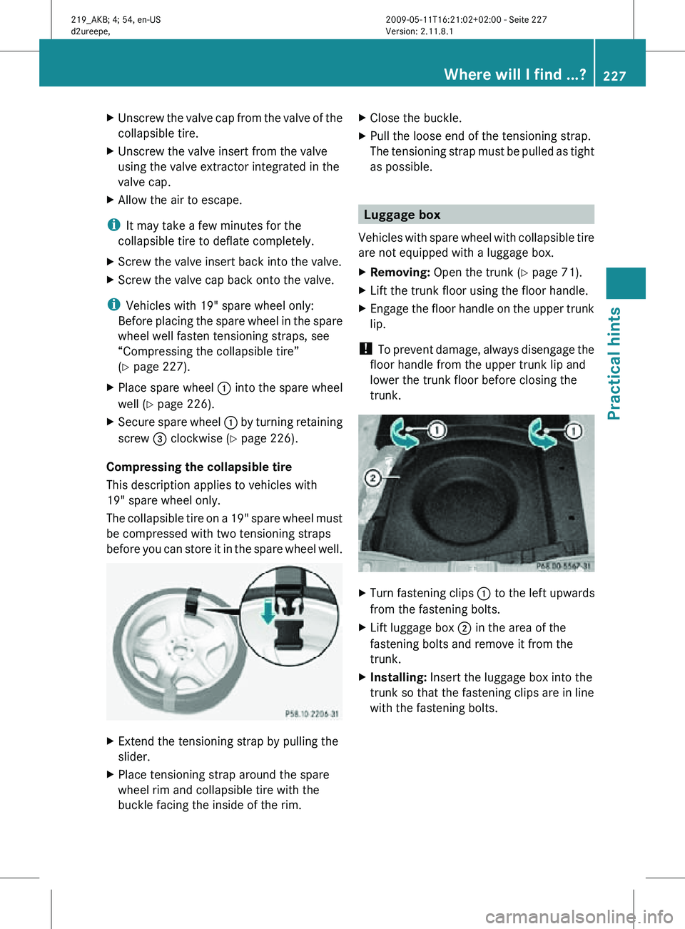
before you can store it in the spare wheel well. X
Extend the tensioning strap by pulling the
slider.
X Place tensioning strap around the spare
wheel rim and collapsible tire with the
buckle facing the inside of the rim. X
Close the buckle.
X Pull the loose end of the tensioning strap.
The tensioning strap must be pulled as tight
as possible. Luggage box
Vehicles with spare wheel with collapsible tire
are not equipped with a luggage box.
X Removing: Open the trunk (Y page 71).
X Lift the trunk floor using the floor handle.
X Engage the floor handle on the upper trunk
lip.
! To prevent damage, always disengage the
floor handle from the upper trunk lip and
lower the trunk floor before closing the
trunk. X
Turn fastening clips : to the left upwards
from the fastening bolts.
X Lift luggage box ; in the area of the
fastening bolts and remove it from the
trunk.
X Installing: Insert the luggage box into the
trunk so that the fastening clips are in line
with the fastening bolts. Where will I find ...?
227Practical hints
219_AKB; 4; 54, en-US
d2ureepe, Version: 2.11.8.1 2009-05-11T16:21:02+02:00 - Seite 227 Z
Page 230 of 308
X
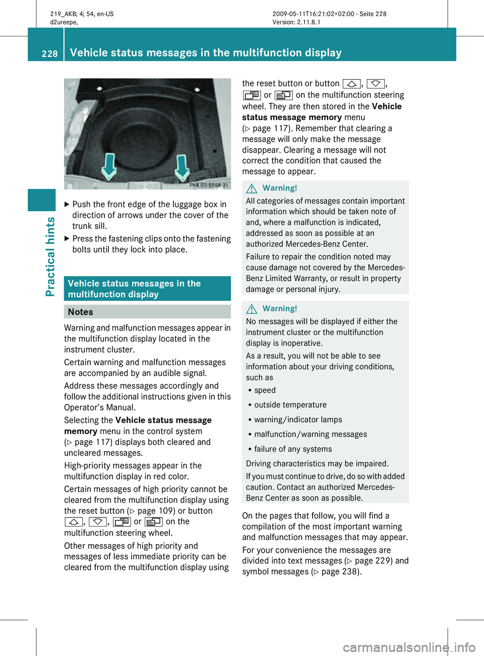
Push the front edge of the luggage box in
direction of arrows under the cover of the
trunk sill.
X Press the fastening clips onto the fastening
bolts until they lock into place. Vehicle status messages in the
multifunction display
Notes
Warning and malfunction messages appear in
the multifunction display located in the
instrument cluster.
Certain warning and malfunction messages
are accompanied by an audible signal.
Address these messages accordingly and
follow the additional instructions given in this
Operator’s Manual.
Selecting the Vehicle status message
memory menu in the control system
(Y page 117) displays both cleared and
uncleared messages.
High-priority messages appear in the
multifunction display in red color.
Certain messages of high priority cannot be
cleared from the multifunction display using
the reset button (Y page 109) or button
&, *, U or V on the
multifunction steering wheel.
Other messages of high priority and
messages of less immediate priority can be
cleared from the multifunction display using the reset button or button
&, *,
U or V on the multifunction steering
wheel. They are then stored in the Vehicle
status message memory menu
(Y page 117). Remember that clearing a
message will only make the message
disappear. Clearing a message will not
correct the condition that caused the
message to appear. G
Warning!
All categories of messages contain important
information which should be taken note of
and, where a malfunction is indicated,
addressed as soon as possible at an
authorized Mercedes-Benz Center.
Failure to repair the condition noted may
cause damage not covered by the Mercedes-
Benz Limited Warranty, or result in property
damage or personal injury. G
Warning!
No messages will be displayed if either the
instrument cluster or the multifunction
display is inoperative.
As a result, you will not be able to see
information about your driving conditions,
such as
R speed
R outside temperature
R warning/indicator lamps
R malfunction/warning messages
R failure of any systems
Driving characteristics may be impaired.
If you must continue to drive, do so with added
caution. Contact an authorized Mercedes-
Benz Center as soon as possible.
On the pages that follow, you will find a
compilation of the most important warning
and malfunction messages that may appear.
For your convenience the messages are
divided into text messages ( Y page 229) and
symbol messages ( Y page 238).228
Vehicle status messages in the multifunction displayPractical hints
219_AKB; 4; 54, en-US
d2ureepe,
Version: 2.11.8.1 2009-05-11T16:21:02+02:00 - Seite 228
Page 275 of 308
with the jack. Do not disengage the parking
brake while the vehicle is raised.
Make sure that the ground on which the
vehicle is standing and where you place the
jack is solid, level and not slippery. If
necessary, use a large underlay. On slippery
surfaces, such as tiled floors, you should use
a non-slip underlay, for example a rubber mat.
Do not use wooden blocks or similar objects
to support the jack. Otherwise the jack may
not be able to achieve its load-bearing
capacity if it is not at its full height.
Never start the engine when the vehicle is
raised.
Also observe the notes on the jack.
X Prevent the vehicle from rolling away by
blocking wheels with wheel chocks or other
sizeable objects.
When your vehicle is equipped with a wheel
chock, it is included with the vehicle tool kit
(Y page 224). For information on setting up
the collapsible wheel chock, see
(Y page 225).
When changing a wheel on a level surface:
X Place a wheel chock or other sizeable
object in front of and another wheel chock
or other sizeable object behind the wheel
that is diagonally opposite to the wheel
being changed.
Always try lifting the vehicle using the jack on
a level surface. However, should
circumstances require you to do so on a hill:
X Place wheel chocks or other sizeable
objects on the downhill side in front of both
wheels on the side opposite to the side on
which the wheel is to be changed. G
Warning!
Only jack up the vehicle on level ground or on
slight inclines/declines. Otherwise, the
vehicle could fall off the jack and injure you or
others. X
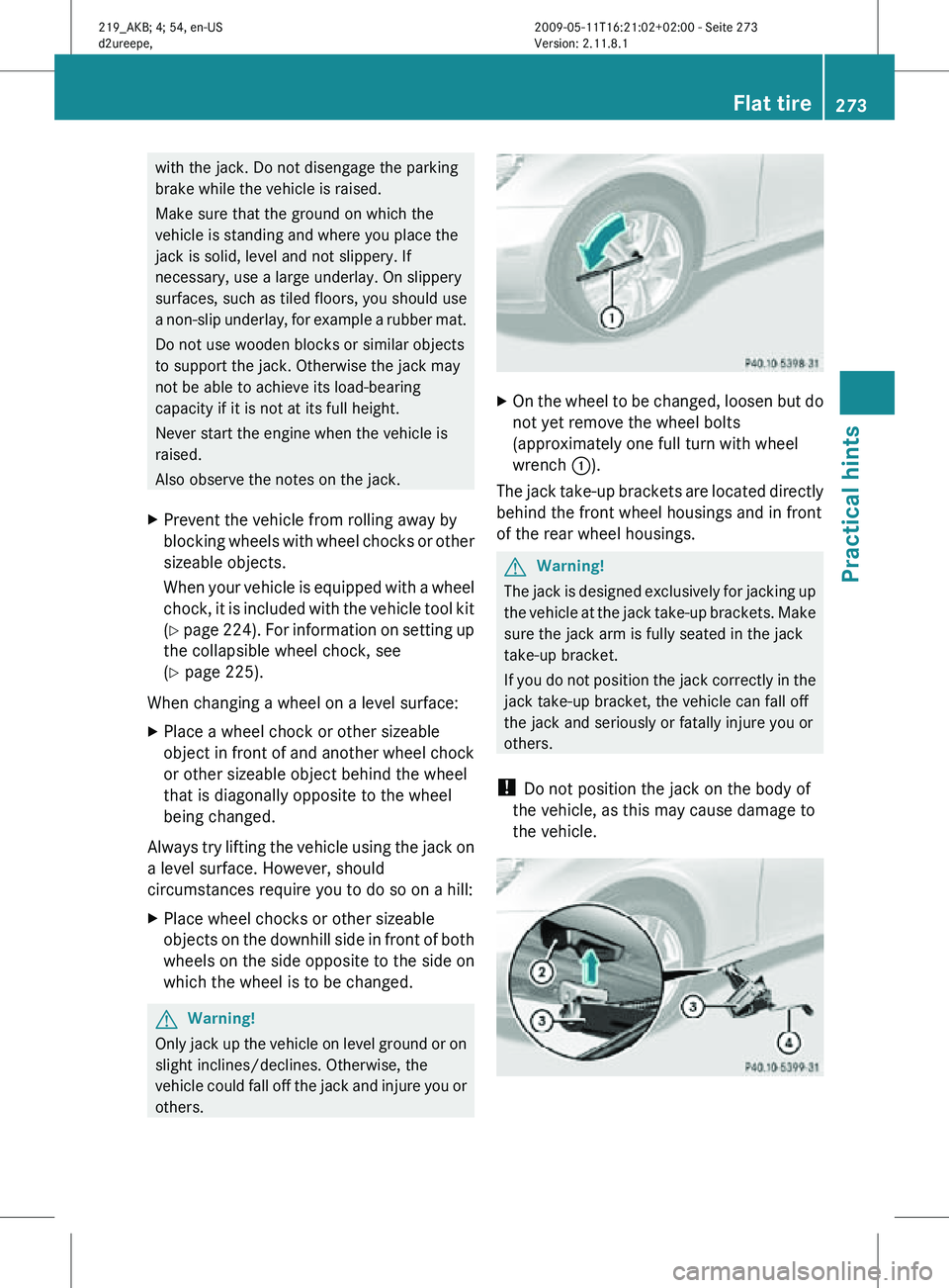
On the wheel to be changed, loosen but do
not yet remove the wheel bolts
(approximately one full turn with wheel
wrench :).
The jack take-up brackets are located directly
behind the front wheel housings and in front
of the rear wheel housings. G
Warning!
The jack is designed exclusively for jacking up
the vehicle at the jack take-up brackets. Make
sure the jack arm is fully seated in the jack
take-up bracket.
If you do not position the jack correctly in the
jack take-up bracket, the vehicle can fall off
the jack and seriously or fatally injure you or
others.
! Do not position the jack on the body of
the vehicle, as this may cause damage to
the vehicle. Flat tire
273Practical hints
219_AKB; 4; 54, en-US
d2ureepe, Version: 2.11.8.1 2009-05-11T16:21:02+02:00 - Seite 273 Z
Page 276 of 308
X
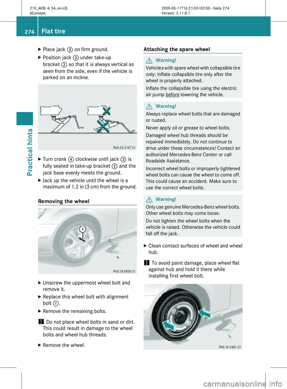
Place jack = on firm ground.
X Position jack = under take-up
bracket ; so that it is always vertical as
seen from the side, even if the vehicle is
parked on an incline. X
Turn crank ? clockwise until jack = is
fully seated in take-up bracket ; and the
jack base evenly meets the ground.
X Jack up the vehicle until the wheel is a
maximum of 1.2 in (3 cm) from the ground.
Removing the wheel X
Unscrew the uppermost wheel bolt and
remove it.
X Replace this wheel bolt with alignment
bolt :.
X Remove the remaining bolts.
! Do not place wheel bolts in sand or dirt.
This could result in damage to the wheel
bolts and wheel hub threads.
X Remove the wheel. Attaching the spare wheel G
Warning!
Vehicles with spare wheel with collapsible tire
only: Inflate collapsible tire only after the
wheel is properly attached.
Inflate the collapsible tire using the electric
air pump before lowering the vehicle.
G
Warning!
Always replace wheel bolts that are damaged
or rusted.
Never apply oil or grease to wheel bolts.
Damaged wheel hub threads should be
repaired immediately. Do not continue to
drive under these circumstances! Contact an
authorized Mercedes-Benz Center or call
Roadside Assistance.
Incorrect wheel bolts or improperly tightened
wheel bolts can cause the wheel to come off.
This could cause an accident. Make sure to
use the correct wheel bolts. G
Warning!
Only use genuine Mercedes-Benz wheel bolts.
Other wheel bolts may come loose.
Do not tighten the wheel bolts when the
vehicle is raised. Otherwise the vehicle could
fall off the jack.
X Clean contact surfaces of wheel and wheel
hub.
! To avoid paint damage, place wheel flat
against hub and hold it there while
installing first wheel bolt. 274
Flat tirePractical hints
219_AKB; 4; 54, en-US
d2ureepe,
Version: 2.11.8.1 2009-05-11T16:21:02+02:00 - Seite 274
Page 277 of 308
X
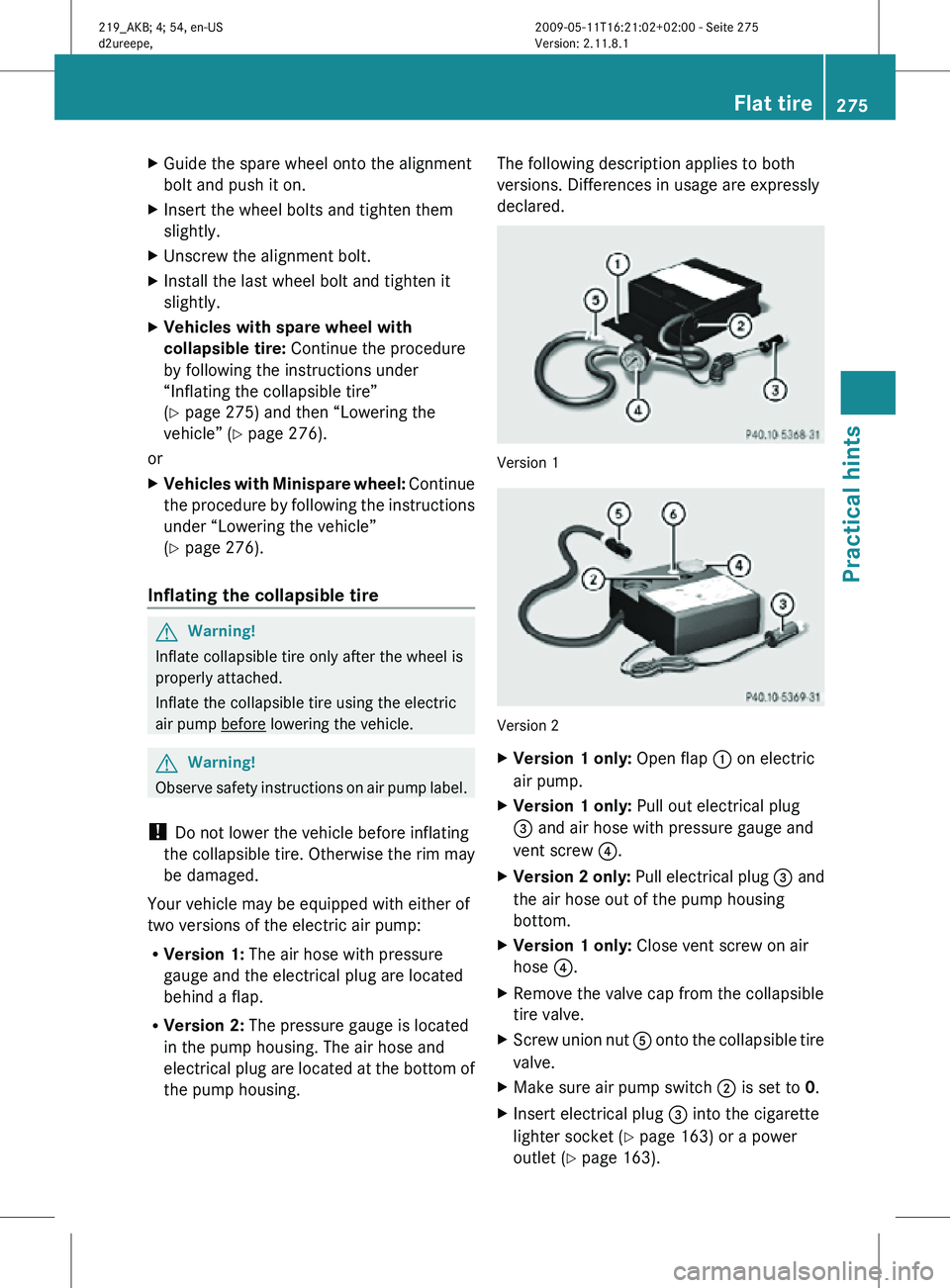
Guide the spare wheel onto the alignment
bolt and push it on.
X Insert the wheel bolts and tighten them
slightly.
X Unscrew the alignment bolt.
X Install the last wheel bolt and tighten it
slightly.
X Vehicles with spare wheel with
collapsible tire: Continue the procedure
by following the instructions under
“Inflating the collapsible tire”
(Y page 275) and then “Lowering the
vehicle” ( Y page 276).
or
X Vehicles with Minispare wheel: Continue
the procedure by following the instructions
under “Lowering the vehicle”
(Y page 276).
Inflating the collapsible tire G
Warning!
Inflate collapsible tire only after the wheel is
properly attached.
Inflate the collapsible tire using the electric
air pump before lowering the vehicle.
G
Warning!
Observe safety instructions on air pump label.
! Do not lower the vehicle before inflating
the collapsible tire. Otherwise the rim may
be damaged.
Your vehicle may be equipped with either of
two versions of the electric air pump:
R Version 1: The air hose with pressure
gauge and the electrical plug are located
behind a flap.
R Version 2: The pressure gauge is located
in the pump housing. The air hose and
electrical plug are located at the bottom of
the pump housing. The following description applies to both
versions. Differences in usage are expressly
declared.
Version 1
Version 2
X
Version 1 only: Open flap : on electric
air pump.
X Version 1 only: Pull out electrical plug
= and air hose with pressure gauge and
vent screw ?.
X Version 2 only: Pull electrical plug = and
the air hose out of the pump housing
bottom.
X Version 1 only: Close vent screw on air
hose ?.
X Remove the valve cap from the collapsible
tire valve.
X Screw union nut A onto the collapsible tire
valve.
X Make sure air pump switch ; is set to 0.
X Insert electrical plug = into the cigarette
lighter socket ( Y page 163) or a power
outlet (Y page 163). Flat tire
275Practical hints
219_AKB; 4; 54, en-US
d2ureepe, Version: 2.11.8.1 2009-05-11T16:21:02+02:00 - Seite 275 Z
Page 279 of 308
X
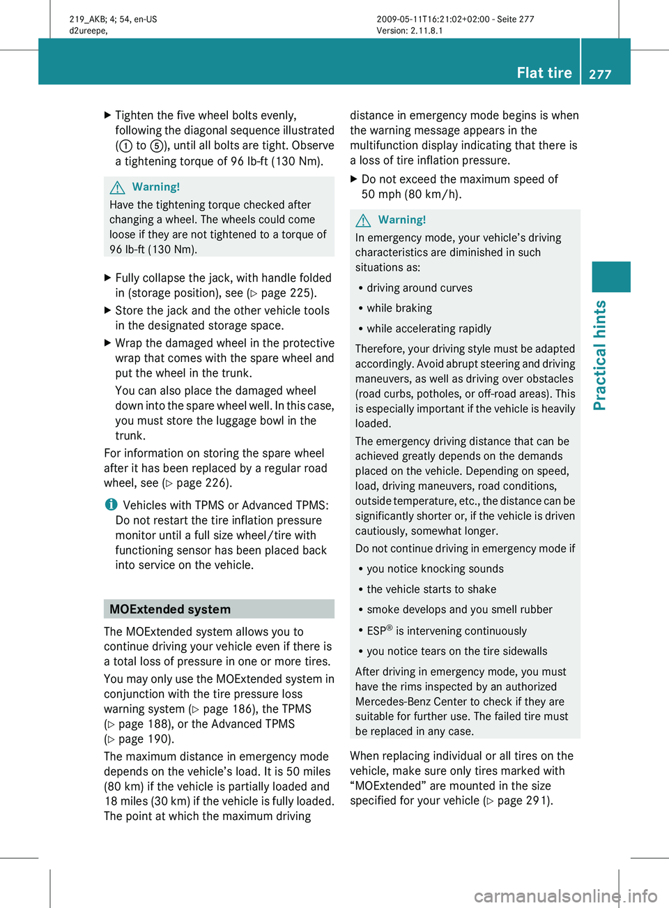
Tighten the five wheel bolts evenly,
following
the diagonal sequence illustrated
(: to A), until all bolts are tight. Observe
a tightening torque of 96 lb-ft (130 Nm). G
Warning!
Have the tightening torque checked after
changing a wheel. The wheels could come
loose if they are not tightened to a torque of
96 lb-ft (130 Nm).
X Fully collapse the jack, with handle folded
in (storage position), see
(Y page 225).
X Store the jack and the other vehicle tools
in the designated storage space.
X Wrap the damaged wheel in the protective
wrap
that comes with the spare wheel and
put the wheel in the trunk.
You can also place the damaged wheel
down into the spare wheel well. In this case,
you must store the luggage bowl in the
trunk.
For information on storing the spare wheel
after it has been replaced by a regular road
wheel, see
(Y page 226).
i Vehicles with TPMS or Advanced TPMS:
Do not restart the tire inflation pressure
monitor until a full size wheel/tire with
functioning sensor has been placed back
into service on the vehicle. MOExtended system
The MOExtended system allows you to
continue driving your vehicle even if there is
a total loss of pressure in one or more tires.
You
may only use the MOExtended system in
conjunction with the tire pressure loss
warning system ( Y page 186), the TPMS
(Y page 188), or the Advanced TPMS
(Y page 190).
The maximum distance in emergency mode
depends on the vehicle’s load. It is 50 miles
(80 km) if the vehicle is partially loaded and
18 miles (30 km) if the vehicle is fully loaded.
The point at which the maximum driving distance in emergency mode begins is when
the warning message appears in the
multifunction display indicating that there is
a loss of tire inflation pressure.
X
Do not exceed the maximum speed of
50 mph (80 km/h
). G
Warning!
In emergency mode, your vehicle’s driving
characteristics are diminished in such
situations as:
R driving around curves
R while braking
R while accelerating rapidly
Therefore,
your driving style must be adapted
accordingly. Avoid abrupt steering and driving
maneuvers, as well as driving over obstacles
(road curbs, potholes, or off-road areas). This
is especially important if the vehicle is heavily
loaded.
The emergency driving distance that can be
achieved greatly depends on the demands
placed on the vehicle. Depending on speed,
load, driving maneuvers, road conditions,
outside temperature, etc., the distance can be
significantly shorter or, if the vehicle is driven
cautiously, somewhat longer.
Do not continue driving in emergency mode if
R you notice knocking sounds
R the vehicle starts to shake
R smoke develops and you smell rubber
R ESP ®
is intervening continuously
R you notice tears on the tire sidewalls
After driving in emergency mode, you must
have the rims inspected by an authorized
Mercedes-Benz Center to check if they are
suitable for further use. The failed tire must
be replaced in any case.
When replacing individual or all tires on the
vehicle, make sure only tires marked with
“MOExtended” are mounted in the size
specified for your vehicle ( Y page 291). Flat tire
277
Practical hints
219_AKB; 4; 54, en-US
d2ureepe, Version: 2.11.8.1 2009-05-11T16:21:02+02:00 - Seite 277 Z