spare tire MERCEDES-BENZ CLS 2018 Owners Manual
[x] Cancel search | Manufacturer: MERCEDES-BENZ, Model Year: 2018, Model line: CLS, Model: MERCEDES-BENZ CLS 2018Pages: 334, PDF Size: 7.87 MB
Page 5 of 334
Care .................................................... .2 70
Breakdown assistance ..................... 277
Where will I find...? .............................. 277
Flat tire ................................................ 278
Battery (vehicle) .................................. 282
Jump-starting ....................................... 285
Towing and tow-starting ..................... .2 87
Fuses ................................................... 290
Wheels and tires ............................... 292
Important safety notes ........................ 292
Operation ............................................ 292
Winter operation .................................. 294
Tire pressure ....................................... 295
Loading the vehicle .............................. 302
All about wheels and tires ................... 305
Changing a wheel ................................ 312
Wheel and tire combinations .............. .3 17
Emergency spare wheel ....................... 317
Technical data ................................... 321
Information regarding technical data ... 321
Vehicle electronics .............................. 321
Identification plates ............................ .3 22
Service products and filling capaci-
ties ...................................................... 323
Vehicle data ......................................... 328 Contents 3
Page 13 of 334
Exhaust check .................................. .1 44
Exhaust pipe (cleaning instruc-
tions) ................................................. .2 74
Exterior lighting
Setting options .............................. 105
see Lights
Exterior mirrors
Adjusting ....................................... 101
Dipping (automatic) ....................... 102
Folding in when locking (on-board
computer) ...................................... 200
Folding in/out (automatically) ....... 102
Folding in/out (electrically) ........... 101
Out of position (troubleshooting) ... 102
Setting ........................................... 101
Storing settings (memory func-
tion) ............................................... 104
Storing the parking position .......... 102
Eyeglasses compartment ................. 243
F Favorites
Overview ........................................ 238
Filler cap
see Refueling
Flat tire
MOExtended tires .......................... 278
Preparing the vehicle ..................... 278
TIREFIT kit ...................................... 279
see Emergency spare wheel
Floormats ........................................... 264
Frequencies
Mobile phone ................................. 321
Two-way radio ................................ 321
Fuel
Additives ........................................ 325
Consumption statistics .................. 191
Displaying the current consump-
tion ................................................ 191
Displaying the range ...................... 191
Driving tips .................................... 143
Fuel gauge ....................................... 34
Grade (gasoline) ............................ 324
Important safety notes .................. 324
Notes for CLS 400, CLS 400
4MATIC .......................................... 325
Problem (malfunction) ................... 140 Refueling ........................................ 138
Tank content/reserve fuel ............. 324
Fuel filler flap
Emergency release ........................ 140
Opening ......................................... 139
Fuel level
Calling up the range (on-board
computer) ...................................... 191
Fuel tank
Capacity ........................................ 324
Problem (malfunction) ................... 140
Fuse allocation chart (vehicle tool
kit) ...................................................... 277
Fuses
Allocation chart ............................. 290
Before changing ............................. 290
Fuse box in the engine compart-
ment .............................................. 291
Fuse box in the trunk ..................... 291
Important safety notes .................. 290
G Garage door opener
Clearing the memory ..................... 263
General notes ................................ 261
Important safety notes .................. 261
Opening/closing the garage doo r. .2 63
Problems when programming ....... .2 63
Programming (button in the rear-
view mirror) ................................... 261
Synchronizing the rolling code ....... 262
Gasoline ............................................. 324
Gear indicator (on-board com-
puter, Mercedes-AMG vehicles) ....... 201
Genuine parts ...................................... 25
Glove box .......................................... .2 43
Google™ Local Search
see also Digital Operator's Man-
ual .................................................. 236
H
Handbrake
see Parking brake
Hazard warning lamps ...................... 107
Head bags
Display message ............................ 209 Index 11
Page 21 of 334
Warning lamp ................................. 231
Standing lamps
Display message ........................... .2 12
Switching on/off ........................... 106
Start/stop function
see ECO start/stop function
Starting (engine) ................................ 124
Steering
Display message ............................ 225
Steering Assist and Stop&Go Pilot
(DISTRONIC PLUS)
Activating/deactivating ................. 196
Display message ............................ 220
Steering wheel
Adjusting (electrically) ..................... 99
Button overview ............................... 35
Buttons (on-board computer) ......... 189
Cleaning ......................................... 275
Important safety notes .................... 98
Paddle shifters ............................... 135
Steering wheel heating .................... 99
Storing settings (memory func-
tion) ............................................... 104
Steering wheel heating
Problem (malfunction) ..................... 99
Switching on/off .............................. 99
Steering wheel paddle shifters ....... .1 35
Stopwatch (RACETIMER) ................... 201
Stowage areas ................................... 242
Stowage compartments
Armrest (under) ............................ .2 44
Center console .............................. 243
Center console (rear) ..................... 244
Cup holders ................................... 248
Eyeglasses compartment .............. .2 43
Glove box ....................................... 243
Important safety information ......... 242
Rear ............................................... 244
Stowage net ................................... 245
Under driver's seat/front-
passenger seat .............................. 244
Stowage net ....................................... 245
Stowage well beneath the trunk
floor .................................................... 247
Summer tires ..................................... 294
Sun visor ............................................ 250 Surround lighting (on-board com-
puter) .................................................. 198
Suspension setting
AIRMATIC ...................................... 160
AMG adaptive sport suspension
system ........................................... 161
Sus pens ion settings
SET
UP (on-board computer) .......... 201
Switching air-recirculation mode
on/off ................................................. 120
Switching on media mode
Via the device list .......................... 241
T Tachometer ........................................ 188
Tail lamps
Display message ............................ 212
Tank
see Fuel tank
Tank content
Fuel gauge ....................................... 34
Technical data
Capacities ...................................... 323
Emergency spare wheel ................. 318
Information .................................... 321
Tires/wheels ................................. 317
Vehicle data ................................... 328
Telephone
Accepting a call (multifunction
steering wheel) .............................. 194
Authorizing a mobile phone (con-
necting) ......................................... 240
Connecting a mobile phone (gen-
eral information) ............................ 239
Display message ............................ 225
Menu (on-board computer) ............ 194
Number from the phone book ........ 194
Redialing ........................................ 195
Rejecting/ending a call ................. 194
see also Digital Operator's Man-
ual .................................................. 236
Switching between mobile
phones ........................................... 241
Temperature
Coolant .......................................... 188
Coolant (on-board computer,
Mercedes-AMG vehicles) ............... 201 Index 19
Page 24 of 334
Data acquisition ............................... 30
Display message ............................ 223
Equipment ....................................... 26
Individual settings .......................... 197
Limited Warranty ............................. 30
Loading .......................................... 302
Locking (in an emergency) ............... 83
Locking (SmartKey) .......................... 76
Lowering ........................................ 316
Maintenance .................................... 27
Parking for a long period ................ 143
Pulling away ................................... 125
Raising ........................................... 313
Reporting problems ........................ .2 9
Securing from rolling away ............ 313
Towing away .................................. 287
Transporting .................................. 289
Unlocking (in an emergency) ........... 83
Unlocking (SmartKey) ...................... 76
Vehicle data ................................... 328
Vehicle data ....................................... 328
Vehicle dimensions ........................... 328
Vehicle emergency locking ................ 83
Vehicle identification number
see VIN
Vehicle identification plate .............. 322
Vehicle level
AIRMATIC ...................................... 159
Vehicle level (display message) ....... 215
Vehicle tool kit .................................. 277
Video
Operating the DVD ......................... 193
see also Digital Operator's Man-
ual .................................................. 236
VIN
Seat ............................................... 323
Type plate ...................................... 322
Voice Control System
see See also Digital Operator's Manual
W
Warning and indicator lamps
ABS ................................................ 229
Brakes ........................................... 228
Check Engine ................................. 232
Coolant .......................................... 232
Distance warning ........................... 234 ESP ®
.............................................. 229
ESP ®
OFF ....................................... 230
Fuel tank ........................................ 232
General notes ................................ 226
Overview .......................................... 34
PASSENGER AIR BAG OFF ............... 42
Reserve fuel ................................... 232
Restraint system ............................ 231
Seat belt ........................................ 227
SPORT handling mode ................... 231
Tire pressure monitor .................... 235
Warranty .............................................. 26
Washer fluid
Display message ............................ 225
Weather display (COMAND)
see also Digital Operator's Man-
ual .................................................. 236
Wheel and tire combinations
Tires ............................................... 317
Wheel bolt tightening torque ........... 316
Wheel chock ...................................... 313
Wheels
Changing a wheel .......................... 312
Checking ........................................ 292
Cleaning ......................................... 273
Emergency spare wheel ................. 317
Important safety notes .................. 292
Information on driving .................... 292
Interchanging/changing ................ 312
Mounting a new wheel ................... 315
Mounting a wheel .......................... 313
Removing a wheel .......................... 315
Storing ........................................... 313
Tightening torque ........................... 316
Wheel size/tire size ....................... 317
Window curtain air bag
Operation ......................................... 49
Windows
see Side windows
Windshield
Defrosting ...................................... 118
Windshield washer fluid
see Windshield washer system
Windshield washer system
Adding washer fluid ....................... 269
Important safety notes .................. 32722
Index
Page 280 of 334
i Example: equipment and country-specific
variations possible.
Vehicles with alloy wheels and hub caps On vehicles with alloy wheels and hub caps, a
socket is also provided.
Flat tire
Preparing the vehicle Your vehicle may be equipped with: R
MOExtended tires (tires with run-flat proper-
ties) ( Y
page 278)
Vehicle preparation is not necessary on vehi-
cles with MOExtended tires R
a TIREFIT kit ( Y
page 277)R
an emergency spare wheel ( Y
page 317)
Vehicles equipped with MOExtended tires are
not equipped with a TIREFIT kit at the factory. It
is therefore recommended that you additionally
equip your vehicle with a TIREFIT kit if you mount
tires that do not feature run-flat properties, e.g.
winter tires. A TIREFIT kit may be obtained from
a qualified specialist workshop.
Information on changing and mounting wheels
( Y
page 312). X
Stop the vehicle on solid, non-slippery and
level ground, as far away as possible from
traffic. X
Switch on the hazard warning lamps. X
Secure the vehicle against rolling away
( Y
page 141).X
If possible, bring the front wheels into the
straight-ahead position. X
Vehicles with AIRMATIC: make sure that "nor-
mal" level is selected ( Y
page 159).X
Switch off the engine. X
Remove the SmartKey from the ignition lock.
or, on vehicles with KEYLESS ‑ GO:X
Open the driver's door.
T he vehicle electronics now have status 0 .
This is the same as the SmartKey having been
removed. X
Remove the Start/Stop button from the igni-
tion lock ( Y
page 123).X
Make sure that the passengers are not endan-
gered as they do so. Make sure that no one is
near the danger area while a wheel is being changed. Anyone who is not directly assisting
in the wheel change should, for example,
stand behind the barrier. X
Get out of the vehicle. Pay attention to traffic
conditions when doing so. X
Close the driver's door.
MOExtended tires (tires with run-flat
properties)
General notes With MOExtended tires (tires with run flat char-
acteristics), you can continue to drive your vehi-
cle even if there is a total loss of pressure in one
or more tires. The affected tire must not show
any clearly visible damage.
You can recognize MOExtended tires by the
MOExtended marking which appears on the
sidewall of the tire. You will find this marking
next to the tire size designation, the load-bear-
ing capacity and the speed index ( Y
page 307).
MOExtended tires may only be used in conjunc-
tion with an active tire pressure loss warning
system or with an active tire pressure monitor.
If a pressure loss warning message appears
in the multifunction display: R
observe the instructions in the display mes-
sages ( Y
page 221). R
check the tire for damage. R
if driving on, observe the following notes.
The driving distance possible in run-flat mode is
approximately 50 miles (80 km) when the vehi-
cle is partially laden. When the vehicle is fully
laden it is approximately 19 miles (30 km).
In addition to the vehicle load, the driving dis-
tance possible depends upon: R
Vehicle speed R
Road condition R
Outside temperature
The driving distance p ossible in run-flat mode
may be reduced by extreme driving conditions
or maneuvers, or it can be increased through a
moderate style of driving.
The driving distance possible in run-flat mode is
counted from the moment the tire pressure loss
warning appears in the multifunction display.
You must not exceed a maximum permissible
speed of 50 mph (80 km/h).278
Flat tire
Breakdown assistance
Page 295 of 334
off-road or on rough roads. Damaged wheels
can cause a loss of tire pressure.
Pay particular attention to damage such as: R
cuts in the tires R
punctures in the tires R
tears in the tires R
bulges on tires R
deformation or severe corrosion on wheels
Regularly check the tire tread depth and the
condition of the tread across the whole width of
the tire ( Y
page 293). If necessary, turn the
front wheels to full lock in order to inspect the
inner side of the tire surface.
All wheels must have a valve cap to protect the
valve against dirt and moisture. Do not mount
anything onto the valve other than the standard
valve cap or other valve caps approved by
Mercedes-Benz for your vehicle. Do not use any
other valve caps or systems, e.g. tire pressure
monitoring systems.
Regularly check the pressure of all the tires par-
ticularly prior to long trips. Adjust the tire pres-
sure as necessary ( Y
page 295).
Observe the notes on the emergency spare
wheel ( Y
page 317).
The service life of tires depends, among other
things, on the following factors: R
Driving style R
Tire pressure R
Distance covered
Notes on tire tread
G WARNING
Insufficient tire tread will reduce tire traction.
The tire is no longer able to dissipate water.
This means that on wet road surfaces, the risk
of hydroplaning increases, in particular where
speed is not adapted to suit the driving con-
ditions. There is a risk of accident.
If the tire pressure is too high or too low, tires
may exhibit different levels of wear at differ-
ent locations on the tire tread. Thus, you
should regularly check the tread depth and
the condition of the tread across the entire
width of all tires. Minimum tire tread depth for: R
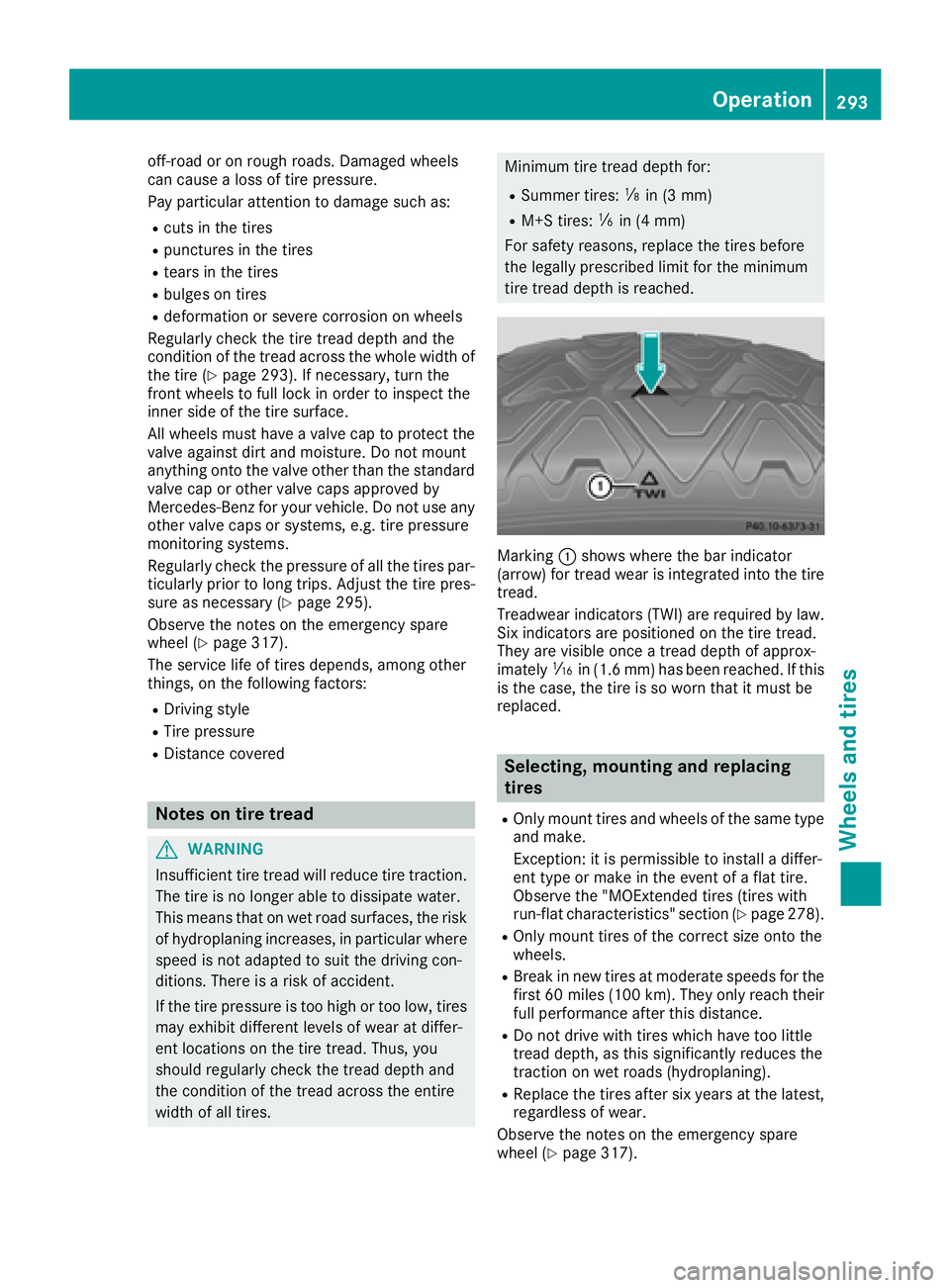
Summer tires: �
Page 297 of 334
To avoid hazardous situations: R
never install snow chains to the front
wheels R
always install snow chains in pairs to the
rear wheels.
! On vehicles with AIRMATIC, you must drive
at raised vehicle level if snow chains have
been mounted. The vehicle may otherwise be
damaged.
! On some tire sizes there is not enough space
for snow chains. To avoid damage to the vehi-
cle or tires, observe the "Wheel and tire com-
binations" section under "Tires and wheels".
For safety reasons, Mercedes-Benz recom-
mends that you only use snow chains that have
been specially approved for your vehicle by
Mercedes-Benz, or are of a corresponding
standard of quality. For more information, con-
tact a qualified specialist workshop.
If you intend to mount snow chains, please bear
the following points in mind: R
Snow chains may not be mounted on all
wheel/tire combinations. Permissible
wheel/tire combinations ( Y
page 317).R
Only use snow chains when driving on roads
completely covered by snow. Remove the
snow chains as soon as possible when you
come to a road that is not snow-covered. R
Local regulations may restrict the use of snow
chains. Observe the appropriate regulations if
you wish to mount snow chains. R
Do not exceed the maximum permissible
speed of 31 mph (50 km/h).
i You may wish to deactivate ESP ®
when pull-
ing away with snow chains installed: R
All vehicles (except Mercedes ‑ AMG vehi-
cles) ( Y
page 70)R
Mercedes-AMG vehicles: ( Y
page 71)
You can thereby allow the wheels to spin in a
controlled manner, achieving an increased
driving force (cutting action).
Information about driving with an emergency
spare wheel ( Y
page 317). Tire pressure
Tire pressure specifications
Important safety notes
G WARNING
Underinflated or overinflated tires pose the
following risks: R
the tires may burst, especially as the load
and vehicle speed increase. R
the tires may wear excessively and/or
unevenly, which may greatly impair tire
traction. R
the driving characteristics, as well as steer-
ing and braking, may be greatly impaired.
There is a risk of an accident.
Follow recommended tire inflation pressures
and check the pressure of all the tires includ-
ing the spare wheel: R
monthly, at least R
if the load changes R
before beginning a long journey R
under different operating conditions, e.g.
off-road driving
If necessary, correct the tire pressure.
The data on the Tire and Loading Information
placard and tire pressure table shown here are
examples. Tire pressure specifications are vehi-
cle-specific and may deviate from the data
shown here. The tire pressure specifications
that are valid for your vehicle can be found on
the Tire and Loading Information placard and
tire pressure table on the vehicle.
General notes The recommended tire pressures for the tires
mounted at the factory can be found on the
labels described here.
Operation with an emergency spare wheel:
information on operation with an emergency
spare wheel can be found in the general notes in
the "Emergency spare wheel" section
( Y
page 318).
Further information on tire pressures can be
obtained at a qualified specialist workshop. Tire pressure 295
Wheels and tires Z
Page 302 of 334
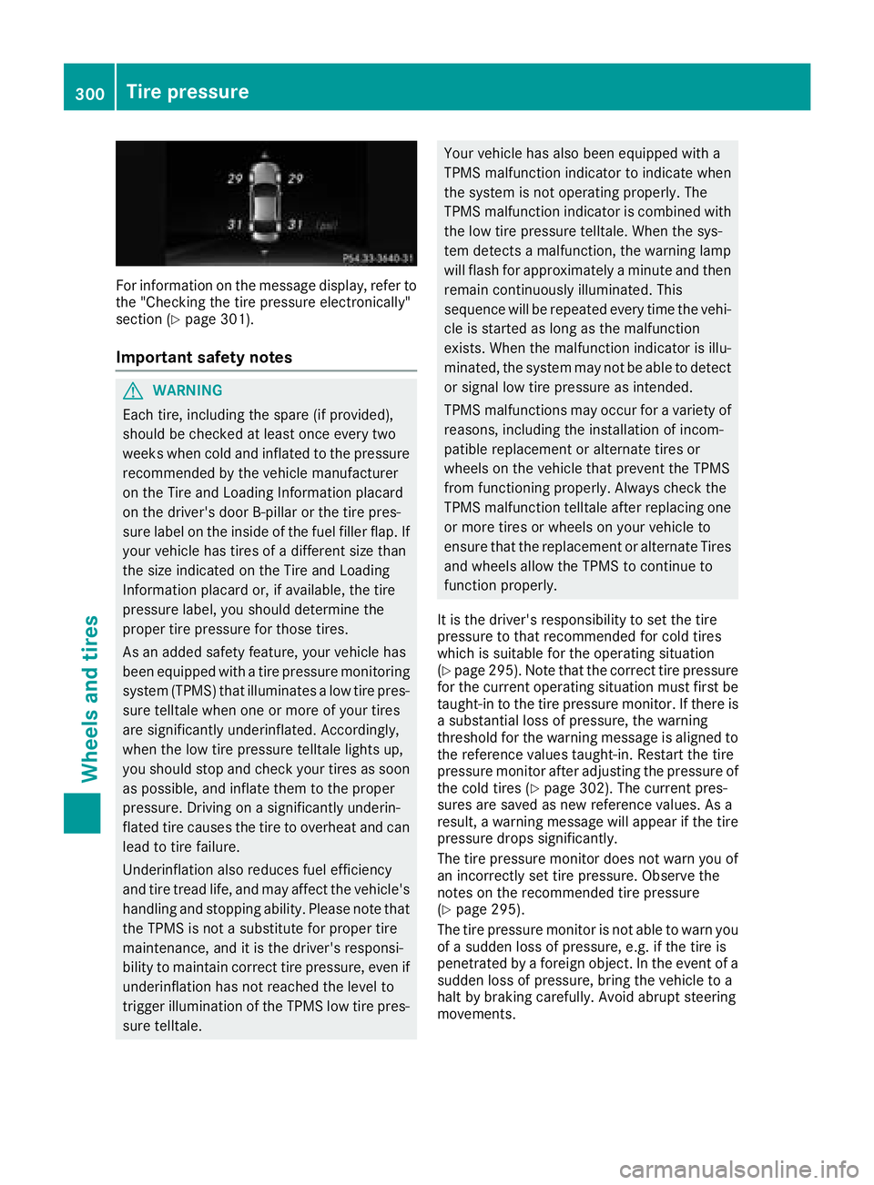
For information on the message display, refer to
the "Checking the tire pressure electronically"
section ( Y
page 301).
Important safety notes
G WARNING
Each tire, including the spare (if provided),
should be checked at least once every two
weeks when cold and inflated to the pressure
recommended by the vehicle manufacturer
on the Tire and Loading Information placard
on the driver's door B-pillar or the tire pres-
sure label on the inside of the fuel filler flap. If
your vehicle has tires of a different size than
the size indicated on the Tire and Loading
Information placard or, if available, the tire
pressure label, you should determine the
proper tire pressure for those tires.
As an added safety feature, your vehicle has
been equipped with a tire pressure monitoring
system (TPMS) that illuminates a low tire pres-
sure telltale when one or more of your tires
are significantly underinflated. Accordingly,
when the low tire pressure telltale lights up,
you should stop and check your tires as soon
as possible, and inflate them to the proper
pressure. Driving on a significantly underin-
flated tire causes the tire to overheat and can
lead to tire failure.
Underinflation also reduces fuel efficiency
and tire tread life, and may affect the vehicle's
handling and stopping ability. Please note that
the TPMS is not a substitute for proper tire
maintenance, and it is the driver's responsi-
bility to maintain correct tire pressure, even if
underinflation has not reached the level to
trigger illumination of the TPMS low tire pres-
sure telltale. Your vehicle has also been equipped with a
TPMS malfunction indicator to indicate when
the system is not operating properly. The
TPMS malfunction indicator is combined with
the low tire pressure telltale. When the sys-
tem detects a malfunction, the warning lamp
will flash for approximately a minute and then
remain continuously illuminated. This
sequence will be repeated every time the vehi-
cle is started as long as the malfunction
exists. When the malfunction indicator is illu-
minated, the system may not be able to detect
or signal low tire pressure as intended.
TPMS malfunctions may occur for a variety of
reasons, including the installation of incom-
patible replacement or alternate tires or
wheels on the vehicle that prevent the TPMS
from functioning properly. Always check the
TPMS malfunction telltale after replacing one
or more tires or wheels on your vehicle to
ensure that the replacement or alternate Tires
and wheels allow the TPMS to continue to
function properly.
It is the driver's responsibility to set the tire
pressure to that recommended for cold tires
which is suitable for the operating situation
( Y
page 295). Note that the correct tire pressure
for the current operating situation must first be
taught-in to the tire pressure monitor. If there is
a substantial loss of pressure, the warning
threshold for the warning message is aligned to
the reference values taught-in. Restart the tire
pre ssure moni tor after adjusting the pressure of
the
cold tires ( Y
page 302). The current pres-
sures are saved as new reference values. As a
result, a warning message will appear if the tire
pressure drops significantly.
The tire pressure monitor does not warn you of
an incorrectly set tire pressure. Observe the
notes on the recommended tire pressure
( Y
page 295).
The tire pressure monitor is not able to warn you
of a sudden loss of pressure, e.g. if the tire is
penetrated by a foreign object. In the event of a
sudden loss of pressure, bring the vehicle to a
halt by braking carefully. Avoid abrupt steering
movements.300
Tire pressure
Wheels and tires
Page 303 of 334
The tire pressure monitor has a yellow warning
lamp in the instrument cluster for indicating
pressure loss or a malfunction. Whether the
warning lamp flashes or lights up indicates
whether a tire pressure is too low or the tire
pressure monitor is malfunctioning: R
if the warning lamp is lit continuously, the tire
pressure on one or more tires is significantly
too low. The tire pressure monitor is not mal-
functioning. R
if the warning lamp flashes for around a
minute and then remains lit constantly, the
tire pressure monitor is malfunctioning.
In addition to the warning lamp, a message
appears in the multifunction display. Observe
the information on display messages
( Y
page 221).
It may take up to ten minutes for a malfunction
of the tire pressure monitor to be indicated. A
malfunction will be indicated by the tire pres-
sure warning lamp flashing for approximately
one minute and then remaining lit. When the
malfunction has been rectified, the tire pressure
warning lamp goes out after a few minutes of
driving.
The tire pressure values indicated by the on-
board computer may differ from those meas-
ured at a gas station with a pressure gauge. The
tire pressures shown by the on-board computer
refer to those measured at sea level. At high
altitudes, the tire pressure values indicated by a
pressure gauge are higher than those shown by
the on-board computer. In this case, do not
reduce the tire pressures.
The operation of the tire pressure monitor can
be affected by interference from radio transmit-
ting equipment (e.g. radio headphones, two-way
radios) that may be being operated in or near the
vehicle.
Checking the tire pressure electroni-
cally X
Make sure that the SmartKey is in position 2
in the ignition lock ( Y
page 123).X
Press the �Y or �e button on the steering
wheel to select the Service menu.X
Press the �c or �d button to select
Tire Pressure .X
Press the �v button.
The current tire pressure of each tire is shown
in the multifunction display. If the vehicle has been parked for over
20 minutes, the Tire pressures will be
displayed after driving a few minutes
message appears.
After a teach-in process, the tire pressure mon-
itor automatically detects new wheels or new
sensors. As long as a clear allocation of the tire
pressure value to the individual wheels is not
possible, the Tire Pressure Monitor Active
display message is shown instead of the tire
pressure display. The tire pressures are already
being monitored.
If an emergency spare wheel is mounted, the
system may continue to show the tire pressure
of the wheel that has been removed for a few
minutes. If this occurs, note that the value dis-
played for the position where the spare wheel is
mounted is not the same as the current tire
pressure of the emergency spare wheel.
Tire pressure monitor warning mes-
sages If the tire pressure monitor detects a pressure
loss in one or more tires, a warning message is
shown in the multifunction display. The yellow
tire pressure warning lamp then lights up. R
If the Correct Tire Pressure message
appears in the multifunction display, the tire
pressure in at least one tire is too low. The tire
pressure must be corrected when the oppor-
tunity arises. R
If the Check Tires message appears in the
multifunction display, the tire pressure in one
or more tires has dropped significantly. The
tires must be checked. R
If the Warning Tire Malfunction message
appears in the multifunction display, the tire
pressure in one or more tires is dropping sud-
denly. The tires must be checked.
Observe the instructions and safety notes in the
display messages in the "Tires" section
( Y
page 221).
If the wheel positions on the vehicle are rotated,
the tire pressures may be displayed for the
wrong positions for a short time. This is rectified
after a few minutes of driving, and the tire pres-
sures are displayed for the correct positions. Tire pressure 301
Wheels and tires Z
Page 313 of 334
Speed rating The speed rating is part of the tire identification.
It specifies the speed range for which the tire is
approved.
GVW (Gross Vehicle Weight) The gross vehicle weight includes the weight of
the vehicle including fuel, tools, the spare wheel,
accessories installed, occupants, luggage and
the drawbar noseweight, if applicable. The gross
vehicle weight must not exceed the gross vehi-
cle weight rating GVWR as specified on the vehi-
cle identification plate on the B-pillar on the
driver's side.
GVWR (Gross Vehicle Weight Rating) The GVWR is the maximum permissible gross
weight of a fully loaded vehicle (the weight of the
vehicle including all accessories, occupants,
fuel, luggage and the drawbar noseweight, if
applicable). The gross vehicle weight rating is
specified on the vehicle identification plate on
the B-pillar on the driver's side.
Maximum loaded vehicle weight The maximum weight is the sum of: R
the curb weight of the vehicle R
the weight of the accessories R
the load limit R
the weight of the factory installed optional
equipment
Kilopascal (kPa) Metric unit for tire pressure. 6.9 kPa corre-
sponds to 1 psi. Another unit for tire pressure is
bar. 100 kilopascals (kPa) are the equivalent of
1 bar.
Load index
In addition to the load-bearing index, the load
index may also be imprinted on the sidewall of
the tire. This specifies the load-bearing capacity
more precisely.
Curb weight
The weight of a vehicle with standard equipment
including the maximum capacity of fuel, oil and
coolant. It also includes the air-conditioning sys-
tem and optional equipment if these are instal-
led in the vehicle, but does not include passen-
gers or luggage. Maximum load rating The maximum tire load is the maximum permis-
sible weight in kilograms or lbs for which a tire is
approved.
Maximum permissible tire pressure Maximum permissible tire pressure for one tire.
Maximum load on one tire Maximum load on one tire. This is calculated by
dividing the maximum axle load of one axle by
two.
PSI (pounds per square inch) A standard unit of measure for tire pressure.
Aspect ratio Relationship between tire height and tire width
in percent.
tire pressure Pressure inside the tire applying an outward
force to every square inch of the tire's surface.
The tire pressure is specified in pounds per
square inch (psi), in kilopascal (kPa) or in bar.
The tire pressure should only be corrected when
the tires are cold.
Cold tire pressure The tires are cold: R
if the vehicle has been parked with the tires
out of direct sunlight for at least three hours
and R
if the vehicle has not been driven further than
1 mile (1.6 km)
Tread
The part of the tire that comes into contact with
the road.
Bead
The tire bead ensures that the tire sits securely
on the wheel. There are several steel wires in the
bead to prevent the tire from coming loose from
the wheel rim.
Sidewall
The part of the tire between the tread and the
bead.All about wheels and tires 311
Wheels and tires Z