ECU MERCEDES-BENZ CLS COUPE 2018 Repair Manual
[x] Cancel search | Manufacturer: MERCEDES-BENZ, Model Year: 2018, Model line: CLS COUPE, Model: MERCEDES-BENZ CLS COUPE 2018Pages: 589, PDF Size: 10.95 MB
Page 426 of 589
*
NO
TEDama getotheve hicle from secur‐
ing it incor rectly #
After loading, theve hicle must be
secured on all four wheels. Otherwise,
th eve hicle could be damaged. #
A minimum dis tance of 20 cm up wards
and 10cm down wards must be kept to
th e transport platform. #
Secure theve hicle on all four wheels af ter
loading.
4MATIC vehicles/ vehicles with automatic
transmission #
Make sure that the front and rear axles come
to rest on the same transpor tation vehicle.
* NO
TEDama getothe driv etra in due to
incor rect positioning #
Do not position theve hicle abo vethe
connection point of the transport vehi‐
cle. To
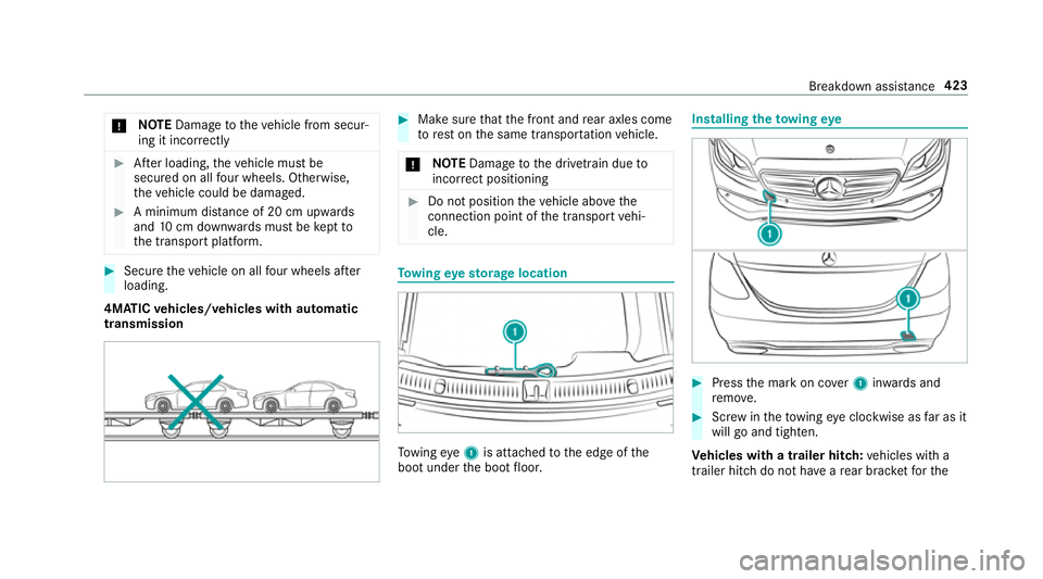
wing eyesto rage location To
wing eye1 is attached tothe edge of the
boot under the boot floor. Installing
theto wing eye #
Press the mark on co ver1 inwa rds and
re mo ve. #
Screw intheto wing eyeclockwise as far as it
will go and tighten.
Ve hicles with a trailer hitch: vehicles with a
trailer hitch do not ha veare ar brac ketfo rthe Breakdown assis
tance 423
Page 428 of 589
#
When the fuse box is open, make sure
th at no moisture can enter the fuse
box. #
When closing the fuse box, make sure
th at the seal of the lid is positioned cor‐
re ctly on the fuse box. If
th e newly inser ted fuse also blo ws, ha vethe
cause traced and rectified at a qualified special‐
ist workshop, e.g. a Mercedes-Benz Service
Centre.
Ensure thefo llowing before replacing a fuse:
R The vehicle is secured against rolling away.
R All electrical consumers are switched off.
R The ignition is switched off.
The electrical fuses are located in various fuse
bo xes:
R Fuse box in the engine compartment on the
driver's side (→ page 425)
R Fuse box on the driver's side of the dash‐
board (→ page 426) R
Fuse box in the front passenger foot we ll
(→ page 426)
R Fuse box in the boot on theright-hand side
of theve hicle, when vie wed in the direction
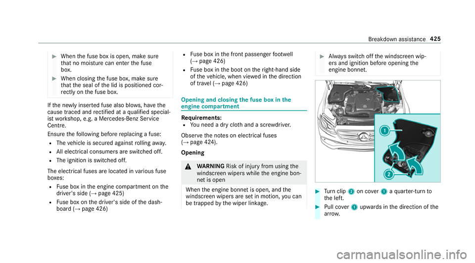
of tr avel (→ page 426) Opening and closing
the fuse box in the
engine compa rtment Re
quirements:
R You need a dry clo thand a sc rewdriver.
Obser vethe no tes on electrical fuses
(→ page 424).
Opening &
WARNING Risk of inju ryfrom using the
windscreen wipers while the engine bon‐
net is open
When the engine bonn etis open, and the
windscreen wipers are set in motion, you can
be trapped bythe wiper linkage. #
Alw ays switch off the windscreen wip‐
ers and ignition before opening the
engine bonn et. #
Turn clip 2on co ver1 aqu arter-turn to
th e left. #
Pull co ver1 upwards in the direction of the
ar row. Breakdown assis
tance 425
Page 436 of 589
Ra
dio equipment appr oval of the ty repres‐
sure moni toring sy stem
Ra dio equipment appr oval numbers Countr
yRadio equipment appr oval
number
Ar ge ntina Schrader AG5SP4
Numero de Registro CNC:
H-1 4795
Brazil MODELO:
AG5SP4-D
AN ATEL: 0280-15-8001
Es te equipamento opera em
caráter secundário, is toé, não
te m direito à pr oteção contrain‐
te rferência prejudicial, mesmo de
es tações do mesmo tipo e não
pode causar inter ferê ncia a si ste‐
mas operando em caráter pri‐
mário. Countr
yRadio equipment appr oval
number
European
Union Hereb
y,Schrader Electronics Ltd
declares that thera dio equip‐
ment type "AG5SP4 & MFR" is in
compliance with Directive
20 14 /53/EU.
The full text of the EU declaration
of confo rmity is available at the
fo llowing internet address:
http://www.tpmseuro‐
shop.com/documents/declara‐
tion_conformities
GG4: f = 433.92MHz; Maximum
ef fective radiated P < 10mw
(e.r.p)
MFR recei ver:Category II
Schrader Elect ronics Ltd. 11
Te ch nology Park, Count
ryRadio equipment appr oval
number
Belfast Road, Antrim BT41 1QS,
Nor thern Ireland United Kingdom
Indonesia 38892/SDPPI/20 15
Jordan Kingdom of Jordan Type appr oval
fo rTy re Pressure sensor.
Manufacturer: Schrader Elect ron‐
ics Ltd.
Model: AG5SP4
Ty pe Appr oval Numb er:
TRC/LPD/20 15/21
MFR
Ty pe Appr oval Numb er:
TRC/LPD/20 15/223 Wheels and tyres
433
Page 450 of 589
Re
moving the eme rgency spa rewheel The eme
rgency spare wheel is secured in the
emer gency spa rewheel bag in the boot. #
Obser vethe information on mounting tyres
(→ page 436). #
Open the boot. #
Detach thefast ening stra ps. #
Unhook there taining spring hooks of thefa s‐
te ning stra ps from the brac kets. #
Remo vethe emer gency spa rewheel bag with
th e emer gency spa rewheel. #
Open the emer gency spa rewheel bag and
re mo vethe emer gency spa rewheel. Wheels and tyres
447
Page 482 of 589
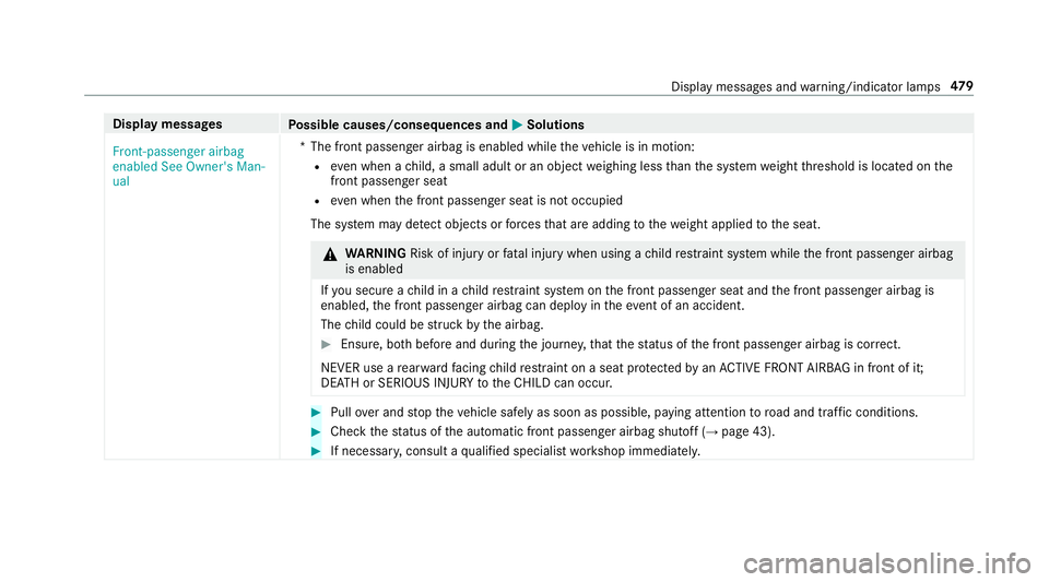
Display messages
Possible causes/consequences and M
MSolutions
Front-passenger airbag
enabled See Owner's Man-
ual *T
he front passenger airbag is enabled while theve hicle is in motion:
R even when a child, a small adult or an object weighing less than the sy stem weight thre shold is located on the
front passenger seat
R even when the front passenger seat is not occupied
The sy stem may de tect objects or forc es that are adding tothewe ight applied tothe seat. &
WARNING Risk of inju ryor fata l injury when using a child restra int sy stem while the front passenger airbag
is enabled
If yo u secure a child in a child restra int sy stem on the front passenger seat and the front passenger airbag is
enabled, the front passenger airbag can deploy in theev ent of an accident.
The child could be stru ck bythe airbag. #
Ensure, bo thbefore and during the journe y,that thest atus of the front passenger airbag is cor rect.
NEVER use a rear wa rdfacing child restra int on a seat pr otected byan ACTIVE FRONT AIRB AGin front of it;
DE ATH or SERIOUS INJU RYtotheCH ILD can occur. #
Pull over and stop theve hicle safely as soon as possible, paying attention toroad and traf fic conditions. #
Check thest atus of the automatic front passenger airbag shutoff (→ page 43). #
If necessar y,consult a qualified specialist workshop immediatel y. Displ
aymessa ges and warning/indicator lamps 47 9
Page 514 of 589
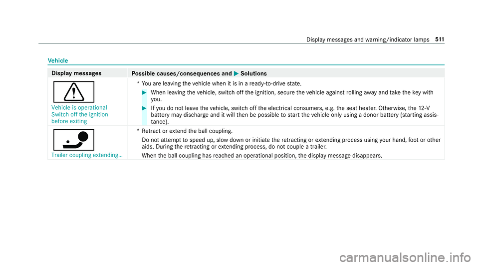
Ve
hicle Display messages
Possible causes/consequences and M
MSolutions
d Vehicle is operational
Switch off the ignition
before exiting *Y
ou are leaving theve hicle when it is in a ready-to-drive state. #
When leaving theve hicle, switch off the ignition, secure theve hicle against rolling away and take theke y with
yo u. #
Ifyo u do not lea vetheve hicle, switch off the electrical consumers, e.g. the seat heater. Otherwise, the12 ‑V
battery may discharge and it will then be possible tostart theve hicle only using a donor battery (s tarting assis‐
ta nce).
ï Trailer coupling extending… *R
etra ct or extend the ball coupling.
Do not attem pttospeed up, slow down or initiate there tracting or extending process using your hand, foot or other
aids. During there tracting or extending process, do not couple a traile r.
When the ball coupling has reached an operational position, the display message disappears. Display messages and
warning/indicator lamps 511
Page 515 of 589
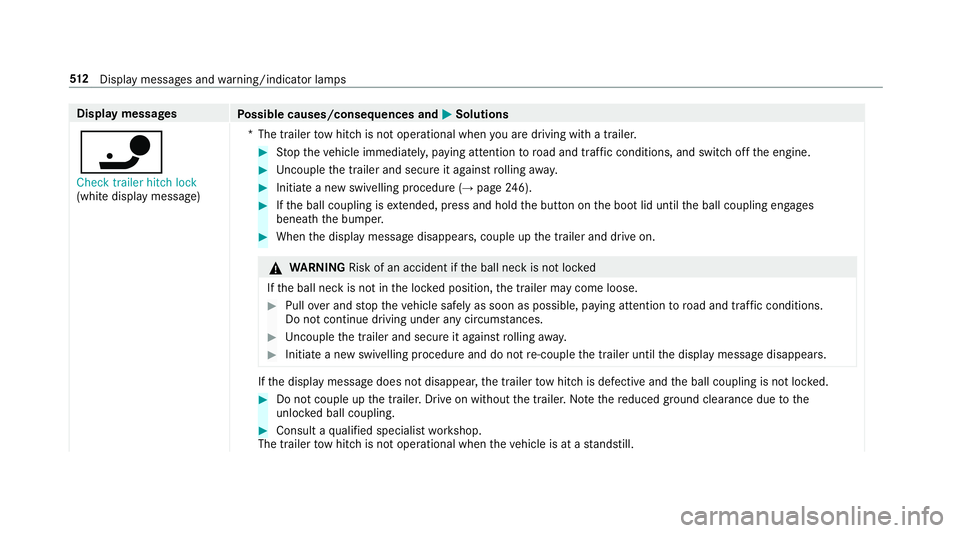
Display messages
Possible causes/consequences and M
MSolutions
ï Check trailer hitch lock
(white display message) *T
he trailer tow hit chis not operational when you are driving with a trailer. #
Stop theve hicle immediately, paying attention toroad and traf fic conditions, and switch off the engine. #
Uncouple the trailer and secure it against rolling away. #
Initiate a new swivelling procedure (→ page246). #
Ifth e ball coupling is extended, press and hold the button on the boot lid until the ball coupling engages
beneath the bumper. #
When the display message disappears, couple up the trailer and drive on. &
WARNING Risk of an accident if the ball neck is not loc ked
If th e ball neck is not in the loc ked position, the trailer may come loose. #
Pull over and stop theve hicle safely as soon as possible, paying attention toroad and traf fic conditions.
Do not continue driving under any circums tances. #
Uncouple the trailer and secure it against rolling away. #
Initiate a new swivelling procedure and do not re-couple the trailer until the display message disappears. If
th e display message does not disappear, the trailer tow hit chis defective and the ball coupling is not loc ked. #
Do not couple up the trailer. Drive on without the trailer. No tethere duced ground clearance due tothe
unlo cked ball coupling. #
Consult a qualified specialist workshop.
The trailer tow hit chis not operational when theve hicle is at a standstill. 512
Displaymessa ges and warning/indicator lamps
Page 516 of 589
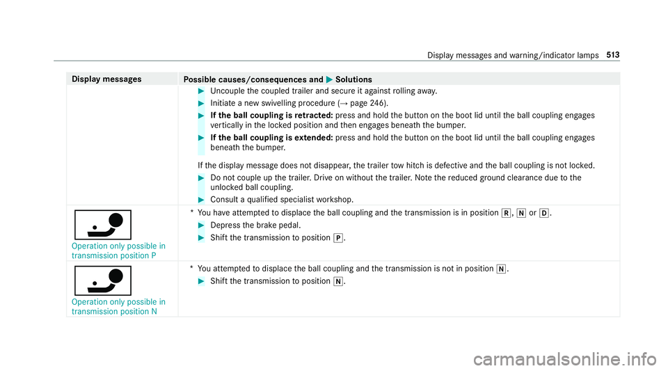
Display messages
Possible causes/consequences and M
MSolutions #
Uncouple the coupled trailer and secure it against rolling away. #
Initiate a new swivelling procedure (→ page246). #
Ifth e ball coupling is retracted: press and hold the button on the boot lid until the ball coupling engages
ve rtically in the loc ked position and then engages beneath the bumper. #
Ifth e ball coupling is extended: press and hold the button on the boot lid until the ball coupling engages
beneath the bumper.
If th e display message does not disappear, the trailer tow hit chis defective and the ball coupling is not loc ked. #
Do not couple up the trailer. Drive on without the trailer. No tethere duced ground clearance due tothe
unlo cked ball coupling. #
Consult a qualified specialist workshop.
ï Operation only possible in
transmission position P *
Yo u ha veattem ptedto displace the ball coupling and the transmission is in position k,iorh. #
Depress the brake pedal. #
Shift the transmission toposition j.
ï Operation only possible in
transmission position N *
Yo u attem ptedto displace the ball coupling and the transmission is not in position i. #
Shift the transmission toposition i. Display messages and
warning/indicator lamps 513
Page 537 of 589
Ve
hicle Wa
rning/indicator lamp
Possible causes/consequences and M
MSolutions
ï Tr ailer tow hit chwarning
lamp The
red trailer tow hit chwarning lamp is on.
The trailer tow hit chis not operational or swivels. &
WARNING Risk of an accident if the ball neck is not loc ked
If th e ball neck is not in the loc ked position, the trailer may come loose. #
Pull over and stop theve hicle safely as soon as possible, paying attention toroad and traf fic conditions. Do
not continue driving under any circums tances. #
Uncouple the trailer and secure it against rolling away. #
Initiate a new swivelling procedure and do not re-couple the trailer until the display message disappears. #
Obser vethe messages on the multifunction displa y.
If th e trailer hitch swivels: #
Wait until the ball coupling has reached the operational position. 534
Display messages and warning/indicator lamps
Page 551 of 589
Re
ar side wind ows................................. 65
Child seat Attach ing (no tes) ................................... 56
Fr ont passenger seat (no tes) ................. 54
Fr ont passenger seat (rear ward-
fa cing/for ward-facing) .......................... 55
Fr ont passenger seat (without auto‐
matic airbag shutoff) ............................. 55
ISOFIX/i-Size (fitting) ............................. 51
No tes on the safe transpor tation of
ch ildren ................................................ .47
Re commended child restra int sys‐
te ms ...................................................... 62
Seats suita blefor belt-secu redch ild
re stra int sy stems ................................... 57
Seats suitable for i‑Size child
re stra int sy stems ................................... 61
Seats suitable for ISOFIX child
re stra int sy stems ................................... 59
To pTe ther ..............................................53
Child seat see i-Size child seat securing sy stem
see ISOFIX child seat securing sy stem
Children Notes on safe transpor tation ................. 47Chock
...................................................... .440
St orage location ..................................4 40
Cho ck
see Chock
CI+ module ..............................................3 83
Calling up a menu ................................ 383
CI+ module (TV) Inserting a Smart Card ........................ 383
Cigar ette lighter
Fr ont centre console ............................ 11 7
City lighting .............................................. 127
Cleaning see Care
Climate control ........................................ 137
Ac tivating/deactivating the A/C
function (cont rol panel) ...................... .138
Ac tivating/deactivating the A/C
function (multimedia sy stem) .............. 13 8
Ac tivating/deactivating the synchro‐
nisation function (cont rol panel) .......... 13 9
Ac tivating/deactivating the synchro‐
nisation function (multimedia sys‐
te m) ..................................................... 14 0Air di
stribution settings .......................1 39
Air-recirculation mode ......................... 14 0
Au tomatic control ................................ 13 9
Climate style function .......................... 13 9
Defrosting the windscreen ...................1 37
Demi sting windo ws............................. 14 0
Fr ont air vents ..................................... 147
Glo vebox air vent ................................ 14 8
Inserting/removing theflacon (fra‐
gr ance sy stem) .................................... 141
Ionisation ............................................. 14 0
Re ar air vents ....................................... 147
Re ar operating unit .............................. 137
Re sidual heat ....................................... 14 0
Sets the air flow ................................... 137
Setting rear climate control (multi‐
media sy stem) .....................................1 39
Setting the air distribution ...................1 37
Setting the climate style ......................1 39
Setting the fragrance sy stem ............... 14 0
Setting thete mp erature ......................1 37
St ationary heater/ ventilation .............. 14 2
Switching on/off ................................. 13 8
Switching there ar wind owheater
on/off .................................................. 137
THERMATIC contro l panel .................... 137548
Index