display MERCEDES-BENZ CLS COUPE 2020 User Guide
[x] Cancel search | Manufacturer: MERCEDES-BENZ, Model Year: 2020, Model line: CLS COUPE, Model: MERCEDES-BENZ CLS COUPE 2020Pages: 469, PDF Size: 8.47 MB
Page 54 of 469
th
e dis tance between the door and theve hicle
occupant.
If PRE-SAFE ®
Impulse Side has been deplo yed or
is faulty, thePRE-SAFE impulse side inoperative
See Owner's Manual display message appears
(/ page 361). Safely transporting
children in theve hicle Alw
ays obser vewhen children are tr avelling
in theve hicle %
Also strictly obser vethe saf ety no tesfo rthe
specific situation. In this wa yyo u can recog‐
nise po tential risks and avoid dangers if chil‐
dren are tr avelling in theve hicle
(/ page 52).
Be diligent
Bear in mind that negligence when securing a
ch ild in thech ild restra int sy stem may ha veseri‐
ous consequences. Alw ays be diligent in secur‐
ing a child carefully before everyjou rney. To
impr oveprotection forch ildren younger than
12 years old or under 1.50 m in height,
Mercedes-Benz recommends you obse rvethe
fo llowing information:
R Alw ays secure thech ild in a child restra int
sy stem suitable forth is Mercedes-Benz vehi‐
cle.
R The child restra int sy stem must be appropri‐
ate tothe age, weight and size of thech ild.
R The vehicle seat must be suitable forfitting a
ch ild restra int sy stem (/ page 55).
Ac cident statistics show that children secured
on there ar seats are general lysafer than chil‐
dren secured on the front seats. Forth is reason,
Mercedes-Benz strongly advises that youfit a
ch ild restra int sy stem toare ar seat.
The generic termchild restra int sy stem
The generic term child restra int sy stem is used
in this Owner's Manual. A child restra int sy stem
is, forex ample:
R a baby car seat
R are ar wa rd-f acing child seat R
afo rw ard-facing child seat
R ach ild boos ter seat with a backrest and seat
belt guide
Mercedes-Benz recommends using a child
boos ter seat with a backrest.
The child restra int sy stem must be appropriate
to the age, weight and size of thech ild.
Obser velaws and legal requ irements
Alw ays obser vethe legal requ irements when
using a child restra int sy stem in theve hicle.
Make sure that thech ild restra int sy stem is
appr oved in accordance with theva lid test speci‐
fi cations and guidelines. Further information can
be obtained at a qualified specialist workshop.
Mercedes-Benz recommends that you use a
Mercedes-Benz Service Centre forth is purpose.
Only use appr ovedch ild restra int sy stems
On lych ild restra int sy stems that meet thefo l‐
lowing UNECE standards are permit tedfo r use in
th eve hicle:
R UN-R44
R UN-R129 (i-Size child restra int sy stems) Occupant saf
ety51
Page 63 of 469
on
the multifunction display on the instrument
clus ter.
If th e cent reseat backrest is not engaged and
loc ked in place, there d lock verification indica‐
to r will be visible. &
WARNING Risk of inju ryor death if the
permissible gross mass of thech ild and
ch ild restra int sy stem toget her is excee‐
ded.
To o much load may be placed on the ISOFIX
or i‑Size child restra int sy stems and thech ild
may not be restra ined cor rectly in theeve nt
of an accident, forex ample. #
Ifth ech ild and thech ild restra int sys‐
te m toget her weigh more than 33 kg,
only use an ISOFIX or i‑Size child
re stra int sy stem with which thech ild is
secured with theve hicle seat belt. #
Also secure thech ild restra int sy stem
with theTo pTe ther belt, if available. Alw
ays comply with the information about the
mass of thech ild restra int sy stem:
R inthe manufacturer's ins tallation and operat‐
ing instructions forth ech ild restra int sy stem
used
R on a label on thech ild restra int sy stem, if
present
Re gular lych eck that the permissible gross mass
of thech ild and child restra int sy stem is still
complied with.
When fitting a child restra int sy stem, obser ve
th efo llowing:
O Alw
ays obser vethe cor rect use of the seats
and consider their suitability for attaching a
ch ild restra int sy stem.
ISOFIX child seat securing sy stem
(/ page 58)
or
i‑Size child seat securing sy stem
(/ page 59) O
Alw
ays comply with the manufacturer's
ins tallation and operating instructions for
th ech ild restra int sy stem used.
O Make sure
that thech ild's feet do not touch
th e front seat. If necessar y,mo vethe front
seat slightly forw ards.
®When fitting an ISOFIX child restra int sys‐
te m, also obser vethefo llowing:
O When using a baby car seat in
weight
gr oup 0/0+ and a rear wa rd-facing child
re stra int sy stem in weight group I on a
re ar seat: adjustthe front seat so that the
seat does not touch thech ild restra int sys‐
te m.
O When using a
forw ard-facing child
re stra int sy stem of weight group I: the
backrest of thech ild restra int sy stem must
lie as flat as possible against the backrest of
th eve hicle seat.
O If
th e head restra int of thech ild seat cannot
be fully extended when it is ins talled in the
ve hicle, this will result in restrictions on the
maximum size setting forch ild restra int sys‐
te ms in weight group 2 or 3. 60
Occupant sa fety
Page 65 of 469
#
Alw ays lock rear seat backrests af ter
fi tting TopTe ther belts. #
Obser vethe lock verification indicator. If
th e left and right seat backrests are not
engaged and loc ked in place, this will be shown
on the multifunction display on the instrument
clus ter.
If th e cent reseat backrest is not engaged and
loc ked in place, there d lock verification indica‐
to r will be visible.
¯ Ifth ech ild restra int sy stem is equipped
with a TopTe ther belt:
The risk of injury may be reduced byTo p
Te ther. The TopTe ther belt enables an
additional connection between thech ild
re stra int sy stem attached with ISOFIX or
i‑Size and theve hicle. #
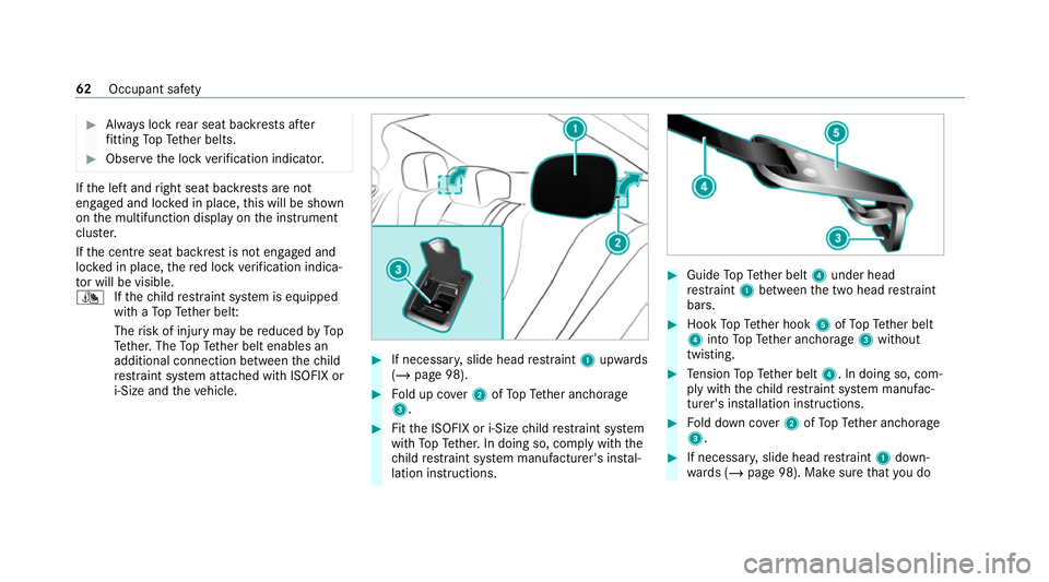
If necessar y,slide head restra int 1 upwards
(/ page 98). #
Fold up co ver2 ofTopTe ther anchorage
3. #
Fitthe ISOFIX or i‑Size child restra int sy stem
with TopTe ther. In doing so, comply with the
ch ild restra int sy stem manufacturer's ins tal‐
lation instructions. #
Guide TopTe ther belt 4under head
re stra int 1 between the two head restra int
bars. #
Hook TopTe ther hook 5ofTopTe ther belt
4 into TopTe ther anchorage 3without
twisting. #
Tension TopTe ther belt 4. In doing so, com‐
ply with thech ild restra int sy stem manufac‐
turer's ins tallation instructions. #
Fold down co ver2 ofTopTe ther anchorage
3. #
If necessar y,slide head restra int 1 down‐
wa rds (/ page 98). Make sure that you do 62
Occupant saf ety
Page 68 of 469
on
the multifunction display on the instrument
clus ter.
If th e cent reseat backrest is not engaged and
loc ked in place, there d lock verification indica‐
to r will be visible.
When fitting a belt-secured child restra int
sy stem, obser vethefo llowing:
O Alw
ays comply with the manufacturer's
ins tallation and operating instructions for
th ech ild restra int sy stem used.
O Fo
r a child restra int sy stem in the "Univer‐
sal" or "Semi-Universal" categor y,make
sure that the sy stem has been appr oved for
th eve hicle seat.
Obser vethe no tes under "Suitability of
seats for attaching belt-secu redch ild
re stra int sy stems" (/ page 63).
O When using a
weight category 0/0+
baby car seat and a weight category I
re ar wa rd-facing child restra int sy stem
on a rear seat: adjustthe front seat so that
th e seat does not touch thech ild restra int
sy stem. O
The backrest of
thefo rw ard-facing child
re stra int sy stem must, as far as possible, be
re sting on the seat backrest of there ar
seat.
O If
th e head restra int of thech ild seat cannot
be fully extended when it is ins talled in the
ve hicle, this will result in restrictions on the
maximum size setting forch ild restra int sys‐
te ms in weight category II or III.
Contact with thero of when the head
re stra int is fully extended and lo cked in
place will not result in any restrictions on
use.
O The
child restra int sy stem must not be put
under stra in between thero of and the seat
cushion and/or be fitted facing the wrong
direction. Where possible, adjust the seat
cushion inclination accordingly.
O The
child restra int sy stem must not be put
under stra in by the head restra int. Adjust
th e head restra ints as appropriate.
O Make sure
that thech ild's feet do not touch
th e front seat. If necessar y,mo vethe front
seat slightly forw ards. #
Install thech ild restra int sy stem.
The entire base of thech ild restra int sy stem
must alw aysre st on the sitting sur face of the
re ar seat. #
Alw ays make sure that the shoulder belt
st ra p is cor rectly routed from the seat belt
outlet of theve hicle tothe shoulder belt
guide on thech ild restra int sy stem.
The shoulder belt stra p must be routed for‐
wa rds and down wards from the seat belt out‐
let. Occupant saf
ety65
Page 109 of 469
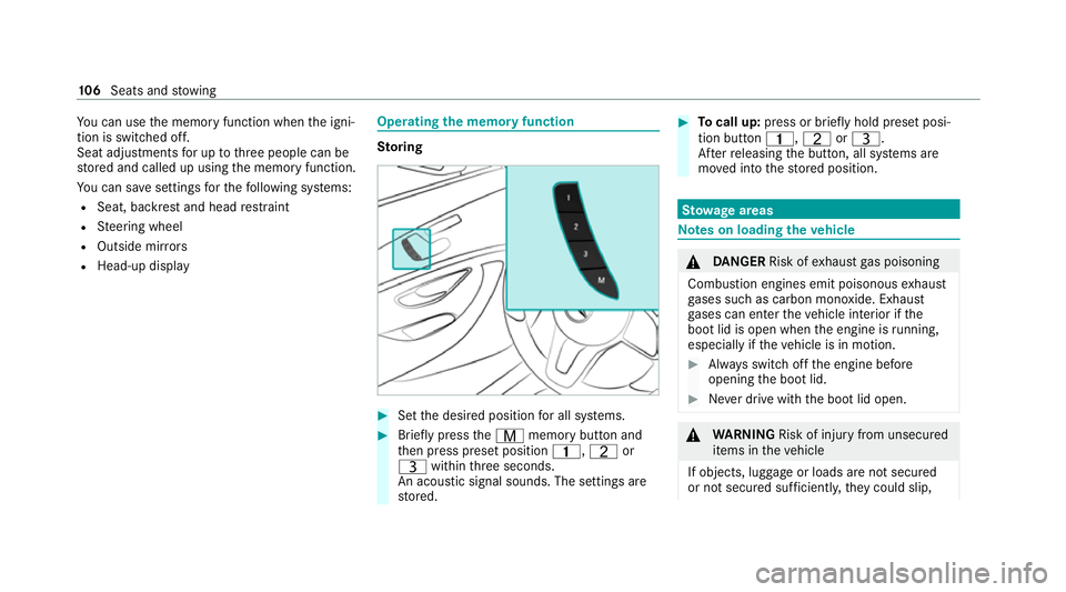
Yo
u can use the memory function when the igni‐
tion is switched off.
Seat adjustments for up tothre e people can be
st ored and called up using the memory function.
Yo u can sa vesettings forth efo llowing sy stems:
R Seat, backrest and head restra int
R Steering wheel
R Outside mir rors
R Head-up display Operating
the memory function St
oring #
Set the desired position for all sy stems. #
Brief lypress theV memory button and
th en press preset position 4,Tor
U within thre e seconds.
An acoustic signal sounds. The settings are
st ored. #
Tocall up: press or brief lyhold preset posi‐
tion button 4,TorU.
Af terre leasing the button, all sy stems are
mo ved into thestored position. St
ow age areas Note
s on loading theve hicle &
DANG ER Risk of exhaust gas poisoning
Combustion engines emit poisonous exhaust
ga ses such as carbon monoxide. Exhaust
ga ses can enter theve hicle interior if the
boot lid is open when the engine is running,
especially if theve hicle is in motion. #
Alw ays switch off the engine before
opening the boot lid. #
Never drive with the boot lid open. &
WARNING Risk of inju ryfrom unsecu red
items in theve hicle
If objects, luggage or loads are not secured
or not secured suf ficientl y,they could slip, 106
Seats and stowing
Page 112 of 469
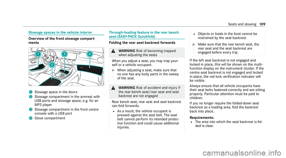
St
ow age spaces in theve hicle interior Overview of
the front stowage compa rt‐
ments 1
Stow age space in the doors
2 Stow age compartment in the armrest with
USB ports and stowage space, e.g. for an
MP3 pla yer
3 Stow age compartment in the front cent re
console wi tha USB port
4 Glovecompa rtment Through-loading
feature in there ar ben ch
seat (EAS Y-PA CK Quickfold) Fo
lding there ar seat backrest forw ards &
WARNING Risk of becoming trapped
when adjusting the seats
When you adjust a seat, you may trap your‐
self or a vehicle occupant. #
When adjusting a seat, make sure that
no one has any body parts in the sweep
of the seat. &
WARNING Risk of accident and inju ryif
th ere ar ben chseat/rear seat and seat
backrest are not engaged
Re ar ben chseat, rear seat and seat backrest
can fold forw ards.
R As a result, theve hicle occupant is
pressed against the seat belt. The seat
belt cann otper form its intended pr otec‐
tive function and could cause additional
injuries. R
Objects or loads in the boot cann otbe
re stra ined bythe seat backrest. #
Make sure that there ar ben chseat, the
re ar seat and the seat backrest are
engaged before everytrip. If
th e left seat backrest is not engaged and
loc ked in place, this will be shown on the multi‐
function display on the instrument clus ter.If the
centre seat ba ckrest is not engaged and loc ked
in place, there d lock verification indicator will
be visible.
Alw ays ensure that all vehicle occupants ha ve
th eir seat belts fastened cor rectly and are sitting
prope rly. Pa rticular attention must be paid to
ch ildren.
If yo u no lon gerre qu ire thefo lded-d own seat
ba ckrest as a loading area, fold the backrest
back into place.
Re quirements:
R The area into which the seat backrest is fol‐
ded is clear. Seats and
stowing 109
Page 121 of 469
not be able
tobe charge d or connec ted with
th eve hicle's exterior aerial.
R The mobile phone may heat up during the
ch arging process. This may particular ly
depend on the applications (apps) cur rently
open in the bac kground.
R Toensure more ef ficient charging and con‐
nection with theve hicle's exterior aerial,
re mo vethe pr otective co ver from the mobile
phone. Pr otective co vers which are neces‐
sary for wireless charging are excluded.
R When charging, the mat should be used if
possible. Wire
lessly charging a mobile phone Requ
irements:
R The mobile phone is suitable for wireless
ch arging (Qi-compatible mobile phone).
A list of Qi-compatible mobile phones can be
fo und at: https://www.mercedes-benz-
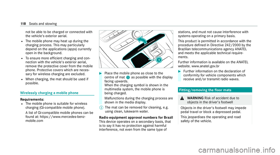
mobile.com #
Place the mobile phone as close tothe
centre of mat 1as possible wi th the display
fa cing up wards.
When thech arging symbol is shown in the
multimedia sy stem, the mobile phone is
being charge d.
Malfunctions during thech arging process are
shown in the media displa y.
% The mat can be remo vedfo r cleaning, e.g.
using clean, luk ewarmwate r.
Ra dio equipment appr oval numbers for Brazil
This device operates on a secondary basis, that
is to say it has no pr otection against harmful
inter fere nce, not even from the same type of st
ations, and must not cause inter fere nce wi th
sy stems operating on a primary basis.
This product is permitted in accordance with the
procedure defined in Directive 242/2000 bythe
Brazilian telecommunications agency AN ATEL
and meets the applicable tech nical requ ire‐
ments.
Fu rther information is available on the AN ATEL
we bsite. www.anatel.go v.br #
Further information on the declaration of
confo rmity forve hicle components which
re cei veand/or transmit radio wav es. Fi
tting/ removing the floormats &
WARNING Risk of accident due to
objects in the driver's foot we ll
Objects in the driver's foot we ll may impede
pedal tr avel or block a depressed pedal.
This jeopardises the operating and road
saf ety of theve hicle. 11 8
Seats and stowing
Page 131 of 469
R
If highly reflective signs are de tected, ULTRA
RANGE Highbeam will be switched off au to‐
matical ly.
At speeds greater than appr oximately 50 km/h:
R The headlamp range of the low beam is regu‐
lated automatically based on the dis tance to
ot her road users.
The sy stem's optical sensor is located behind
th e windscreen near theove rhead control panel.
Switching Adaptive Highbeam Assist Plus
on/off
Switching on #
Turn the light switch tothe à position. #
Switch on the high beam using the combina‐
tion switch.
When the high beam is switched on automat‐
ically in the dar k,the_ indicator lamp on
th e multifunction display will light up.
Switching off #
Switch off the high beam using the combina‐
tion switch. Setting
the low beam (vehicles with MULTI‐
BEAM LED headlamps only) Multimedia sy
stem:
4 © 5
Settings 5
Lights
5 Dipped-beams #
Select Right-side traffic, Left-side trafficor
Automatic. Setting
theex terior lighting switch-off delay
time Re
quirements:
R The light switch is in theà position.
Multimedia sy stem:
4 © 5
Settings 5
Lights
5 Ext. light. del. sw. off #
Set the switch-off delay time.
When theve hicle engine is switched off, the
ex terior lighting will be activated forth e set
time. Switching
the sur round lighting on/off Multimedia sy
stem:
4 © 5
Settings 5
Lights
5 Surround lighting
When Surround lighting is active,theex terior
lighting lights up for 40 seconds af terth eve hicle
is unloc ked. When youstart theve hicle, the sur‐
ro und lighting is deactivated and the automatic
driving lights are activated. #
Activate or deacti vate the function. 12 8
Light and sight
Page 135 of 469
#
Foldthe wiper arms back onto the wind‐
screen. #
Switch on the ignition. #
Press theî button on the combination
switch (/ page130).
The wiper arms will return tothe original
position. #
Switch the ignition off. Maintenance display #
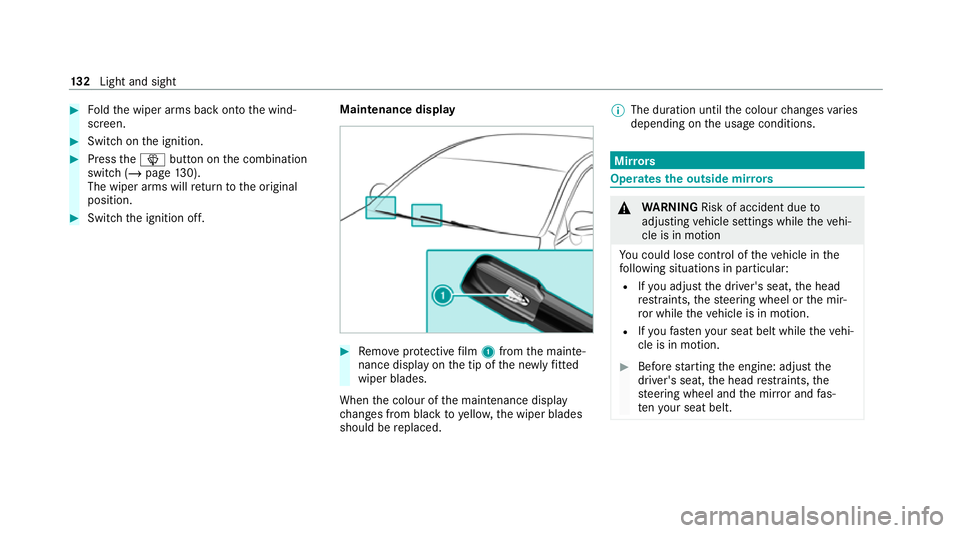
Remo veprotective film 1 from the mainte‐
nance display on the tip of the newly fitted
wiper blades.
When the colour of the maintenance display
ch anges from black to yellow, the wiper blades
should be replaced. %
The duration until the colour changes varies
depending on the usage conditions. Mir
rors Operates
the outside mir rors &
WARNING Risk of accident due to
adjusting vehicle settings while theve hi‐
cle is in motion
Yo u could lose cont rol of theve hicle in the
fo llowing situations in particular:
R Ifyo u adjust the driver's seat, the head
re stra ints, thesteering wheel or the mir‐
ro r while theve hicle is in motion.
R Ifyo ufast enyour seat belt while theve hi‐
cle is in motion. #
Before starting the engine: adjust the
driver's seat, the head restra ints, the
st eering wheel and the mir ror and fas‐
te nyo ur seat belt. 13 2
Light and sight
Page 141 of 469
A
Vehicles with THERMATIC air conditioning
contro l panel: ¿switches the A/C func‐
tion on/off (/ page138)
Ve hicles with THERMOTRONIC air condition‐
ing contro l panel:_adjusts the air distri‐
bution, right
B w Setsthete mp erature, right
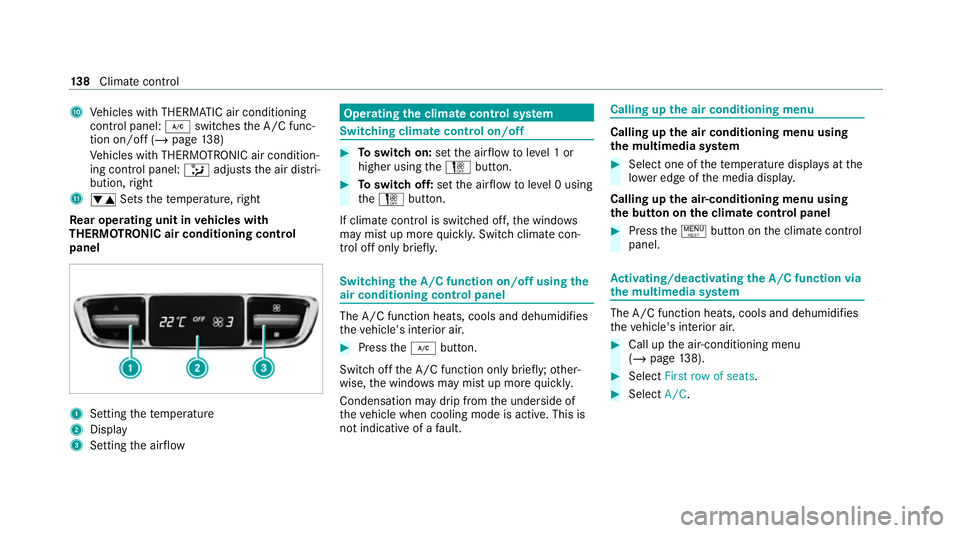
Re ar operating unit in vehicles with
THERMOTRONIC air conditioning control
panel 1
Setting thete mp erature
2 Display
3 Setting the air flow Operating
the clima tecont rol sy stem Switching clima
tecont rol on/off #
Toswitch on: setthe air flow toleve l 1 or
higher using theH button. #
Toswitch off: setthe air flow toleve l 0 using
th eH button.
If climate control is switched off, the windo ws
may mist up more quickl y.Switch climate con‐
trol off only brie fly. Switching
the A/C function on/off using the
air conditioning control panel The A/C function heats, cools and dehumidi
fies
th eve hicle's interior air. #
Press the¿ button.
Switch off the A/C function only brief ly;ot her‐
wise, the windo wsmay mist up more quickl y.
Condensation may drip from the underside of
th eve hicle when cooling mode is active. This is
not indicative of a fault. Calling up
the air conditioning menu Calling up
the air conditioning menu using
th e multimedia sy stem #
Select one of thete mp erature displa ysatthe
lo we r edge of the media displa y.
Calling up the air-conditioning menu using
th e but ton on the clima tecont rol panel #
Press the! button on the climate control
panel. Ac
tivating/deactivating the A/C function via
the multimedia sy stem The A/C function heats, cools and dehumidifies
th eve hicle's interior air. #
Call up the air-conditioning menu
(/ page 138). #
Select First row of seats. #
Select A/C. 13 8
Climate cont rol