air suspension MERCEDES-BENZ CLS COUPE 2020 Owners Manual
[x] Cancel search | Manufacturer: MERCEDES-BENZ, Model Year: 2020, Model line: CLS COUPE, Model: MERCEDES-BENZ CLS COUPE 2020Pages: 469, PDF Size: 8.47 MB
Page 26 of 469
#
Ifth ere is damage, consult a qualified
specialist workshop immediately. *
NO
TEDama getotheve hicle due todriv‐
ing toofast and due toimpacts tothe
ve hicle underbody or suspension compo‐
nents In
thefo llowing situations, in particular, there
is a risk of damage totheve hicle:
R theve hicle becomes grounded, e.g. on a
high kerb or an unpa vedro ad
R theve hicle is driven toofast over an
obs tacle, e.g. a kerb, speed bump or pot‐
hole
R a heavy object strike sth e underbody or
suspension components
In situations such as these, damage tothe
body, underbody, suspension components,
wheels or tyres may not be visible. Compo‐
nents damaged in this wa y can unexpec tedly
fa il or, in the case of an accident, may no lon‐
ge r absorb there sulting forc e as intended. If
th e underbody panelling is damaged, flam‐
mable materials such as lea ves, grass or
twigs can collect between the underbody and
th e underbody panelling. These materials
may ignite if they come into contact wi thhot
parts of theex haust sy stem. #
Have theve hicle checked and repaired
immediately at a qualified specialist
wo rkshop.
or #
If driving saf ety is impaired while con‐
tinuing your journe y,pull over and stop
th eve hicle immediatel y,while paying
attention toroad and traf fic conditions,
and contact a qualified specialist work‐
shop. Ve
hicles with a 48 V on-board electrical sys‐
te m (EQ Boo sttech nology) &
DANG ER Risk of fata l injury bytouching
damaged high-voltage co mponents
Ve hicles with a 48 V on-board electrical sys‐
te m contain individual high-voltage compo‐
nents. These high-voltage components are
under high voltage.
If yo u modify co mponent parts of these high-
vo ltage components or touch damaged com‐
ponent parts, you may be electrocuted.
High voltage components may be damaged
in an accident, although the damage may not
be visible. #
Never per form modifications tocompo‐
nent pa rts of high-voltage components. #
Neverto uch damaged co mponent parts
of high-voltage components. #
Neverto uch co mponent parts of high-
vo ltage components af ter an accident. General no
tes23
Page 36 of 469
In cer
tain cases, it may be requ ired tostore data
th at wo uld ha veotherwise been used only tem‐
porarily. This may be the case if theve hicle has
de tected a malfunction, forex ample.
If yo u use services, such as repair services and
maintenance work,st ored operational data as
we ll as theve hicle identification number can be
re ad out and used. They can be read out by
service network emplo yees, such as workshops
and manufacturers or third parties, such as
breakdown services. The same is true in the
case of warranty claims and quality assurance
measures.
In general, there ad out is per form ed via the
legally prescribed port forth e diagnostics con‐
nection in theve hicle. The operational data that
are read out document tech nical states of the
ve hicle or of individual components and assist in
th e diagnosis of malfunctions, compliance with
wa rranty obligations and quality impr ovement.
To that end, these data, in particular information
about component loads, tech nical events, mal‐
functions and other faults may be transmit ted
along with theve hicle identification number to
th e manufacturer. Furthermore, the manufac‐ turer is subject
toproduct liability. Forth is rea‐
son the manufacturer also uses operational data
from theve hicle, forex ample, forre calls. These
da ta can also be used toexamine the cus tom‐
er's warranty and guarantee claims.
Fa ult memories in theve hicle can be reset by a
service outlet or at your requ est as part of repair
or maintenance work.
Con venience and inf otainment functions
Yo u can store con venience settings and individ‐
ual settings in theve hicle and change or reset
th em at any time.
Depending on theve hicle equipment, this
includes thefo llowing settings, forex ample:
R seat and steering wheel positions
R suspension and climate control settings
R individual settings, such as interior lighting
Depending on the selected equipment, you can
import data into vehicle inf otainment functions
yo urself. Depending on
theve hicle equipment, this
includes thefo llowing data, forex ample:
R multimedia data, such as music, films or pho‐
to sfo r playback in an integrated multimedia
sy stem
R address book data for use in connection with
an integrated hands-free sy stem or an inte‐
grated navigation sy stem
R entered navigation destinations
R data about the use of Internet services
These data for con venience and inf otainment
functions may be sa ved locally in theve hicle or
th ey may be located on a device which you ha ve
connected totheve hicle, such as a smartphone,
USB flash drive or MP3 pla yer.If yo u ha ve
entered these data yourself, you can dele tethem
at any time.
This data is transmit ted from theve hicle tothird
parties only at your requ est. This applies, in par‐
ticular, when you use online services in accord‐
ance with the settings that you ha veselected. General no
tes33
Page 163 of 469
R
only suitable for good road conditions, a dry
ro ad sur face and a clear stre tch of road
C Sport
R continues toofferst ability but with a sporty
setup
R allowsthe sporty driver a more active driving
st yle
R only suitable for good road conditions, a dry
ro ad sur face and a clear stre tch of road
A Comfort
R com fortable and economical driving
R balance between traction and stability
R recommended for all road conditions
; Eco
R particular lyeconomical driving
R balance between traction and stability
R recommended for all road conditions
Depending on the drive program, thefo llowing
sy stems change their characteristics:
R drive -
engine and transmission management
- Active Dis tance Assi stDISTRONIC
R ESP ®
R vehicles with AIR BODY CONT ROL or
DY NA MIC BODY CONT ROL:suspension
R electric po werst eering Selecting
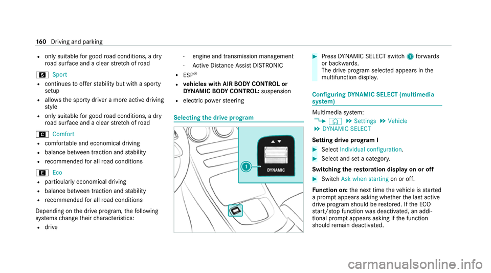
the drive prog ram #
Press DYNA MIC SELECT switch 1forw ards
or backwards.
The drive prog ram selected appears in the
multifunction displa y. Configuring
DYNA MIC SELECT (multimedia
sy stem) Multimedia sy
stem:
4 © 5
Settings 5
Vehicle
5 DYNAMIC SELECT
Setting drive prog ram I #
Select Individual configuration. #
Select and set a categor y.
Switching there storation display on or off #
Swit chAsk when starting on or off.
Fu nction on: the next time theve hicle is star ted
a prom ptappears asking whe ther the last active
drive prog ram should be restored. If the ECO
st art/ stop function was deactivated, an addi‐
tional prom ptappears asking if the function
should remain deactivated. 16 0
Driving and pa rking
Page 217 of 469
R
Ifth e lane markings change quickl y,e.g.
lanes branch off, cross one ano ther or
mer ge.
R Ifth e car riag ewa y is very nar row and wind‐
ing.
R Vehicles with Driving Assistance Pack‐
age: ifth era dar sensors in there ar bumper
are dirty or co vered in snow and an obs tacle
is de tected in your lane, no lane-cor recting
brake application take s place.
Ac tivating/deactivating Active Lane Keeping
Assist
Multimedia sy stem:
4 © 5
Settings 5
Quick access
5 Active Lane Keeping Assist #
Activate or deacti vate the function. Setting
Active Lane Keeping Assist
Multimedia sy stem:
4 © 5
Settings 5
Assistance
5 Active Lane Keeping Assist
Setting the sensitivity
% The availability of this function is dependent
on the count ry. #
Select Standard ,Sensitive orOff.
Ac tivating or deactivating the haptic warning #
Select Warning.
Ac tivate or deacti vate the function. DY
NA MIC BODY CONT ROL function DY
NA MIC BODY CONTROL continuously adjusts
th ech aracteristics of the suspension dampers to
th e cur rent operating and driving conditions.
The da mping is tuned individually for each wheel
and is af fected bythefo llowing factors:
R The road sur face conditions
R Vehicle load
R The drive program selected R
The driving style
The drive program can be adjus ted using the
DY NA MIC SELECT switch. AIR
BODY CONT ROL AIR
BODY CONT ROL function
* NO
TEMercedes-AMG vehicles #
Obser vethe no tes in the Supplement.
Yo u could otherwise failto recognise
dangers. AIR BODY
CONTROL is an air suspension sy stem
with variable damping for impr oved driving com‐
fo rt. The all-round le vel control sy stem ensures
th e best possible suspension and const ant
ground clearance, even wi tha laden vehicle.
When driving at speed, theve hicle is lo wered
automatically toimpr ovedriving saf ety and to
re duce fuel consum ption. You also ha vethe
option of manually adjusting theve hicle le vel. 214
Driving and pa rking
Page 218 of 469
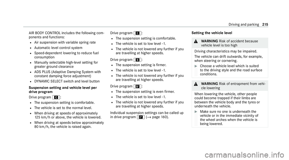
AIR BODY
CONTROL includes thefo llowing com‐
ponents and functions:
R Air suspension with variable spring rate
R Automatic le vel control sy stem
R Speed-dependent lo wering toreduce fuel
consum ption
R Manually selec table high-le vel setting for
grea ter ground clea rance
R ADS PLUS (Ada ptive Damping Sy stem with
const ant damping forc e adjustment)
R DYNA MIC SELECT switch and le vel button
Suspension setting and vehicle le vel per
drive prog ram
Drive program A:
R The suspension setting is comfor table.
R The vehicle is set tothe normal le vel.
R When driving at speeds of appr oximately
12 5 km/h or abo ve,th eve hicle is lo wered.
R When driving at speeds below appr oximately
80 km/h, theve hicle is raised again. Drive program
;:
R The suspension setting is com fortable.
R The vehicle is set tolow le vel -1.
R The vehicle is not lo wered any fur ther if you
are tr avelling at higher speeds.
Drive prog ram C:
R The suspension setting is firm er.
R The vehicle is set tolow le vel -1.
R The vehicle is not lo wered any fur ther if you
are tra velling at higher speeds.
Drive prog ram B:
R The suspension setting is evenfirm er.
R The vehicle is set tolow le vel -1.
R The vehicle is not lo wered any fur ther if you
are tra velling at higher speeds.
Individual suspension settings can be called up
in drive prog ram = (/page 160). Se
tting the vehicle le vel &
WARNING Risk of accident because
ve hicle le vel is too high
Driving characteristics may be impaired.
The vehicle can drift outwards, forex ample,
when steering or cornering. #
Choose a vehicle le vel which is suited
to the driving style and thero ad sur face
conditions. &
WARNING Risk of entrapment from vehi‐
cle lo wering
When lo wering theve hicle, other people
could become trapped if their limbs are
between theve hicle body and the tyres or
underneath theve hicle. #
Make sure no one is underneath the
ve hicle or in the immediate vicinity of
th e wheel ar ches when theve hicle is
being lo wered. Driving and parking
215
Page 338 of 469
R
Only fit wheels of the same size on one axle
(left and right).
It is only permissible tofit a di fferent wheel
size in theeve nt of a flat tyre in order to
drive tothe specialist workshop.
R Do not make any modifications tothe brake
sy stem, the wheels or the tyres.
The use of shims or brake dust shields is not
permitted and may in validate theve hicle's
ge neral operating pe rmit.
R Vehicles with a tyre pressure monitoring
sy stem: allfitted wheels mu stbe equipped
with functioning sensors forth e tyre pres‐
sure monitoring sy stem.
R Attemp eratures below 7 °C use winter tyres
or all-season tyres mar kedi M+Sfor all
wheels.
Wi nter tyres pr ovide the best possible grip in
wintry road conditions.
R Fori M+S tyres, only use tyres with the
same tread.
R Obser vethe maximum permissible speed for
th ei M+S tyres fitted. If
th e tyre's maximum speed is below that of
th eve hicle, this must be indicated byan
appropriate label in the driver's field of
vision.
R Run in new tyres at moderate speeds forthe
fi rs t10 0 km.
R Replace the tyres af ter six years at the latest,
re ga rdless of wear.
R When replacing with tyres that do not
fe ature run-flat characteristics: vehicles
with MOExtended tyres are not equipped
with a TIREFIT kit at thefa ctor y.Equip the
ve hicle with a TIREFIT kit af terre placing with
tyres that do not feature run-flat characteris‐
tics, e.g. winter tyres.
% You can permanently limit the maximum
ve hicle speed for driving with winter tyres
(/ page 190).
Fo r more information on wheels and tyres, con‐
ta ct a qualified specialist workshop.
Be sure toalso obse rveth efo llowing fur ther
re lated subjects:
R Notes on tyre pressure (/ page 328)R
Tyre pressure table (/ page 329)
R Notes on the emer gency spa rewheel
(/ page 342) Note
s on inter changing wheels &
WARNING Risk of inju rythro ugh dif fer‐
ent wheel sizes
Inter changing the front and rear wheels can
se verely impair the driving characteristics.
The disk brakes or wheel suspension compo‐
nents may also be damaged. #
Onlyinter change the front and rear
wheels if the wheels and tyres ha vethe
same dimensions. Inter
changing the front and rear wheels if the
wheels or tyres ha vediffere nt dimensions can
re nder thege neral operating pe rmit in valid.
The wear pat tern s on the front and rear wheels
dif fer:
R front wheels wear more on the tyre shoulder Wheels and tyres
335
Page 427 of 469
Wa
rning/indicator lamp
Possible causes/consequences and M
MSolutions
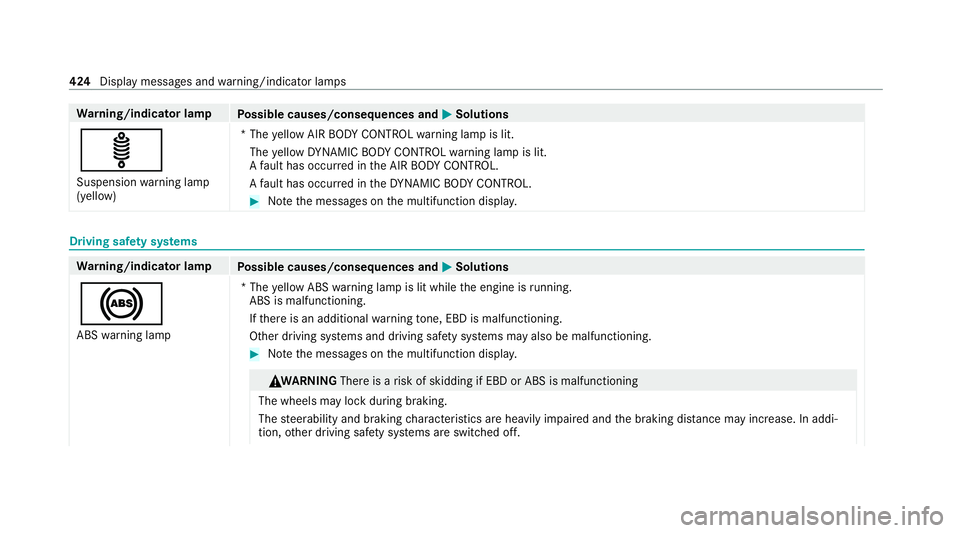
ä Suspension warning lamp
(yellow) *T
he yellow AIR BODY CONTROL warning lamp is lit.
The yellow DYNA MIC BODY CONTROL warning lamp is lit.
A fault has occur red in the AIR BODY CONTROL.
A fault has occur red in theDY NA MIC BODY CONTROL. #
Notethe messages on the multifunction displa y.Driving saf
ety sy stems Wa
rning/indicator lamp
Possible causes/consequences and M
MSolutions
! ABS warning lamp *T
he yellow ABS warning lamp is lit while the engine is running.
ABS is malfunctioning.
If th ere is an additional warning tone, EBD is malfunctioning.
Other driving sy stems and driving saf ety sy stems may also be malfunctioning. #
Notethe messages on the multifunction displa y. &
WA RNING Thereis a risk of skidding if EBD or ABS is malfunctioning
The wheels may lock during braking.
The steerability and braking characteristics are heavily impaired and the braking dis tance may increase. In addi‐
tion, other driving saf ety sy stems are switched off. 424
Display messages and warning/indicator lamps
Page 433 of 469
Ac
tive Parking Assist .............................. 229
Exiting a parking space ...................... .232
Fu nction .............................................. 229
Pa rking ................................................ 230
Sy stem limitations ...............................2 29
Ac tive Se rvice Sy stem PLUS
see AS SYST PLUS
Ac tive Speed Limit Assi st....................... 194
Displ ay................................................. 194
Fu nction .............................................. 194
Ac tive Steering Assist ............................ .197
Ac tivating/deactivating ...................... .199
Ac tive Emergency Stop Assist .............1 99
Fu nction .............................................. 197
Sy stem limits ....................................... 197
Ac tive Traf fic Jam Assist
Ac tivating/deactivating ...................... .197
Fu nction .............................................. 197
Ad aptive brake lights ..............................185
Ad aptive cruise control
see Active Dis tance Assi stDISTRONIC
Ad aptive Highbeam Assist
Fu nction .............................................. 12 5Switching on/off .................................
12 6
Ad aptive Highbeam Assist Plus
Fu nction .............................................. 12 6
Switching on/off ................................. 12 8
Ad Blue ®
.................................................... 352
Ad ditives .............................................3 52
Capacity .............................................. 352
No tes ................................................... 16 9
Purity ................................................... 352
To pping up ...........................................1 70
Ad ditional door lo ck.................................. 74
Ad diti ves.................................................. 353
Ad Blue ®
............................................... 352
Engine oil ............................................ 353
Fu el ..................................................... 350
Ad diti ves (AdBlue ®
)
see AdBlue ®
Ad diti ves (engine oil)
see Additives
Ad diti ves (fuel)
see Fuel
ADS PLUS damping sy stem
see AIR BODY CONTROL Ad
versewe ather light ............................ .125
Af ter-sales service centre
see ASS YST PLUS
AIR BODY CONT ROL................................ .214
Setting ................................................. 215
Suspension .......................................... 214
Air conditioning menu Calling up ............................................ 13 8
Air distribution Setting ................................................ .137
Setting (MBUX multimedia sy stem) ..... 13 9
Air freshener sy stem
see Frag rance sy stem
Air inlet see Air-water duct
Air pressure see Tyre pressure
Air suspension see AIR BODY CONTROL
Air vents ................................................... 14 6
Ad justing (front) .................................. 14 6
Ad justing (rear) .................................... 147430
Index
Page 459 of 469
St
eering wheel heater .......................... 103
Ste ering wheel gearshift paddles ..........16 4
Ste ering wheel heater
Swit ching on/off ................................ .103
St ow age areas
see Loading
see Stow age compartment
St ow age comp artment........................... 109
Armrest ............................................... 109
Centre console .................................... 109
Door .................................................... 109
Glo vecompa rtment ............................. 109
St ow age comp artments
see Loading
see Stow age compartment
St ow age spaces
USB ports ............................................ 109
Suggestions Configuring .......................................... 258
Sulphur content ...................................... 349
Sur round lighting
Switching on/off ................................. 12 8Sur
round View
see 360° Camera
Suspension Adjusting thech assis le vel (AIR
BO DY CONTROL) .................................2 15
Suspension see AIR BODY CONTROL
SV HC (substances of very high con‐
cern ).......................................................... .30
Switch-off delay time Exterior ................................................ 12 8
Interior ................................................. 13 0
Synchronisation function Activating/deactivating (MBUX mul‐
timedia sy stem) ................................... 13 9
Switching on/off (control panel) ......... 13 9
Sy stem settings
Overview of the sy stem settings
menu ................................................... 258 T
Ta ilpipes (care) ........................................ 302 Ta
ke -back of end-of-life vehicles .............. 20
Pr otection of the environment ............... 20
Ta nk content
Ad Blue ®
............................................... 352
Fu el ...................................................... 351
Re ser ve(fuel) .......................................3 51
Te ch nical data
Axle load (trailer operation) ................. 359
Fa stening points (trailer hitch) .............3 58
Information .......................................... 343
Mounting dimensions (trailer hitch) ..... 358
No tes (trailer hitch) ............................. 357
Overhang dimension (trailer hitch) ...... 358
Ra dio operating permits ...................... 345
To ngue weight .................................... .358
To wing capacity (trailer operation) ...... 358
Te lephone ........................................ 268, 270
Connecting a mobile phone (Pass‐
ke y) ...................................................... 271
Connecting a mobile phone (Secure
Simple Pairing) .................................... 271
Fu nctions in thete lephone menu ........ 271
No tes .................................................. 268
Operating modes ................................. 270
Te lephone menu overview ...................2 70456
Index
Page 463 of 469
Ve
hicle maintenance
see ASS YST PLUS
Ve hicle tool kit ........................................ .310
TIREFIT kit ............................................ 310
To wing eye .......................................... 323
Ve ntilating
Con venience opening ............................ 85
Ve ntilation
see Climate cont rol
Ve nts
see Air vents
VIN ............................................................ 345
Identification plate .............................. 345
Seat ..................................................... 345
Wi ndsc reen ......................................... 345
Vi sion
Demisting windo ws............................. 14 0
Wi ndsc reen heating ............................. 14 2W
Wa rning lamps
see Warning/indicator lamps Wa
rning sy stem
see ATA (anti-theft alarm sy stem)
Wa rning triangle
Re moving ............................................ 306
Setting up ............................................ 307
Wa rning/indicator lamp
! ABSwarning lamp ...................... 424
æ Active Brake Assi stwa rning
lamp .................................................... 423
J Brake sy stem warning lamp
(red) .................................................... 422
J Brake sy stem warning lamp
(yellow) ................................................ 421
ÿ Coolant warning lamp (red) ........ .418
ÿ Coolant warning lamp (yellow) .... 419
! Electric pa rking brake indicator
lamp (red) ............................................ 421
# Electrical fault warning lamp ...... 420
; Engine diagnosis warning lamp .. .419
å ESP®
OFF warning lamp ............ .426
÷ ESP®
wa rning lamp flashes ........ 425 ÷
ESP®
wa rning lamp lights up ...... 425
8 Fuelreser vewarning lamp
lights up .............................................. 420
Ù Powe rst eering warning lamp
(red) .................................................... .416
6 Restra int sy stem warning lamp .. .415
ü Seat belt warning lamp flashes .. .415
ü Seat belt warning lamp lights
up ........................................................ 416
ä Suspension warning lamp (yel‐
low) .................................................... .424
! The electric parking brake (yel‐
low) indicator lamp .............................. 421
ï Trailer tow hit chwarning lamp .... 417
h Tyre pressure monitoring sys‐
te m wa rning lamp flashes .................. .427
h Tyre pressure monitoring sys‐
te m wa rning lamp lights up ................ .427
L Warning lamp for dis tance
wa rning function ................................ .423 460
Index