light MERCEDES-BENZ CLS SHOOTING BRAKE 2012 User Guide
[x] Cancel search | Manufacturer: MERCEDES-BENZ, Model Year: 2012, Model line: CLS SHOOTING BRAKE, Model: MERCEDES-BENZ CLS SHOOTING BRAKE 2012Pages: 405, PDF Size: 10.21 MB
Page 22 of 405
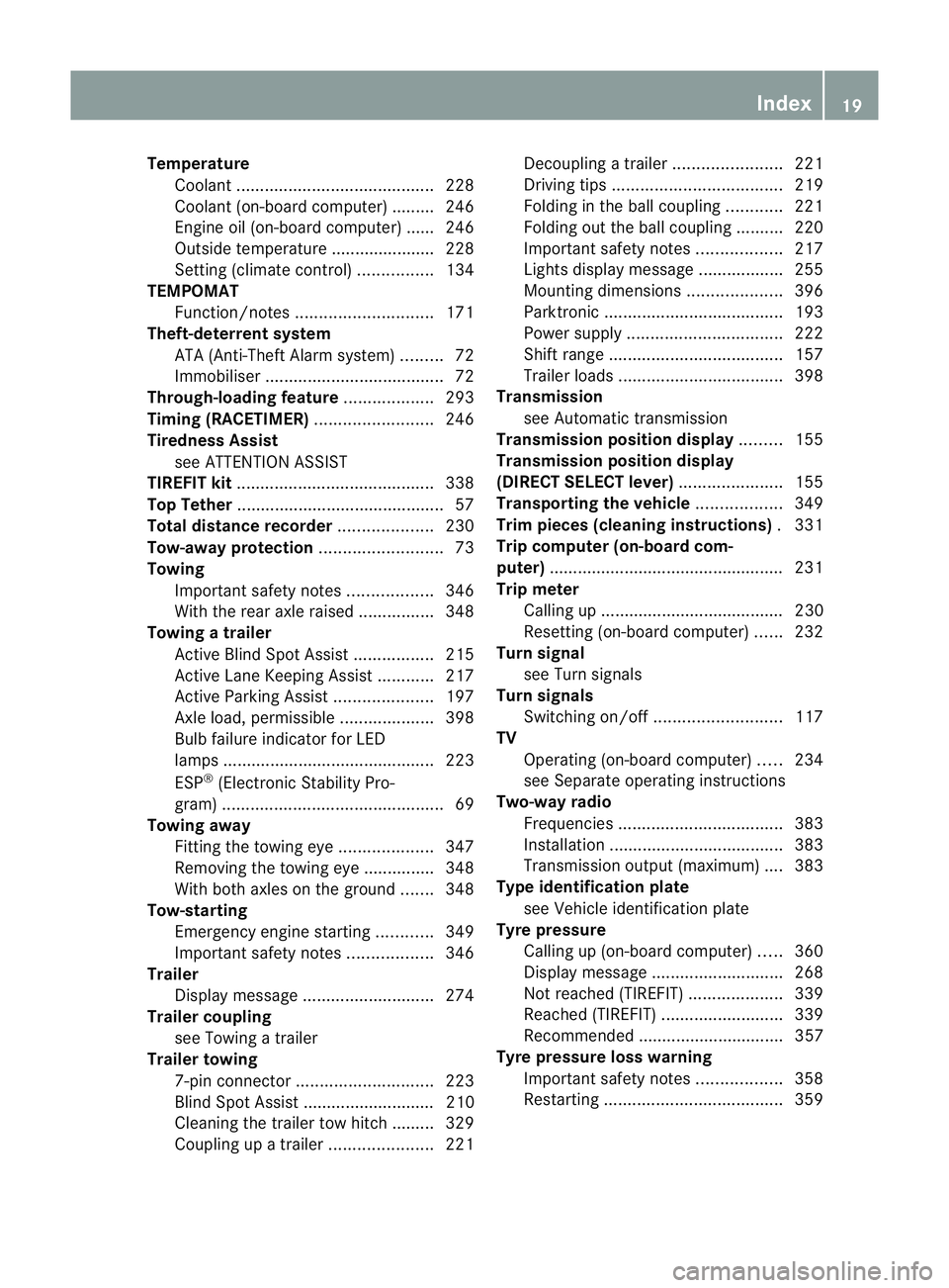
Temperature
Coolant .......................................... 228
Coolant (on-board computer) ......... 246
Engine oil (on-board computer) ...... 246
Outside temperature ..................... .228
Setting (climate control) ................134
TEMPOMAT
Function/notes ............................. 171
Theft-deterrent system
ATA (Anti-Theft Alarm system) .........72
Immobiliser ...................................... 72
Through-loading feature ...................293
Timing (RACETIMER) .........................246
Tiredness Assist see ATTENTION ASSIST
TIREFIT kit .......................................... 338
Top Tether ............................................ 57
Total distance recorder ....................230
Tow-away protection ..........................73
Towing Important safety notes ..................346
With the rear axle raised ................348
Towing atrailer
Activ eBlind Spot Assist .................215
Active Lane Keeping Assist ............217
Active Parking Assist .....................197
Axle load, permissible ....................398
Bulb failure indicator for LED
lamps ............................................. 223
ESP ®
(Electroni cStability Pro-
gram) ............................................... 69
Towing away
Fitting the towing eye. ...................347
Removing the towing eye. ..............348
With both axles on the ground .......348
Tow-starting
Emergency engine starting ............349
Important safety notes ..................346
Trailer
Display message ............................ 274
Trailer coupling
see Towing atrailer
Trailer towing
7-pin connector ............................. 223
Blind Spot Assist ............................ 210
Cleaning the trailer tow hitch ......... 329
Coupling up atrailer ...................... 221Decoupling
atrailer ....................... 221
Driving tips .................................... 219
Folding in the ball coupling ............221
Folding out the ball coupling ..........220
Important safety notes ..................217
Lights displa ymessage .................. 255
Mounting dimensions ....................396
Parktroni c...................................... 193
Power supply ................................. 222
Shift range ..................................... 157
Trailer loads ................................... 398
Transmission
see Automatic transmission
Transmission position display .........155
Transmission position display
(DIRECT SELECTl ever)...................... 155
Transporting the vehicle ..................349
Trim pieces (cleaning instructions) .331
Trip computer (on-board com-
puter) ................................................. .231
Trip meter Calling up ....................................... 230
Resetting (on-board computer) ......232
Turn signal
see Turn signals
Turn signals
Switching on/off ........................... 117
TV
Operating (on-board computer) .....234
see Separate operating instructions
Two-way radio
Frequencies ................................... 383
Installatio n..................................... 383
Transmission output (maximum) .... 383
Type identification plate
see Vehicle identification plate
Tyre pressure
Calling up (on-board computer) .....360
Display message ............................ 268
Not reached (TIREFIT) ....................339
Reached (TIREFIT) ..........................339
Recommended ............................... 357
Tyre pressure loss warning
Important safety notes ..................358
Restarting ...................................... 359 Index
19
Page 33 of 405
Instrumen
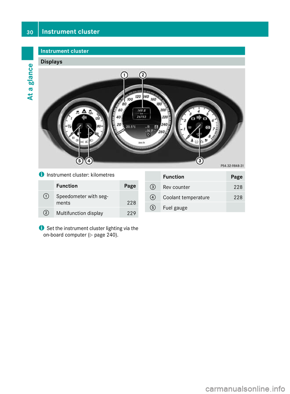
tcluster Displays
i
Instrument cluster: kilometres Function Page
:
Speedometer with seg-
ments
228
;
Multifunction display
229 Function Page
=
Rev counter 228
?
Coolant temperature 228
A
Fuel gauge
i
Set the instrumen tcluster lighting via the
on-board computer (Y page 240).30
Instrument clusterAt a glance
Page 34 of 405
i
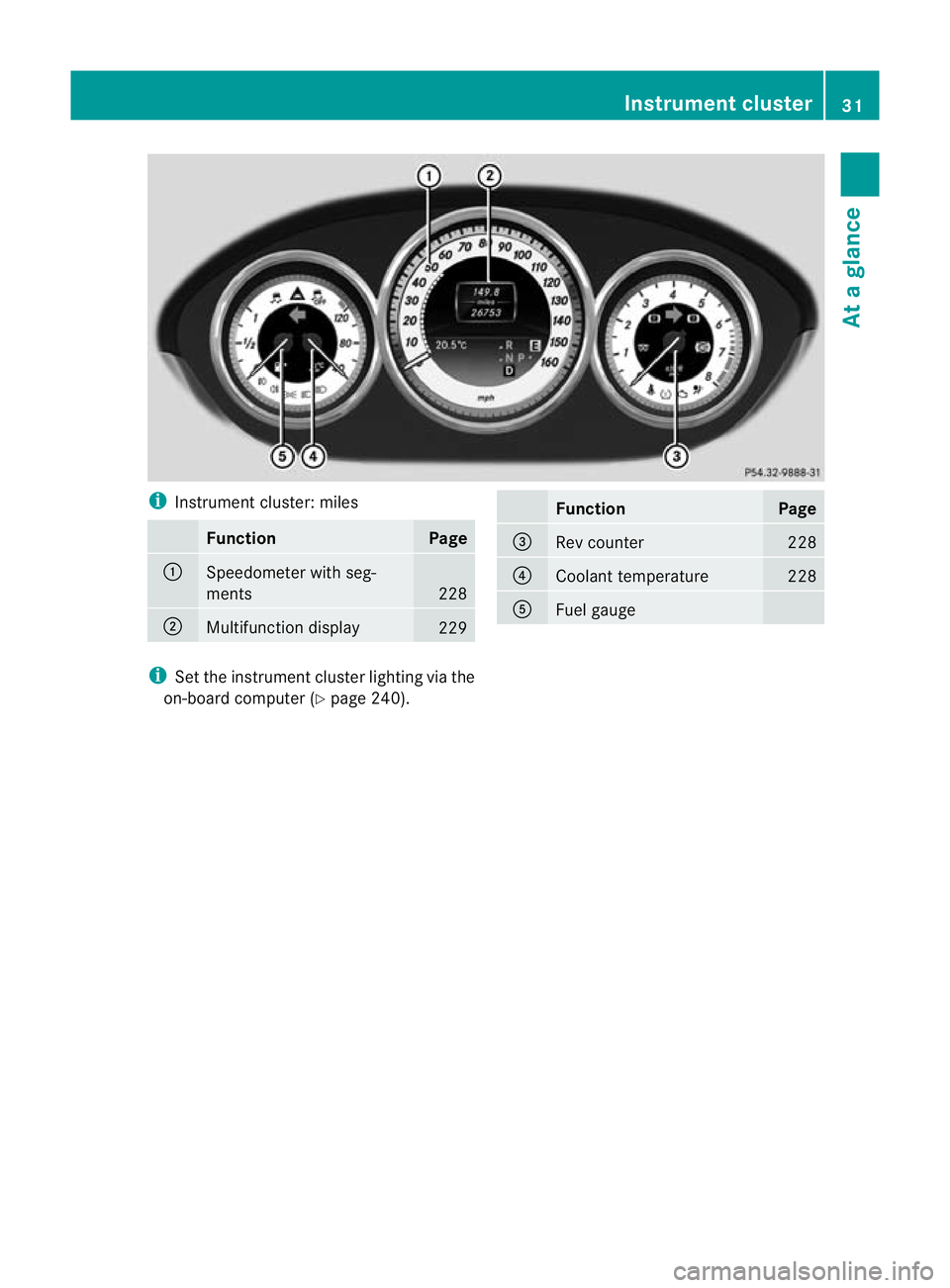
Instrument cluster: miles Function Page
:
Speedometer with seg-
ments
228
;
Multifunction display
229 Function Page
=
Rev counter 228
?
Coolant temperature 228
A
Fuel gauge
i
Set the instrument cluster lighting via the
on-board computer (Y page 240). Instrument cluster
31At a glance
Page 38 of 405
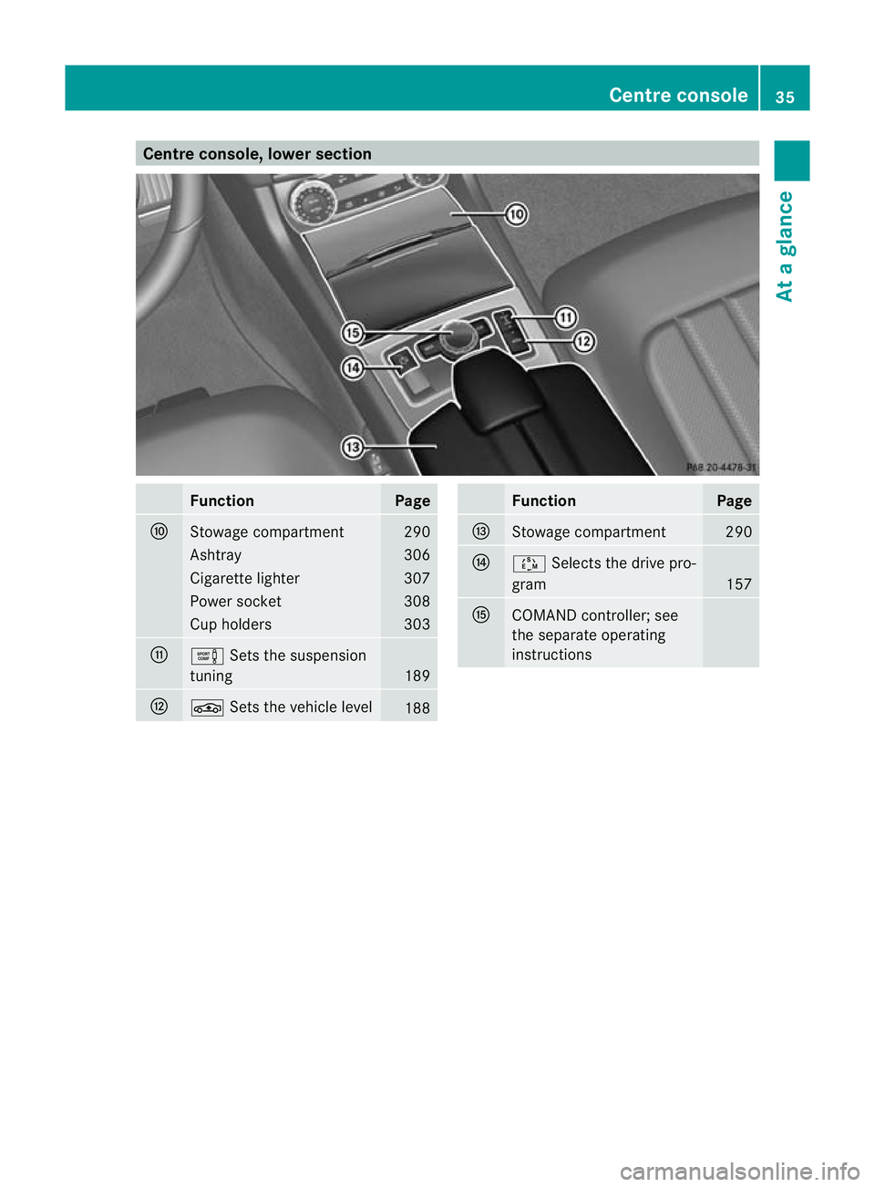
Centre console, lower section
Function Page
F
Stowage compartment 290
Ashtray 306
Cigarette lighter 307
Power socket 308
Cup holders 303
G
e
Sets the suspension
tuning 189
H
É
Sets the vehicle level 188 Function Page
I
Stowage compartment 290
J
Ú
Selects the drive pro-
gram 157
K
COMAND controller; see
the separate operating
instructions Centre console
35At a glance
Page 39 of 405
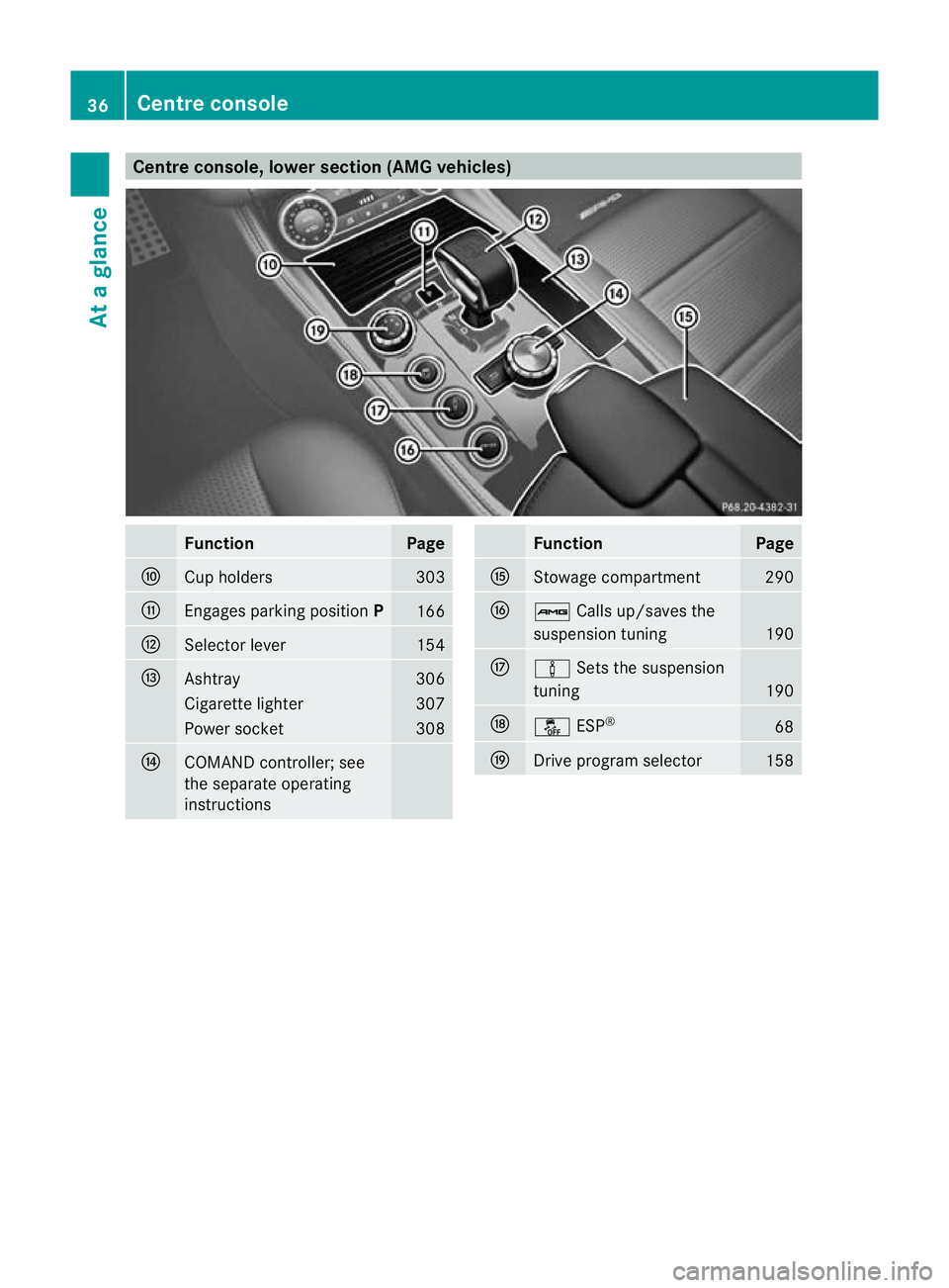
Centre console, lower section (AMG vehicles)
Function Page
F
Cup holders 303
G
Engages parking position
P 166
H
Selector lever 154
I
Ashtray 306
Cigarette lighter 307
Power socket 308
J
COMAND controller; see
the separate operating
instructions Function Page
K
Stowage compartment 290
L
ß
Calls up/saves the
suspension tuning 190
M
à
Sets the suspension
tuning 190
N
å
ESP® 68
O
Drive program selector 15836
Centre consoleAt a glance
Page 40 of 405
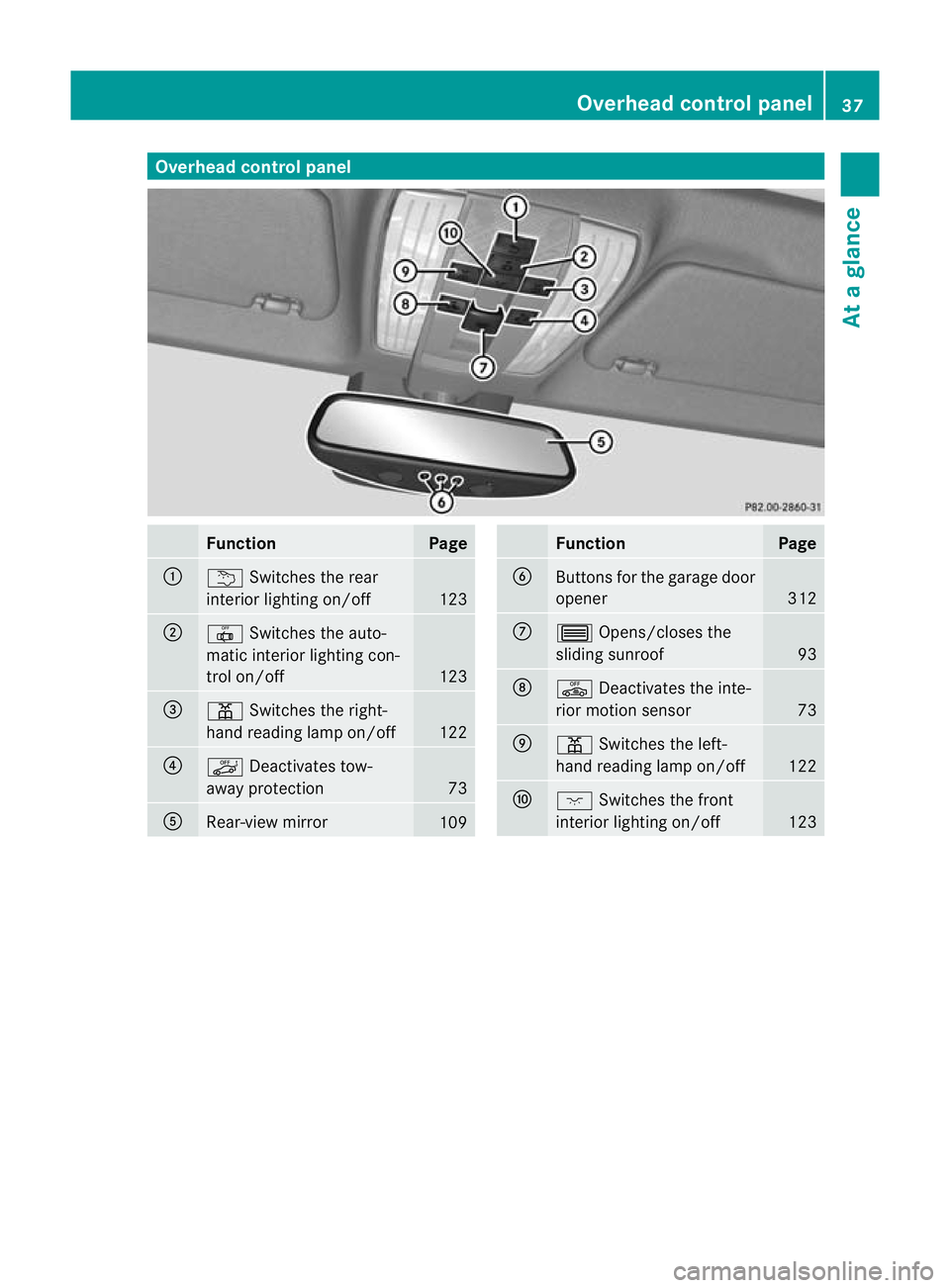
Overhea
dcontrol panel Function Page
:
u
Switches the rear
interio rlighting on/off 123
;
|
Switches the auto-
matic interior lighting con-
trol on/off 123
=
p
Switches the right-
hand reading lamp on/off 122
?
ë
Deactivates tow-
away protection 73
A
Rear-view mirror
109 Function Page
B
Buttons for the garage door
opener
312
C
3
Opens/closes the
sliding sunroof 93
D
ê
Deactivates the inte-
rior motion sensor 73
E
p
Switches the left-
hand reading lamp on/off 122
F
c
Switches the front
interior lighting on/off 123Overhead control panel
37At a glance
Page 43 of 405
Useful information
i This Owner's Manual describes all mod-
els, series and optional equipment for your
vehicle that were available at the time of
going to press. National variations are pos-
sible. Note that your vehicle may not be
equipped with all of the functions descri-
bed. This is also the case for systems and
functions relevant to safety.
i Read the information on qualified special-
ist workshops: (Y page 24). Panic alarm
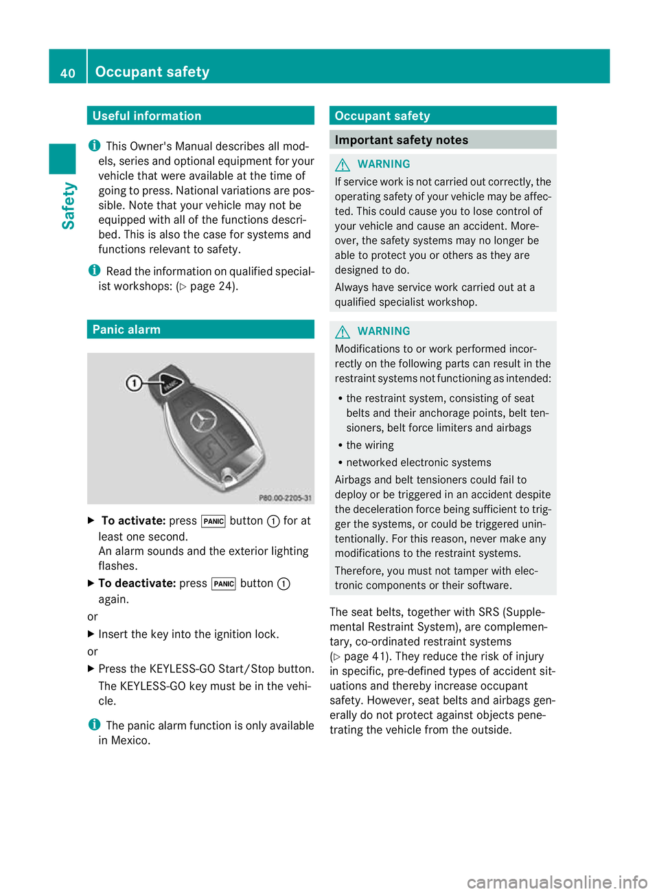
X
To activate: press!button :for at
least one second.
An alarm sounds and the exterior lighting
flashes.
X To deactivate: press!button :
again.
or
X Insert the key into the ignition lock.
or
X Press the KEYLESS-GO Start/Stop button.
The KEYLESS-GO key must be in the vehi-
cle.
i The panic alarm function is only available
in Mexico. Occupant safety
Important safety notes
G
WARNING
If service work is not carried out correctly, the
operating safety of your vehicle may be affec-
ted. This could cause you to lose control of
your vehicle and cause an accident. More-
over, the safety system smay no longer be
able to protect you or others as they are
designed to do.
Always have service work carried out at a
qualified specialist workshop. G
WARNING
Modifications to or work performed incor-
rectly on the following parts can result in the
restraint systems no tfunctioning as intended:
R the restraint system, consisting of seat
belts and their anchorage points, belt ten-
sioners, belt force limiters and airbags
R the wiring
R networked electronic systems
Airbags and belt tensioners could fail to
deploy or be triggered in an acciden tdespite
the deceleration force being sufficien tto trig-
ger the systems, or could be triggered unin-
tentionally. For this reason, never make any
modifications to the restraint systems.
Therefore, you must not tamper with elec-
tronic components or their software.
The seat belts, together with SRS (Supple-
mental Restraint System), are complemen-
tary, co-ordinated restraint systems
(Y page 41). They reduce the risk of injury
in specific, pre-defined types of accident sit-
uations and thereby increase occupant
safety. However, seat belts and airbags gen-
erally do not protect against objects pene-
trating the vehicle from the outside. 40
Occupant safetySafety
Page 44 of 405
To ensure that the restraint systems can
deliver their full potential protection, make
sure that:
R the seat and head restraint are adjusted
properly (Y page 98).
R the seat belt has been fastened properly
(Y page 49).
R the airbags can inflate unrestricted if
deployed (Y page 42).
R the steering wheel is adjusted properly
(Y page 105).
R the restraint systems have not been modi-
fied.
An airbag increases the protection of vehicle
occupants wearing a seat belt. However, air-
bags are only an additional restraint system
which complements, but does not replace,
the seat belt. All vehicle occupants must wear
their seat belt correctly at all times, even if
the vehicle is equipped with airbags. The air-
bags are not deployed in all types of acci-
dents .For example, if the protective capacity
of correctly fastened seat belts is not
increased by deploying the airbags, the air-
bags will not deploy.
Airbag deployment only provides increased
protection if the seat belt is worn correctly.
First, the seat belt helps to keep the vehicle
occupant in the best position in relation to the
airbag. Second, in a head-on collision, for
example, the seat belt prevents the vehicle
occupant from being propelled towards the
point of impact. SRS (Supplemental Restraint System)
Introduction SRS consists of:
R
the 6 SRS warning lamp
R airbags
R the airbag control unit with crash sensors
R belt tensioners
R belt force limiters SRS reduces the risk of occupants coming
into contact with the vehicle's interior in the
event of an accident. It can also reduce the
forces to which occupant
sare subjected dur-
ing an accident.
SRS warning lamp G
WARNING
If SRS is malfunctioning, individual systems
may be triggered unintentionally or might not
be triggered in the event of an accident with
a high rate of vehicle deceleration.
A malfunction has occurred if:
R the 6 SRS warning lamp does not light
up when the ignitio nis switched on.
R the engine is running and the 6SRS
warning lamp does not go out after a few
seconds.
R the engine is running and the 6SRS
warning lamp lights up again.
In this case, have SRS checked immediately
at a qualified specialist workshop.
SRS functions are checked regularly when
you switch on the ignition and when the
engine is running. Therefore, malfunctions
can be detected in good time.
The 6 SRS warning lamp in the instrument
cluster lights up when the ignition is switched
on. It goes out no later than a few seconds
after the engine is started.
Triggering of belt tensioners, belt force
limiters and airbags During the first stage of a collision, the airbag
control unit evaluates important physical
data relating to vehicle deceleration or accel-
eration, such as:
R
duration
R direction
R magnitude
Based on the evaluation of this data, the air-
bag control unit pre-emptively triggers the
belt tensioners in the first stage. Occupant safety
41Safety Z
Page 47 of 405
Have the airbags replaced at a qualified spe-
cialist workshop
.Otherwise, occupants are
not protected by the airbags in the event of
another accident.
Airbag deployment slows down and restricts
the movement of the vehicle occupant.
If the airbags are deployed ,you will hear a
bang and a small amount of powder may also
be released. Only in rare cases will the bang
affect your hearing. The powder that is
released generally does not constitute a
health hazard. The 6SRS warning lamp
lights up.
The airbag installation locations are identified
by the AIRBAG symbol.
Front airbags !
Do not place heavy objects on the front-
passenger seat. The system may then
detect that the seat is occupied and if there
is an accident, the restraint systems on the
front-passenger side could be deployed.
Have restraint systems that have been trig-
gered replaced. Driver's airbag
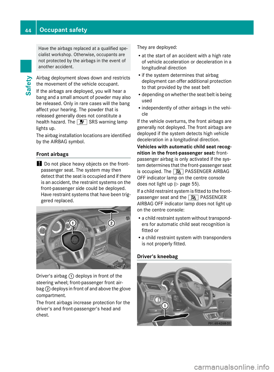
:deploys in front of the
steering wheel; front-passenger front air-
bag ;deploys in front of and above the glove
compartment.
The front airbags increase protection for the
driver's and front-passenger's head and
chest. They are deployed:
R
at the start of an accident with a high rate
of vehicle acceleration or deceleration in a
longitudinal direction
R if the system determines that airbag
deployment can offer additional protection
to that provided by the seat belt
R depending on whether the seat belt is being
used
R independently of other airbags in the vehi-
cle
If the vehicle overturns, the front airbags are
generally not deployed. The front airbags are
deployed if the system detects high vehicle
deceleration in a longitudinal direction.
Vehicles with automatic child seat recog-
nition in the front-passenger seat: front-
passenger airbag is only activated if the sys-
tem determines that the front-passenger seat
is occupied. The 4PASSENGER AIRBAG
OFF indicator lamp on the centre console
does not light up (Y page 55).
If a child restraint system is fitted to the front-
passenger seat and the 4PASSENGER
AIRBAG OFF indicator lamp does not light up
on the centre console:
R a child restraint system without transpond-
ers for automatic child seat recognition is
fitted or
R a child restraint system with transponders
is not properly fitted.
Driver's kneebag 44
Occupant safetySafety
Page 51 of 405
NECK-PRO luxury head restraints
NECK-PRO luxury head restraints (example: CLS
Coupé)
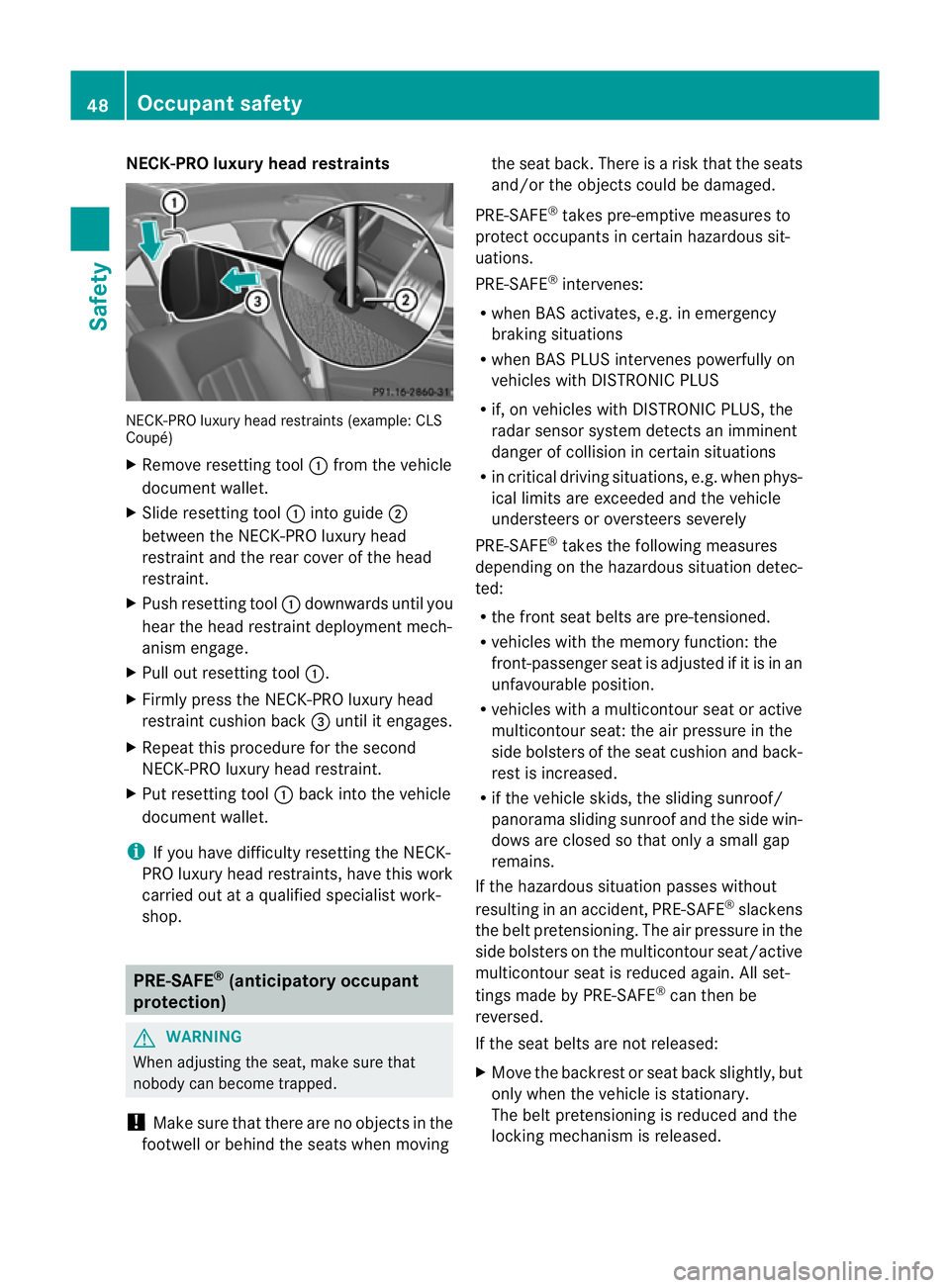
X
Remove resetting tool :from the vehicle
document wallet.
X Slide resetting tool :into guide ;
between the NECK-PRO luxury head
restraint and the rear cover of the head
restraint.
X Push resetting tool :downwards until you
hear the head restraint deployment mech-
anism engage.
X Pull ou tresetting tool :.
X Firmly press the NECK-PRO luxury head
restraint cushion back =until it engages.
X Repeat this procedure for the second
NECK-PRO luxury head restraint.
X Put resetting tool :back into the vehicle
documen twallet.
i If you have difficulty resetting the NECK-
PRO luxury head restraints, have this work
carried out at a qualified specialist work-
shop. PRE-SAFE
®
(anticipatory occupant
protection) G
WARNING
When adjusting the seat, make sure that
nobody can become trapped.
! Make sure that there are no objects in the
footwell or behind the seats when moving the seat back
.There is a risk that the seats
and/or the objects could be damaged.
PRE-SAFE ®
takes pre-emptive measures to
protect occupants in certain hazardous sit-
uations.
PRE-SAFE ®
intervenes:
R when BAS activates, e.g. in emergency
braking situations
R when BAS PLUS intervenes powerfully on
vehicles with DISTRONIC PLUS
R if, on vehicles with DISTRONIC PLUS, the
radar sensor system detectsani mminent
dange rofcollision in certain situations
R in critical driving situations, e.g. when phys-
ical limits are exceeded and the vehicle
understeers or oversteers severely
PRE-SAFE ®
takes the following measures
depending on the hazardous situation detec-
ted:
R the front seat belts are pre-tensioned.
R vehicles with the memory function: the
front-passenger seat is adjusted if it is in an
unfavourable position.
R vehicles with a multicontour seat or active
multicontour seat: the air pressure in the
side bolsters of the seat cushion and back-
rest is increased.
R if the vehicle skids, the sliding sunroof/
panorama sliding sunroof and the side win-
dows are closed so that only a small gap
remains.
If the hazardous situation passes without
resulting in an accident, PRE-SAFE ®
slackens
the belt pretensioning. The air pressure in the
side bolsters on the multicontour seat/active
multicontour seat is reduced again. All set-
tings made by PRE-SAFE ®
can then be
reversed.
If the seat belts are not released:
X Move the backrest or seat back slightly, but
only when the vehicle is stationary.
The belt pretensioning is reduced and the
locking mechanism is released. 48
Occupant safetySafety