instrument panel MERCEDES-BENZ CLS SHOOTING BRAKE 2012 Owners Manual
[x] Cancel search | Manufacturer: MERCEDES-BENZ, Model Year: 2012, Model line: CLS SHOOTING BRAKE, Model: MERCEDES-BENZ CLS SHOOTING BRAKE 2012Pages: 405, PDF Size: 10.21 MB
Page 10 of 405
Centre console
Lowe rsection .................................. 35
Lowe rsection (AMG vehicles) ..........36
Uppe rsection .................................. 34
Changing bulbs
Important safety notes ..................123
Overview of bul btypes .................. 124
Reversing lamps ............................ 124
Child-proof locks
Important safety notes ....................63
Rea rdoors ....................................... 63
Children
In the vehicle ................................... 53
Restraint systems ............................ 53
Child seat
Automatic recognition .....................55
ISOFIX .............................................. 56
On the front-passenger sea t............ 54
Problem (malfunction) .....................59
Recommendations ...........................61
Suitable positions ............................ 59
Top Tether ....................................... 57
Cigarette lighter ................................ 307
Cleaning Mirro rturn signal ........................... 328
Trailer tow hitch ............................. 329
Climate control
Auxiliary heating/ventilation .......... 138
Controlling automatically ...............134
Convenience opening/closing
(air-recirculatio nmode) ................. 137
Cooling with aird ehumidification..133
Demisting the windows .................. 136
Demisting the windscreen .............136
Important safety notes ..................130
Indicator lamp ................................ 134
Information on using
THERMOTRONIC automatic cli-
mate control .................................. 133
Notes on using THERMATIC auto-
matic climate control .....................131
Overview of systems ......................130
Problems with cooling with air
dehumidification ............................ 134
Problem with the rear window
heating .......................................... 137
Rea rcontrol panel ......................... 132
Setting the aird istribution.............135 Setting the airflow
.........................135
Setting the airv ents...................... 142
Setting the climate mode (AIR
FLOW) ............................................ 134
Setting the temperature ................134
Setting the temperature,
THERMATI C................................... 134
Setting the temperature,
THERMOTRONIC ............................ 135
Switching air-recirculation mode
on/off ............................................ 137
Switching on/off ........................... 133
Switching residual hea ton/off ......138
Switching the rear window heat-
ing on/off ...................................... 137
Switching the ZONE function on/
off .................................................. 136
THERMATIC automatic climate
control (2-zone) ............................. 131
THERMOTRONIC (3-zone) auto-
matic climate control .....................132
Coat hooks ......................................... 296
Cockpit Overview .......................................... 28
see Instrument cluster
Collapsible emergency spare
wheel
see Emergency spare wheel
COMAND display
Cleaning ......................................... 330
COMAND Online
see separate operating instructions
Combination switch ..........................117
Consumption statistics (on-board
computer) .......................................... 231
Convenience box ............................... 299
Convenience closing feature ..............90
Convenience opening/closing (air-
recirculation mode) ........................... 137
Convenience opening feature ............90
Coolan t(engine)
Checkin gthe level ......................... 323
Display message ............................ 259
Important safety notes ..................392
Temperature (on-board computer) .246
Temperature gauge ........................ 228
Warning lamp ................................. 285 Index
7
Page 18 of 405
Instrument cluster submenu
..........239
Ligh tsubmenu ............................... 240
Menu overview .............................. 230
Message memory .......................... 249
Navigation menu ............................ 232
Operating the TV ............................ 234
Operating vide oDVD ..................... 234
Operation ....................................... 228
RACETIMER ................................... 246
Service menu ................................. 239
Settings menu ............................... 239
Standard displa y............................ 230
Telephone menu ............................ 235
Trip menu ...................................... 230
Vehicle submenu ........................... 242
Operating system
see On-board computer
Outside temperature display ...........228
Overhead control panel ......................37
Override feature Rea rside windows ........................... 63 P
Pain tcode .......................................... 384
Paintwork (cleaning instructions) ...327
Panic alarm .......................................... 40
Parking ............................................... 165
Important safety notes ..................165
Parking brake ................................ 166
Position of exterior mirror, front-
passenger side ............................... 110
Reversing camera ..........................198
see PARKTRONIC
Parking aid
Active Parking Assist .....................194
see Exterior mirrors
see PARKTRONIC
Parking brake
Display message ............................ 252
Notes/function .............................. 166
Warning lamp ................................. 284
Parking lamps
Display message ............................ 257
Switching on/off ........................... 117
PARKTRONIC
Deactivating/activating .................193
Driving system ............................... 191Function/notes
............................. 191
Important safety notes ..................191
Problem (fault) ............................... 194
Sensor range ................................. 192
Trailer towing ................................. 193
Warning displa y............................. 193
PASSENGE RAIRBAG OFF warning
lamp ...................................................... 55
Petrol .................................................. 387
Plastic trim (cleaning instructions) .330
Power windows see Side windows
PRE-SAFE ®
(preventive occupant
safety system) Display message ............................ 253
Operation ........................................ .48
PRE-SAFE ®
Brake
Activating/deactivating .................237
Display message ............................ 253
Function/notes ................................ 70
Warning lamp ................................. 287
Product information ............................22
Program selector button ..................157
Protection of the environment General notes .................................. 22
Pulling away (automatic transmis-
sion) .................................................... 149 Q
Qualifie dspecialis tworkshop ...........24 R
RACE START (AMG vehicles) .............187
RACETIMER (on-board computer) ....246
Radar sensors Overview ........................................ 398
Radar sensor system
Activating/deactivating .................243
Display message ............................ 263
Radiator cover ................................... 321
Radio Selecting astation ......................... 233
see separate operating instructions
Rain closing feature (slidin gsun-
roof) ...................................................... 93
Reading lamp ..................................... 122 Index
15
Page 31 of 405
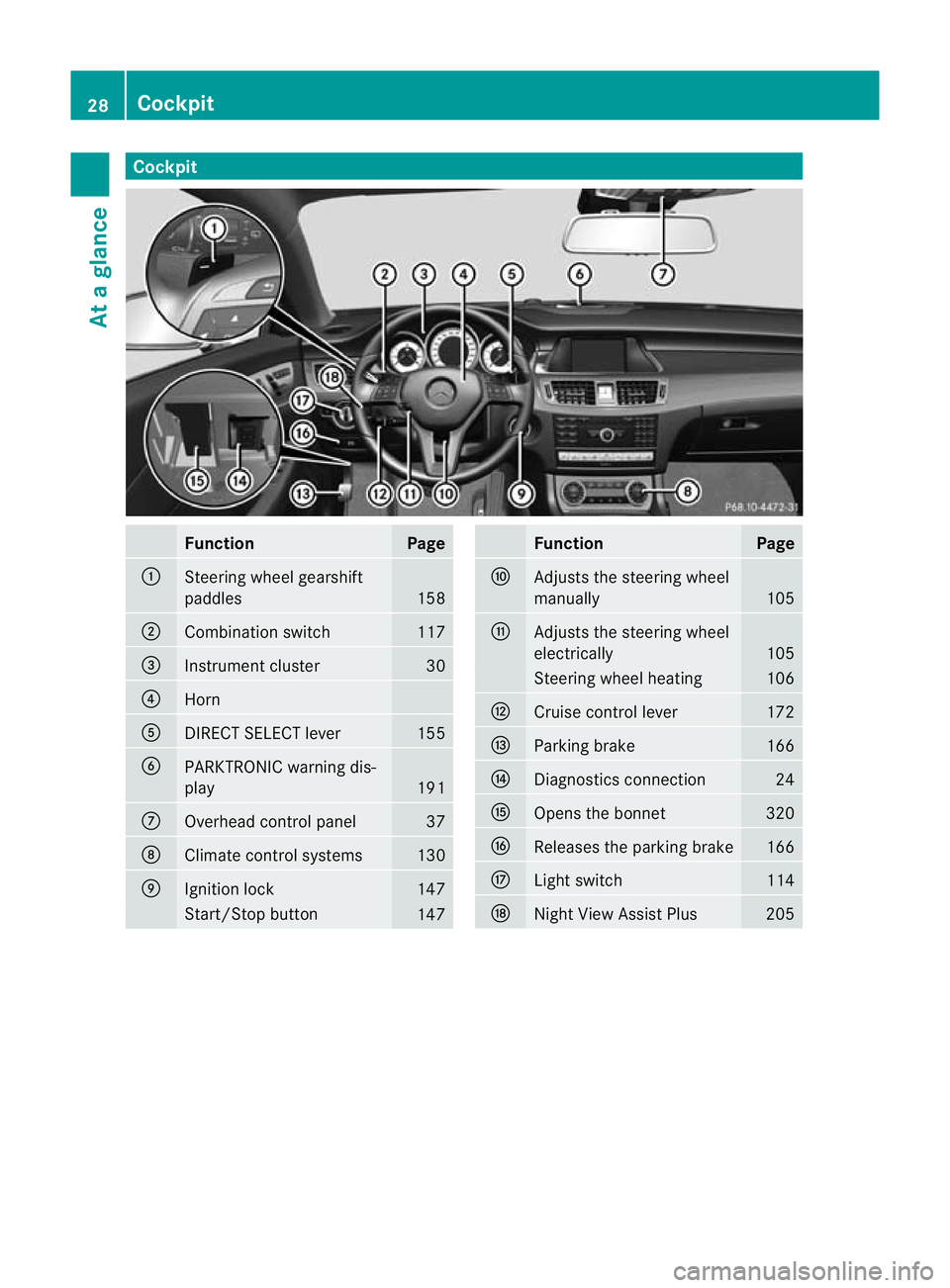
Cockpit
Function Page
:
Steering wheel gearshift
paddles
158
;
Combination switch 117
=
Instrument cluster 30
?
Horn
A
DIRECT SELECT lever 155
B
PARKTRONIC warning dis-
play
191
C
Overhead control panel 37
D
Climate control systems 130
E
Ignition lock 147
Start/Stop button
147 Function Page
F
Adjusts the steering wheel
manually 105
G
Adjusts the steering wheel
electrically 105
Steering wheel heating 106
H
Cruise control lever 172
I
Parking brake 166
J
Diagnostics connection 24
K
Opens the bonnet 320
L
Releases the parking brake 166
M
Ligh
tswitch 114
N
Night View Assist Plus 20528
CockpitAt a glance
Page 32 of 405
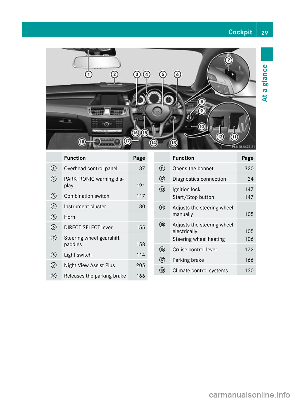
Function Page
:
Overhead control panel 37
;
PARKTRONIC warning dis-
play
191
=
Combination switch 117
?
Instrument cluster 30
A
Horn
B
DIRECT SELECT lever 155
C
Steering wheel gearshift
paddles
158
D
Ligh
tswitch 114
E
Nigh
tView Assist Plus 205
F
Releases the parking brake
166 Function Page
G
Opens the bonnet 320
H
Diagnostics connection 24
I
Ignition lock 147
Start/Stop button 147
J
Adjusts the steering wheel
manually
105
K
Adjusts the steering wheel
electrically
105
Steering wheel heating 106
L
Cruise control lever 172
M
Parking brake 166
N
Climate control systems 130Cockpit
29At a glance
Page 54 of 405
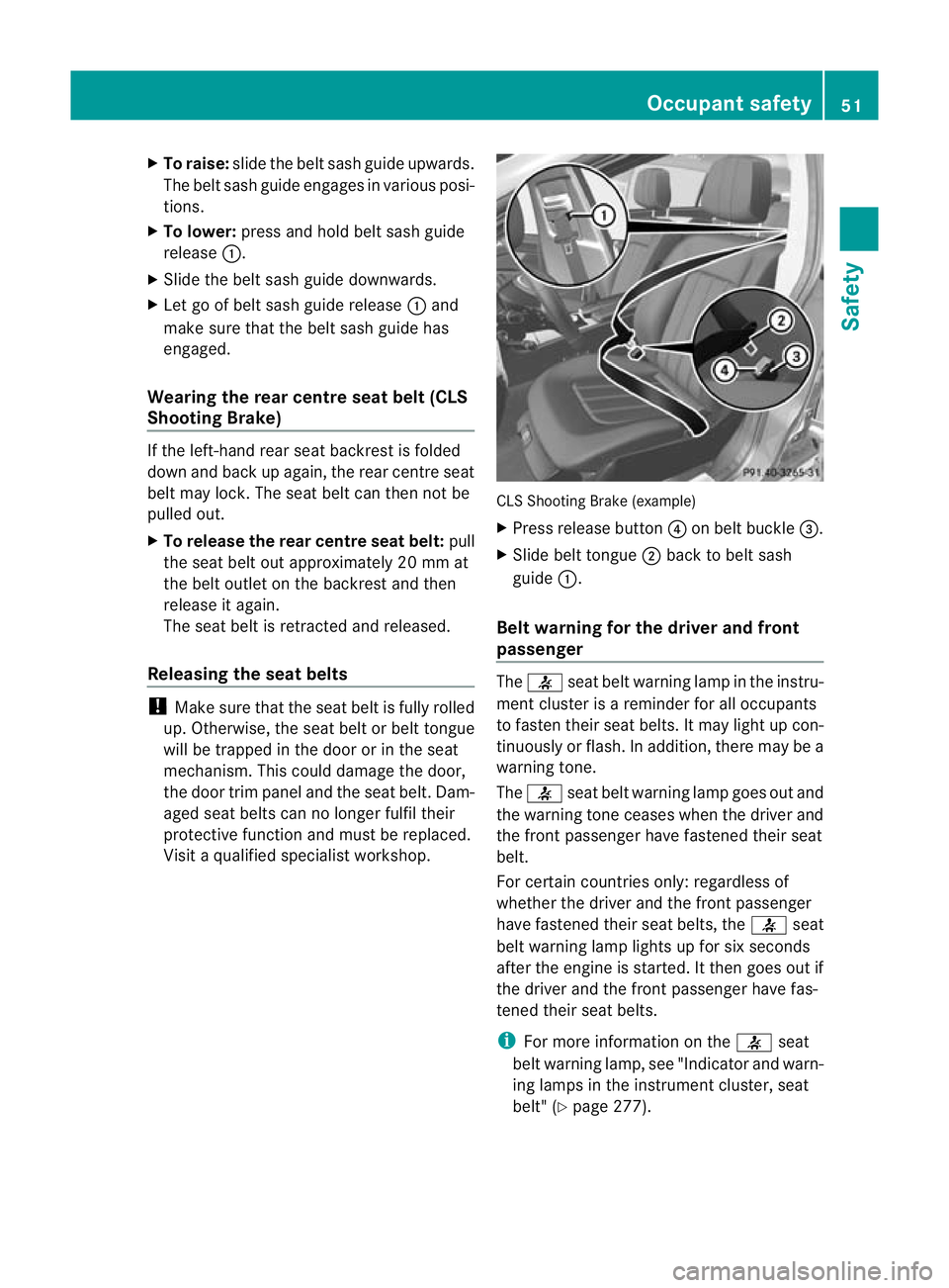
X
To raise: slide the belt sash guide upwards.
The belt sash guide engages in various posi-
tions.
X To lower: press and hold belt sash guide
release :.
X Slide the belt sash guide downwards.
X Let go of belt sash guide release :and
make sure tha tthe belt sash guide has
engaged.
Wearing the rear centre seat belt (CLS
Shooting Brake) If the left-hand rear seat backrest is folded
down and back up again, the rear centre seat
belt may lock. The seat belt can then not be
pulled out.
X To release the rear centre seat belt: pull
the seat belt out approximately 20 mm at
the belt outlet on the backrest and then
release it again.
The seat belt is retracted and released.
Releasing the seat belts !
Make sure that the seat belt is fully rolled
up. Otherwise, the seat belt or belt tongue
will be trapped in the door or in the seat
mechanism. This could damage the door,
the door trim panel and the seat belt. Dam-
aged seat belts can no longer fulfil their
protective function and must be replaced.
Visit a qualified specialist workshop. CLS Shooting Brake (example)
X
Press release button ?on belt buckle =.
X Slide belt tongue ;back to belt sash
guide :.
Belt warning for the driver and front
passenger The
7 seat belt warning lamp in the instru-
ment cluster is a reminder for all occupants
to fasten their seat belts. It may light up con-
tinuously or flash. In addition, there may be a
warning tone.
The 7 seat belt warning lamp goes out and
the warning tone ceases when the driver and
the front passenger have fastened their seat
belt.
For certain countries only: regardless of
whether the driver and the front passenger
have fastened their seat belts, the 7seat
belt warning lamp lights up for six seconds
after the engine is started. It then goes out if
the driver and the front passenger have fas-
tened their seat belts.
i For more information on the 7seat
belt warning lamp, see "Indicator and warn-
ing lamps in the instrumentc luster, seat
belt" (Y page 277). Occupant safety
51Safety Z
Page 124 of 405
tance to the other vehicle. Once the system
no longe rdetects any other vehicles, it reac-
tivates the main-beam headlamps.
The system's optical sensor is located behind
the windscreen near the overhead control
panel.
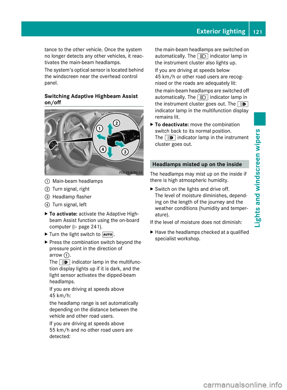
Switching Adaptive Highbeam Assist
on/off :
Main-beam headlamps
; Turn signal, right
= Headlamp flasher
? Turn signal, left
X To activate: activate the Adaptive High-
beam Assist function using the on-board
computer (Y page 241).
X Turn the light switch to Ã.
X Press the combination switch beyond the
pressure point in the direction of
arrow :.
The _ indicator lamp in the multifunc-
tion display lights up if it is dark, and the
light sensor activates the dipped-beam
headlamps.
If you are driving at speeds above
45 km/h:
the headlamp range is set automatically
depending on the distance between the
vehicle and other road users.
If you are driving at speeds above
55 km/h and no other road users are
detected: the main-beam headlamps are switched on
automatically. The
Kindicator lamp in
the instrument cluster also lights up.
If you are driving at speeds below
45 km/h or other road users are recog-
nised or the roads are adequately lit:
the main-beam headlamps are switched off
automatically. The Kindicator lamp in
the instrument cluster goes out. The _
indicator lamp in the multifunction display
remains lit.
X To deactivate: move the combination
switch back to its normal position.
The _ indicator lamp in the instrument
cluster goes out. Headlamps misted up on the inside
The headlamps may mist up on the inside if
there is high atmospheric humidity.
X Switch on the lights and drive off.
The level of moisture diminishes, depend-
ing on the length of the journey and the
weather conditions (humidity and temper-
ature).
If the level of moisture does not diminish:
X Have the headlamps checked at a qualified
specialist workshop. Exterior lighting
121Lights and windscreen wipers Z
Page 231 of 405
?
Coolan ttemperature (Y page 228)
A Fuel gauge Coolant temperature gauge
The coolant temperature gauge is in the
instrument cluster on the left-hand side
(Y page 30).
Under normal operating conditions and with
the specified coolant level, the coolant tem-
perature may rise to 120 †.
At high outside temperatures and when driv-
ing uphill, the coolant temperature may rise
to the end of the scale. Rev counter
! Do not drive in the overrevving range.
Doing so will damage the engine.
The red band in the rev counter indicates the
engine's overrevving range.
The fuel supply is interrupted to protec tthe
engine when the red band is reached. Outside temperature display
G
WARNING
At temperatures just above freezing point, the
street may be icy, especially in wooded areas
or on bridges. If you do not adapt your driving
style to the conditions, the vehicle could skid.
For this reason, adapt your driving style and
speed to the weather conditions.
The outside temperature displayi s in the mul-
tifunction display (Y page 229).
Changes in the outside temperature are dis-
played after a short delay. Speedometer with segments
The segments in the speedometer indicate
which speed range is available.
R Cruise control activated (Y page 171):The segments light up from the stored
speed to the maximum speed.
R Variable SPEEDTRONIC activated
(Y page 174):
The segments light up from the start of the
scale to the selected limit speed.
R DISTRONIC PLUS activated (Y page 177):
One or two segments in the set speed
range light up.
R DISTRONIC PLUS detects avehicle in front:
The segments between the speed of the
vehicle in fron tand the stored speed light
up. Operating the on-board computer
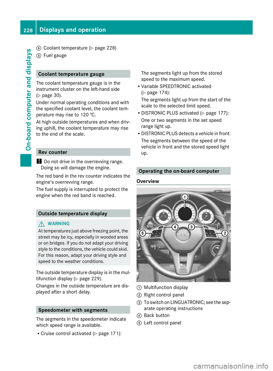
Overview :
Multifunctio ndisplay
; Right control panel
= To switch on LINGUATRONIC; see the sep-
arate operating instructions
? Back button
A Left control panel 228
Displays and operationOn-board computer and displays
Page 323 of 405
Useful information
i This Owner's Manual describes all mod-
els, series and optional equipment for your
vehicle that were available at the time of
going to press. National variations are pos-
sible. Note that your vehicle may not be
equipped with all of the functions descri-
bed. This is also the case for systems and
functions relevant to safety.
i Read the information on qualified special-
ist workshops: (Y page 24). Engine compartment
Bonnet
Opening the bonnet G
WARNING
Do not pull the release lever while the vehicle
is in motion. If you do so, the bonnet may open
up and block your view. G
WARNING
There is a risk of injury if the bonnet is open,
even if the engine is not running.
Some engine components can become very
hot.
To avoid the risk of burns, only touch those
components described in the Owner's Manual
and observe the relevan tsafety notes. G
WARNING
The radiator fan between the radiator and the
engine can start automatically, even if the key
has been removed from th eignition lock. For
this reason, you must not reach into the fan
rotation area. You could otherwise be injured. Vehicles with
apetrol engine: The elec-
tronic ignitio nsystem uses high voltage. For
this reason, you mus tnever touch ignition
system components (ignition coil, ignition
cables, spark plug connectors or test socket)
while:
R the engine is running
R the engine is being started
R the ignition is switched on and the engine
is being cranked by hand
You could otherwise suffer an electric shock
and be seriously or even fatally injured.
Vehicles with adiesel engine: The elec-
tronic injection control uses high voltage. For
this reason, you must never touch injection
system components while:
R the engine is running
R the engine is being started
R the ignition is switched on
You could otherwise suffer an electric shock
and be seriously or even fatally injured. G
WARNING
The windscreen wipers and wiper linkage
could be set in motion.
When the bonnet is open, you or others could
be injured by the wiper linkage.
Make sure that the windscreen wipers are
switched off. Remove the key or make sure
that no ignition position has been selected
with KEYLESS-GO. All indicator lamps must be
off in the instrument panel.
! Make sure that the windscreen wipers are
not folded away from the windscreen .Oth-
erwise, you could damage the windscreen
wipers or the bonnet. 320
Engine compartmentMaintenance and care