radio MERCEDES-BENZ CLS SHOOTING BRAKE 2012 Owners Manual
[x] Cancel search | Manufacturer: MERCEDES-BENZ, Model Year: 2012, Model line: CLS SHOOTING BRAKE, Model: MERCEDES-BENZ CLS SHOOTING BRAKE 2012Pages: 405, PDF Size: 10.21 MB
Page 14 of 405
Folding in whe
nlocking (on-board
computer) ...................................... 245
Out of position (troubleshooting) ...109
Parking position ............................. 110
Resetting ....................................... 109
Storing settings (memory func-
tion) ............................................... 111F
Faul tmessage
see Display messages
Filler cap
see Fuel filler flap
Fire extinguisher ............................... 335
First-aid kit ......................................... 334
Fitting awheel
Removing awheel .......................... 365
Fitting wheels
Fitting awheel ............................... 366
Lowering the vehicle ......................366
Raising the vehicle .........................364
Securing the vehicle against roll-
ing away ........................................ 363
Flat tyre
MOExtended tyres .........................337
Preparing the vehicle .....................336
TIREFIT kit ...................................... 338
Floormat ............................................ .317
Foglamps (extende drange) .............. 120
Frequencies Garage door opener .......................314
Mobile phone ................................. 383
Two-way radio ................................ 383
Front foglamps
Display message ............................ 257
Fuel
Additives ........................................ 389
Consumption information ..............390
Consumption statistics ..................231
Displaying the current consump-
tion ................................................ 231
Displaying the range ......................231
Fuel gauge ............................... 30, 227
Grade (petrol) ................................ 387
Important safety notes ..................386
Notes for AMG vehicles .................388
Problem (malfunction) ...................164Quality (diesel
)............................... 389
Refuelling ...................................... .161
Tank content/reserve fuel .............387
Fuel filler flap
Emergency release ........................163
Opening/closing ............................ 162
Fuel filte r(white display message) .261
Fuel level Calling up the range (on-board
computer) ...................................... 231
Gauge ...................................... 30, 227
Fuel reserve
see Fuel
Fuel tank
Capacity ........................................ 387
Problem (malfunction) ...................164
Fuse allocation chart (vehicle tool
kit) ...................................................... 335
Fuses Allocation chart ............................. 350
Before changing ............................. 350
Fuse box in the boot ......................351
Fuse box in the engine compart-
ment .............................................. 350
Fuse box in the luggage compart-
ment .............................................. 351
Important safety notes ..................350 G
Garage door opener Clearing the memory .....................313
Frequencies ................................... 314
Important safety notes ..................311
Opening/closing the garage door ..313
Programming (button in the rear-
view mirror) ................................... 312
Gear indicator (on-board com-
puter) ................................................. .246
Gearshift program SETUP (on-board computer) ..........246
Genuine Mercedes-Benz parts .........382
Glove compartment ..........................291 Index
11
Page 18 of 405
Instrument cluster submenu
..........239
Ligh tsubmenu ............................... 240
Menu overview .............................. 230
Message memory .......................... 249
Navigation menu ............................ 232
Operating the TV ............................ 234
Operating vide oDVD ..................... 234
Operation ....................................... 228
RACETIMER ................................... 246
Service menu ................................. 239
Settings menu ............................... 239
Standard displa y............................ 230
Telephone menu ............................ 235
Trip menu ...................................... 230
Vehicle submenu ........................... 242
Operating system
see On-board computer
Outside temperature display ...........228
Overhead control panel ......................37
Override feature Rea rside windows ........................... 63 P
Pain tcode .......................................... 384
Paintwork (cleaning instructions) ...327
Panic alarm .......................................... 40
Parking ............................................... 165
Important safety notes ..................165
Parking brake ................................ 166
Position of exterior mirror, front-
passenger side ............................... 110
Reversing camera ..........................198
see PARKTRONIC
Parking aid
Active Parking Assist .....................194
see Exterior mirrors
see PARKTRONIC
Parking brake
Display message ............................ 252
Notes/function .............................. 166
Warning lamp ................................. 284
Parking lamps
Display message ............................ 257
Switching on/off ........................... 117
PARKTRONIC
Deactivating/activating .................193
Driving system ............................... 191Function/notes
............................. 191
Important safety notes ..................191
Problem (fault) ............................... 194
Sensor range ................................. 192
Trailer towing ................................. 193
Warning displa y............................. 193
PASSENGE RAIRBAG OFF warning
lamp ...................................................... 55
Petrol .................................................. 387
Plastic trim (cleaning instructions) .330
Power windows see Side windows
PRE-SAFE ®
(preventive occupant
safety system) Display message ............................ 253
Operation ........................................ .48
PRE-SAFE ®
Brake
Activating/deactivating .................237
Display message ............................ 253
Function/notes ................................ 70
Warning lamp ................................. 287
Product information ............................22
Program selector button ..................157
Protection of the environment General notes .................................. 22
Pulling away (automatic transmis-
sion) .................................................... 149 Q
Qualifie dspecialis tworkshop ...........24 R
RACE START (AMG vehicles) .............187
RACETIMER (on-board computer) ....246
Radar sensors Overview ........................................ 398
Radar sensor system
Activating/deactivating .................243
Display message ............................ 263
Radiator cover ................................... 321
Radio Selecting astation ......................... 233
see separate operating instructions
Rain closing feature (slidin gsun-
roof) ...................................................... 93
Reading lamp ..................................... 122 Index
15
Page 22 of 405
Temperature
Coolant .......................................... 228
Coolant (on-board computer) ......... 246
Engine oil (on-board computer) ...... 246
Outside temperature ..................... .228
Setting (climate control) ................134
TEMPOMAT
Function/notes ............................. 171
Theft-deterrent system
ATA (Anti-Theft Alarm system) .........72
Immobiliser ...................................... 72
Through-loading feature ...................293
Timing (RACETIMER) .........................246
Tiredness Assist see ATTENTION ASSIST
TIREFIT kit .......................................... 338
Top Tether ............................................ 57
Total distance recorder ....................230
Tow-away protection ..........................73
Towing Important safety notes ..................346
With the rear axle raised ................348
Towing atrailer
Activ eBlind Spot Assist .................215
Active Lane Keeping Assist ............217
Active Parking Assist .....................197
Axle load, permissible ....................398
Bulb failure indicator for LED
lamps ............................................. 223
ESP ®
(Electroni cStability Pro-
gram) ............................................... 69
Towing away
Fitting the towing eye. ...................347
Removing the towing eye. ..............348
With both axles on the ground .......348
Tow-starting
Emergency engine starting ............349
Important safety notes ..................346
Trailer
Display message ............................ 274
Trailer coupling
see Towing atrailer
Trailer towing
7-pin connector ............................. 223
Blind Spot Assist ............................ 210
Cleaning the trailer tow hitch ......... 329
Coupling up atrailer ...................... 221Decoupling
atrailer ....................... 221
Driving tips .................................... 219
Folding in the ball coupling ............221
Folding out the ball coupling ..........220
Important safety notes ..................217
Lights displa ymessage .................. 255
Mounting dimensions ....................396
Parktroni c...................................... 193
Power supply ................................. 222
Shift range ..................................... 157
Trailer loads ................................... 398
Transmission
see Automatic transmission
Transmission position display .........155
Transmission position display
(DIRECT SELECTl ever)...................... 155
Transporting the vehicle ..................349
Trim pieces (cleaning instructions) .331
Trip computer (on-board com-
puter) ................................................. .231
Trip meter Calling up ....................................... 230
Resetting (on-board computer) ......232
Turn signal
see Turn signals
Turn signals
Switching on/off ........................... 117
TV
Operating (on-board computer) .....234
see Separate operating instructions
Two-way radio
Frequencies ................................... 383
Installatio n..................................... 383
Transmission output (maximum) .... 383
Type identification plate
see Vehicle identification plate
Tyre pressure
Calling up (on-board computer) .....360
Display message ............................ 268
Not reached (TIREFIT) ....................339
Reached (TIREFIT) ..........................339
Recommended ............................... 357
Tyre pressure loss warning
Important safety notes ..................358
Restarting ...................................... 359 Index
19
Page 27 of 405
functions in systems which have not been
modified .Malfunctions such as these can
seriously jeopardise the vehicle's operating
safety and therefore your own safety.
You should therefore have all work and mod-
ifications to electronic components carried
out at a qualified specialist workshop. Declarations of conformity
Wireless vehicle components The following informatio
napplies to all com-
ponents of the vehicle and the COMAND sys-
tem which receive and/or transmit radio
waves:
The components of this vehicle which receive
and/or transmit radio waves are compliant
with the basic requirements and other rele-
vant provision sof Directive 1999/5/EC. You
can obtain further information from any
Mercedes-Benz Service Centre.
Electromagnetic compatibility The electromagnetic compatibility of the vehi-
cle components has been checked and certi-
fied according to the currently valid version
of Directive 72/245/EEC or the equivalent
ECE Regulation ECE-R 10. Diagnostics connection
G
WARNING
If you connect equipment to a diagnostics
connection, it can affect the operation of the
vehicle systems. This could compromise the
operating safety of you rvehicle while driving.
There is a risk of an accident.
Do not connect any equipment to a diagnos-
tics connection. G
WARNING
Loose equipment or cables hanging from a
device which are connected to a diagnostic
connection could impede pedal clearance. The equipment or cables could get caught
between the pedals when driving and braking
suddenly. This could impair the function of the
pedals. There is a risk of accident.
Do not attach any equipment or cables in the
driver's footwell.
! If the engine is switched off and equip-
ment on the diagnostics connection is
used, the starter batter ymay discharge.
The diagnostics connection is only intended
for the connection of diagnostic equipmen tat
a qualified specialist workshop.
Connecting equipmen tto the diagnostics
connection can lead to emissions monitoring
information being reset, for example. This
may lead to the vehicle failing to meet the
requirements of the next emissions test dur-
ing the main inspection. Qualified specialist workshop
Aq ualified specialist workshop has the nec-
essary special skills, tools and qualifications
to correctly carry out any necessary work on
your vehicle. This particularly applies to work
relevan tto safety.
Observe the notes in the Service Booklet.
Always have the following work carried out at
a qualified specialist workshop:
R work relevant to safety
R service and maintenance work
R repair work
R modifications, installations and conver-
sions
R work on electronic components
Mercedes-Benz recommends that you use a
Mercedes-Benz Service Centre. Vehicle registration
Mercedes-Benz may ask its Service Centres
to carry out technical inspections on certain 24
Introduction
Page 68 of 405
G
WARNING
If BAS is malfunctioning, the braking distance
in an emergency braking situation is
increased. There is a risk of accident.
In an emergency braking situation, depress
the brake pedal with full force. ABS prevents
the wheels from locking.
BAS operates in emergency braking situa-
tions. If you depress the brake pedal quickly,
BAS automatically boosts the braking force,
thus shortening the stopping distance.
The brakes will function as usual once you
release the brake pedal. BAS is deactivated. BAS PLUS (Brake Assist System Plus)
i Observe the "Important safety notes" sec-
tion (Y page 64).
BAS PLUS is only available on vehicles with
DISTRONIC PLUS.
BAS PLUS provides braking assistance in haz-
ardous situations at speeds greater than
7k m/h and uses rada rsensor technology to
assess the traffic situation.
With the help of the radar sensor system, BAS
PLUS can detect obstacles that are in the
path of your vehicle for an extended period of
time.
At speeds up to approximately 70 km/h, BAS
PLUS may also detect stationary obstacles,
for example, stopped or parked vehicles.
To prevent a front-end collision, BAS PLUS
calculates the brake force necessary if:
R you approach an obstacle and
R BAS PLUS has detected a risk of collision.
When driving at a speed over 30 km/h : if
you depress the brake pedal sharply, BAS
PLUS will automatically increase the braking
force to a level suitable for the traffic condi-
tions.
When driving at a speed under 30 km/h :
if you depress the brake, BAS PLUS is activa-
ted. Braking will be carried ou tatthe last
possible moment. If BAS PLUS demands particularly high brak-
ing force, preventative passenger protection
measures (PRE-SAFE
®
) are activated simul-
taneously.
X Keep the brake pedal depressed until the
emergency braking situation is over.
ABS prevents the wheels from locking.
BAS PLUS is deactivated and the brakes func-
tion as usual, if:
R you release the brake pedal
R there is no longer any danger of a rear-end
collision
R no obstacle is detected in front of your
vehicle.
The radar sensor system is switched off auto-
matically in the vicinity of radio telescope
facilities in the following vehicles:
R vehicles with COMAND Online and naviga-
tion
R vehicles with Audio 20 and Becker ®
MAP
PILOT
Becker ®
MAP PILOT must be connected,
see the separate operating instructions
The radar sensor system must be switched off
using the on-board computer in the vicinity of
radio telescope facilities in the following vehi-
cles:
R vehicles without COMAND Online and nav-
igation
R vehicles without Audio 20 and Becker ®
MAP PILOT
R vehicles for Australia
For information on switching off the radar
sensor system using the on-board computer,
see (Y page 243).
For BAS PLUS to assist you when driving, the
radar sensor system must:
R be switched on (Y page 243)
R be operational (Y page 263)
If the radar sensor system is malfunctioning,
BAS PLUS will not be available. The brake
system is still available with complete brake
boosting effect and BAS. Driving safety systems
65Safety Z
Page 74 of 405
If you approach an obstacle and PRE-SAFE
®
Brake detects a risk of a collision, the system
will alert you both visually and acoustically. If
you do not brake or take evasive action, the
system will warn you by automatically braking
the vehicle gently. If there is an increased risk
of collision, preventative passenger protec-
tion measures (PRE-SAFE ®
) are activated
(Y page 48). If, at speeds over 30 km/h, a risk
of collision remains and you do not brake,
take evasive action or significantly acceler-
ate, automatic braking may be performed up
to a level of automatic emergency braking.
Automatic emergency braking is not per-
formed until immediately prior to an accident
that can no longer be avoided. G
WARNING
PRE-SAFE ®
Brake will initially brake yourv ehi-
cle by a partial application of the brakes if a
danger of collision is detected. There may be
a collision unless you also brake. Automatic
emergency braking cannot prevent a colli-
sion. There is a risk of an accident.
Always apply the brakes yourself and try to
take evasive action. G
WARNING
PRE-SAFE ®
Brake cannot always clearly iden-
tify objects and complex traffic conditions.
In these cases, PRE-SAFE ®
Brake may:
R give an unnecessary warning and then
brake the vehicle
R neither give a warning nor intervene
There is a risk of an accident.
Always pay particular attention to the traffic
situation and be ready to brake, especially if
PRE-SAFE ®
Brake warns you. Terminate the
intervention in a non-critical driving situation.
In particular, the detection of obstacles can
be impaired if there is:
R dirt on the sensors or anything else cover-
ing the sensors
R snow or heavy rain
R interference by other radar sources R
the possibility of strong radar reflections,
for example, in multi-storey car parks
R a narrow vehicle travelling in front, e.g. a
motorcycle
R a vehicle travelling in front on a different
line G
WARNING
PRE-SAFE ®
Brake does not react:
R to people or animals
R to oncoming vehicles
R to crossing traffic
R when cornering
As a result, PRE-SAFE ®
Brake may neither
give warnings nor intervene in all critical sit-
uations. There is a risk of an accident.
Always pay careful attention to the traffic sit-
uation and be ready to brake.
In order to maintain the appropriate distance
to the vehicle in fron tand thus prevent a col-
lision, you must apply the brakes yourself.
X To activate/deactivate: activate or deac-
tivate PRE-SAFE ®
Brake in the on-board
computer (Y page 237).
When PRE-SAFE ®
Brake is activated, the
Ä symbol appears in multifunctio ndis-
play, as long as the HOL Dfunction is deac-
tivated (Y page 186). On vehicles with the
Active Parking Assist driving system, the
Ä symbol is displayed when position P
is engaged or you are driving faste rthan
35 km/h.
For PRE-SAFE ®
Brake to assist you when driv-
ing, the radar sensor system must be
switched on (Y page 243) and be opera-
tional.
The radar sensor system is switched off auto-
matically in the vicinity of radio telescope
facilities in the following vehicles:
R vehicles with COMAND Online and naviga-
tion
R vehicles with Audio 20 and Becker ®
MAP
PILOT Driving safety systems
71Safety Z
Page 75 of 405
Becker
®
MAP PILOT must be connected;
see the separate operating instructions.
The radar senso rsystem mus tbe switched off
using the on-board computer in the vicinity of
radio telescope facilities in the following vehi-
cles:
R vehicles without COMAND Online and nav-
igation
R vehicles without Audio 20 and Becker ®
MAP PILOT
R vehicles for Australia
For information on switching off the radar
sensor system using the on-board computer,
see (Y page 243).
Following damage to the fron tend of the vehi-
cle, have the configuratio nand operatio nof
the rada rsensors checked at a qualified spe-
cialist workshop. This also applies to colli-
sions at slow speeds where there is no visible
damage to the fron tofthe vehicle. Anti-theft systems
Immobiliser
The immobiliser prevents your vehicle from
being started without the correct key.
X To activate with the key: remove the key
from the ignition lock.
X To activate with KEYLESS-GO: switch the
ignition off and open the driver's door.
X To deactivate: switch on the ignition.
When leaving the vehicle, always take the key
with you and lock the vehicle. Anyone can
start the engine if a valid key has been left
inside the vehicle.
i The immobiliser is always deactivated
when you start the engine. ATA (Anti-Theft Alarm system)
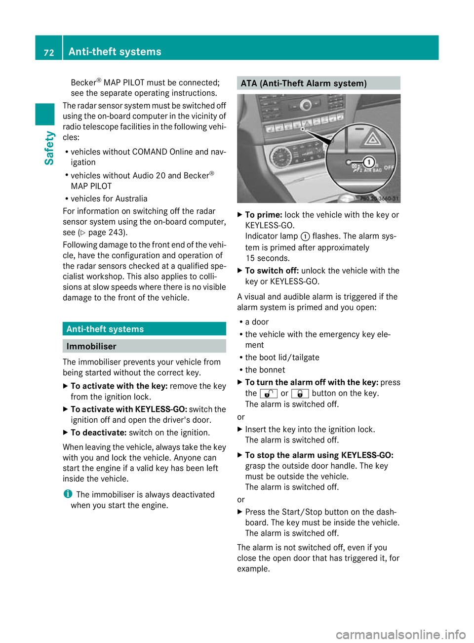
X
To prime: lock the vehicle with the key or
KEYLESS-GO.
Indicator lamp :flashes. The alarm sys-
tem is primed after approximately
15 seconds.
X To switch off: unlock the vehicle with the
key or KEYLESS-GO.
Av isual and audible alarm is triggered if the
alarm system is primed and you open:
R a door
R the vehicle with the emergency key ele-
ment
R the boot lid/tailgate
R the bonnet
X To turn th ealarm off with th ekey: press
the % or& button on the key.
The alarm is switched off.
or
X Insert the key into the ignition lock.
The alarm is switched off.
X To stop the alarm using KEYLESS-GO:
grasp the outside door handle. The key
must be outside the vehicle.
The alarm is switched off.
or
X Press the Start/Stop button on the dash-
board. The key must be inside the vehicle.
The alarm is switched off.
The alarm is not switched off, even if you
close the open door that has triggered it, for
example. 72
Anti-theft systemsSafety
Page 80 of 405
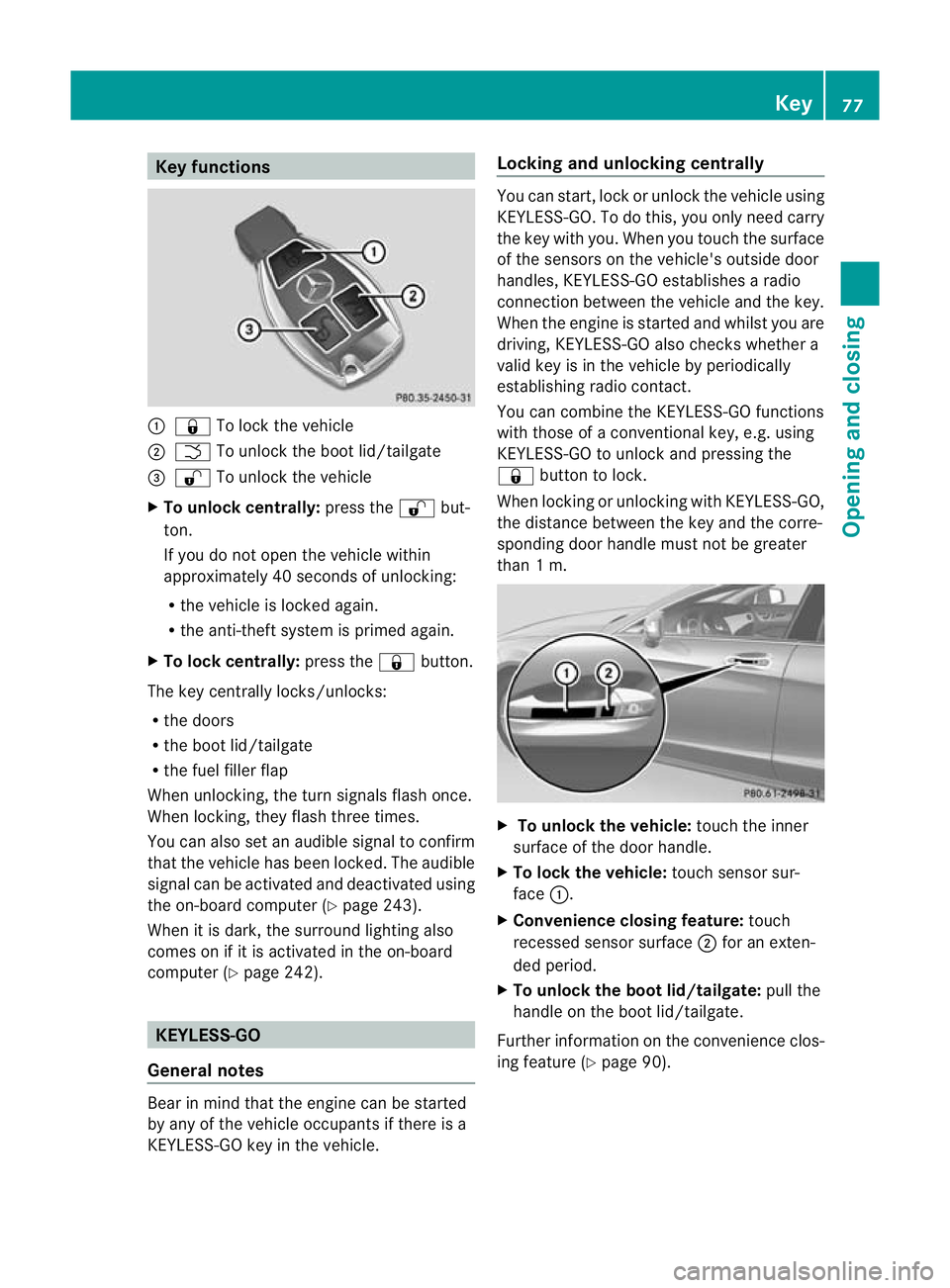
Key functions
:
& To loc kthe vehicle
; F To unlock the boot lid/tailgate
= % To unlock the vehicle
X To unlock centrally: press the%but-
ton.
If you do not open the vehicle within
approximately 40 seconds of unlocking:
R the vehicle is locked again.
R the anti-theft system is primed again.
X To lock centrally: press the&button.
The key centrally locks/unlocks:
R the doors
R the boot lid/tailgate
R the fuel filler flap
When unlocking, the turn signals flash once.
When locking, they flash three times.
You can also set an audible signal to confirm
that the vehicle has been locked. The audible
signal can be activated and deactivated using
the on-board computer (Y page 243).
When it is dark, the surround lighting also
comes on if it is activated in the on-board
computer (Y page 242). KEYLESS-GO
General notes Bear in mind that the engine can be started
by any of the vehicle occupants if there is a
KEYLESS-GO key in the vehicle. Locking and unlocking centrally You can start, lock or unlock the vehicle using
KEYLESS-GO. To do this, you only need carry
the key with you. When you touch the surface
of the sensors on the vehicle's outside door
handles, KEYLESS-GO establishes a radio
connection between the vehicle and the key.
When the engine is started and whilst you are
driving, KEYLESS-GO also checks whether a
valid key is in the vehicle by periodically
establishing radio contact.
You can combine the KEYLESS-GO functions
with those of a conventional key, e.g. using
KEYLESS-GO to unlock and pressing the
&
button to lock.
When locking or unlocking with KEYLESS-GO,
the distance between the key and the corre-
sponding door handle must not be greater
than 1 m. X
To unlock the vehicle: touch the inner
surface of the door handle.
X To lock the vehicle: touch sensor sur-
face :.
X Convenience closing feature: touch
recessed sensor surface ;for an exten-
ded period.
X To unlock the boot lid/tailgate: pull the
handle on the boot lid/tailgate.
Further information on the convenience clos-
ing feature (Y page 90). Key
77Opening and closing Z
Page 84 of 405
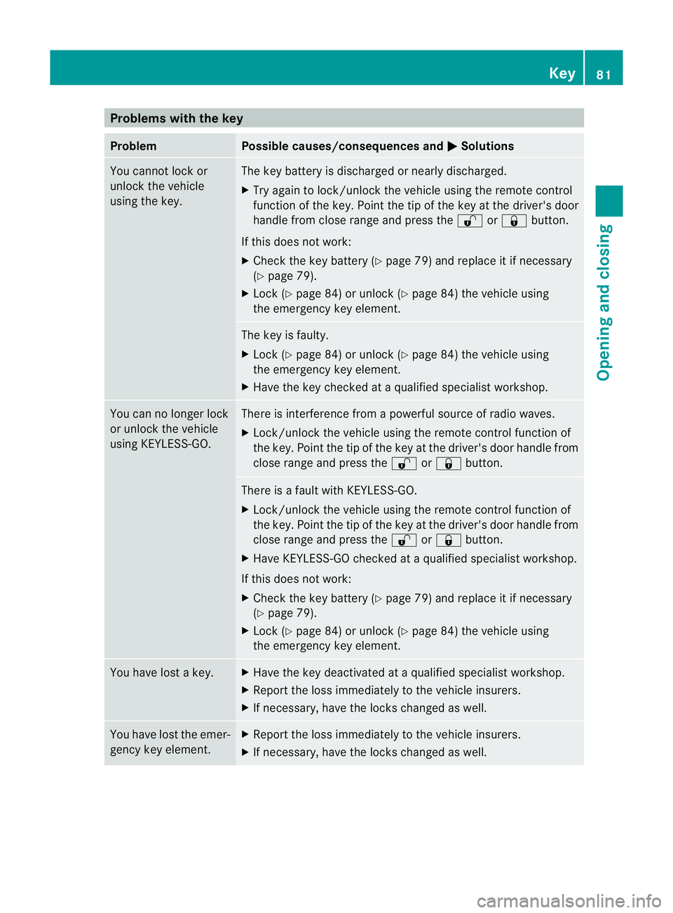
Problems with the key
Problem Possible causes/consequences and
M Solutions
You cannot lock or
unlock the vehicle
using the key. The key battery is discharged or nearly discharged.
X
Try again to lock/unlock the vehicle using the remote control
function of the key. Point the tip of the key at the driver's door
handle from close range and press the %or& button.
If this does not work:
X Check the key battery (Y page 79) and replace it if necessary
(Y page 79).
X Lock (Y page 84) or unlock (Y page 84) the vehicle using
the emergency key element. The key is faulty.
X
Lock (Y page 84) or unlock (Y page 84) the vehicle using
the emergency key element.
X Have the key checked at a qualified specialist workshop. You can no longer lock
or unlock the vehicle
using KEYLESS-GO. There is interference from a powerful source of radio waves.
X Lock/unlock the vehicle using the remote control function of
the key. Point the tip of the key at the driver's door handle from
close range and press the %or& button. There is a fault with KEYLESS-GO.
X
Lock/unlock the vehicle using the remote control function of
the key. Point the tip of the key at the driver's door handle from
close range and press the %or& button.
X Have KEYLESS-GO checked at a qualified specialist workshop.
If this does not work:
X Check the key battery (Y page 79) and replace it if necessary
(Y page 79).
X Lock (Y page 84) or unlock (Y page 84) the vehicle using
the emergency key element. You have lost a key. X
Have the key deactivated at a qualified specialist workshop.
X Report the loss immediately to the vehicle insurers.
X If necessary, have the locks changed as well. You have lost the emer-
gency key element. X
Report the loss immediately to the vehicle insurers.
X If necessary, have the locks changed as well. Key
81Opening and closing Z
Page 85 of 405
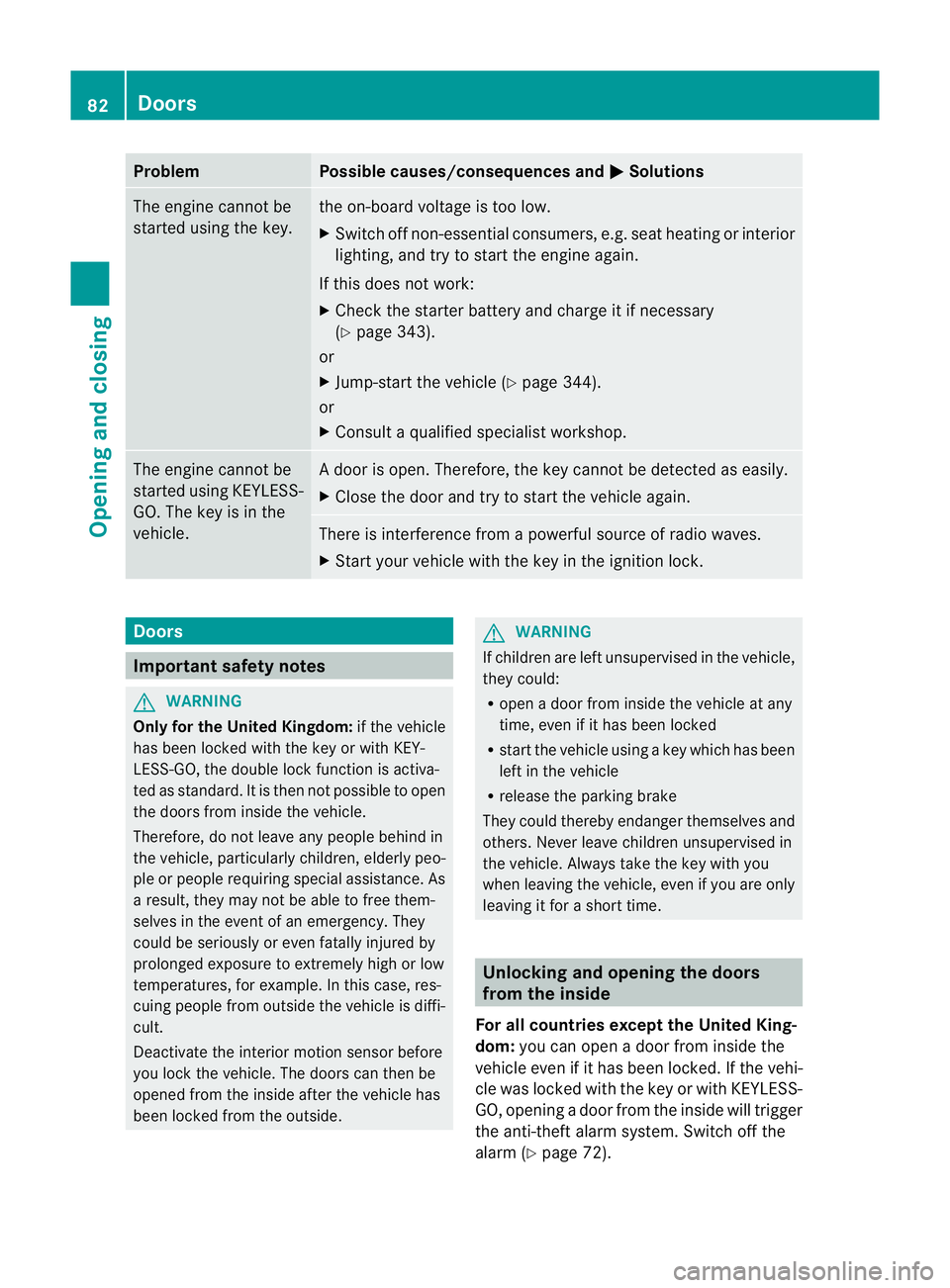
Problem Possible causes/consequences and
M Solutions
The engine cannot be
started using the key. the on-board voltage is too low.
X
Switch off non-essential consumers, e.g. seat heating or interior
lighting, and try to start the engine again.
If this does not work:
X Check the starter battery and charge it if necessary
(Y page 343).
or
X Jump-start the vehicle (Y page 344).
or
X Consult a qualified specialist workshop. The engine cannot be
started using KEYLESS-
GO. The key is in the
vehicle. Ad
oor is open. Therefore, the key cannot be detected as easily.
X Close the door and try to start the vehicle again. There is interference from a powerful source of radio waves.
X
Start your vehicle with the key in the ignition lock. Doors
Important safety notes
G
WARNING
Only for the United Kingdom: if the vehicle
has been locked with the key or with KEY-
LESS-GO, the double lock function is activa-
ted as standard. It is then not possible to open
the doors from inside the vehicle.
Therefore, do not leave any people behind in
the vehicle, particularly children, elderly peo-
ple or people requiring special assistance. As
a result, they may not be able to free them-
selves in the event of an emergency. They
could be seriously or even fatally injured by
prolonged exposure to extremely high or low
temperatures, for example. In this case, res-
cuing people from outside the vehicle is diffi-
cult.
Deactivate the interior motion sensor before
you lock the vehicle. The doors can then be
opened from the inside after the vehicle has
been locked from the outside. G
WARNING
If children are left unsupervised in the vehicle,
they could:
R open a door from inside the vehicle at any
time, even if it has been locked
R start the vehicle using akey which has been
left in the vehicle
R release the parking brake
They could thereby endanger themselves and
others. Never leave children unsupervised in
the vehicle. Always take the key with you
when leaving the vehicle, even if you are only
leaving it for a short time. Unlocking and opening the doors
from the inside
For all countries except the United King-
dom: you can open a door from inside the
vehicle even if it has been locked. If the vehi-
cle was locked with the key or with KEYLESS-
GO, opening a door from the inside will trigger
the anti-theft alarm system. Switch off the
alarm (Y page 72). 82
DoorsOpening and closing