stop start MERCEDES-BENZ E-Class CABRIOLET 2014 C207 Repair Manual
[x] Cancel search | Manufacturer: MERCEDES-BENZ, Model Year: 2014, Model line: E-Class CABRIOLET, Model: MERCEDES-BENZ E-Class CABRIOLET 2014 C207Pages: 394, PDF Size: 5.28 MB
Page 339 of 394

It is better to have the vehicle transported
than to have it towed.
If the vehicle has suffered transmission
damage, have it transported on a transporter
or trailer.
The automatic transmission must be in
position Nwhen the vehicle is being towed.
The battery must be connected and charged.
Otherwise, you:
R cannot turn the SmartKey to position 2in
the ignition lock
R cannot shift the automatic transmission to
position N
i Disarm the automatic locking feature
before the vehicle is towed (Y page 89). You
could otherwise be locked out when
pushing or towing the vehicle. Installing/removing the towing eye
Installing the towing eye G
WARNING
The exhaust tail pipe may be very hot. There
is a risk of burns when removing the rear
cover.
Do not touch the exhaust pipe.T ake particular
care when removing the rear cover. Towing eye covers (example
:Coupe)
The mountings for the removable towing eyes
are located in the bumpers. They are at the
front and at the rear, behind the covers.
X Remove the towing eye from the vehicle
tool kit (Y page 328).
X Press the mark on cover 0002inwards in the
direction of the arrow.
X Take cover 0002off the opening.
X Screw in and tighten the towing eye
clockwise to the stop.
Removing the towing eye X
Unscrew and remove the towing eye.
X Attach cover 0002to the bumper and press
until it engages.
X Place the towing eye in the vehicle tool kit. Towing the vehicle with the rear axle
raised
! The ignition must be switched off if you
are towing the vehicle with the rear axle
raised. Intervention by ESP ®
could
otherwise damage the brake system. Towing and tow-starting
337Breakdown assistance Z
Page 341 of 394

You can find information on "Jump-starting"
under (Y page 334). Fuses
Important safety notes
G
WARNING
If you manipulate or bridge a faulty fuse or if
you replace it with a fuse with a higher
amperage, the electric cables could be
overloaded. This could result in a fire. There
is a risk of an accident and injury.
Always replace faulty fuses with the specified
new fuses having the correc tamperage.
! Only use fuses that have been approved
for Mercedes-Benz vehicles and which
have the correct fuse rating for the system
concerned. Otherwise, components or
systems could be damaged.
The fuses in yourv ehicle serve to close down
faulty circuits. If afuse blows, all the
components on the circuit and their functions
stop operating.
Blown fuses must be replace dwith fuses of
the same rating, which you can recognize by
the color and value. The fuse ratings are listed
in the fuse allocation chart.
If a newly inserted fuse also blows, have the
cause traced and rectified at a qualified
specialist workshop, e.g. an authorized
Mercedes-Ben zCenter. Before changing a fuse
Observe the important safety notes
(Y page 339)
X Secure the vehicle against rolling away
(Y page 182).
X Switch off all electrical consumers. X
Turn the SmartKey to position 0in the
ignition lock and remove it (Y page 165).
or
X On vehicles with KEYLESS-GO, make sure
the ignition is switched off (Y page 165).
All indicator lamps in the instrument cluster
must be off.
The fuses are located in various fuse boxes:
R Fuse box on the driver's side of the
dashboard
R Fuse box in the engine compartment on the
left-hand side of the vehicle, when viewed
in the direction of travel
R Fuse box in the trun konthe right-hand side
of the vehicle, when viewed in the direction
of travel
The fuse allocation chart is located in the
vehicle tool kit in the stowage compartment
under the trunk floor (Y page 328). Dashboard fuse box
Observe the important safety notes
(Y page 339)
! Do not use a pointed object such as a
screwdriver to open the cover in the
dashboard. You could damage the
dashboard or the cover.
! Make sure that no moisture can enter the
fuse box when the cover is open.
! When closing the cover, make sure that it
is lying correctly on the fuse box. Moisture
seeping in or dirt could otherwise impair
the operation of the fuses. Fuses
339Breakdown assistance Z
Page 355 of 394

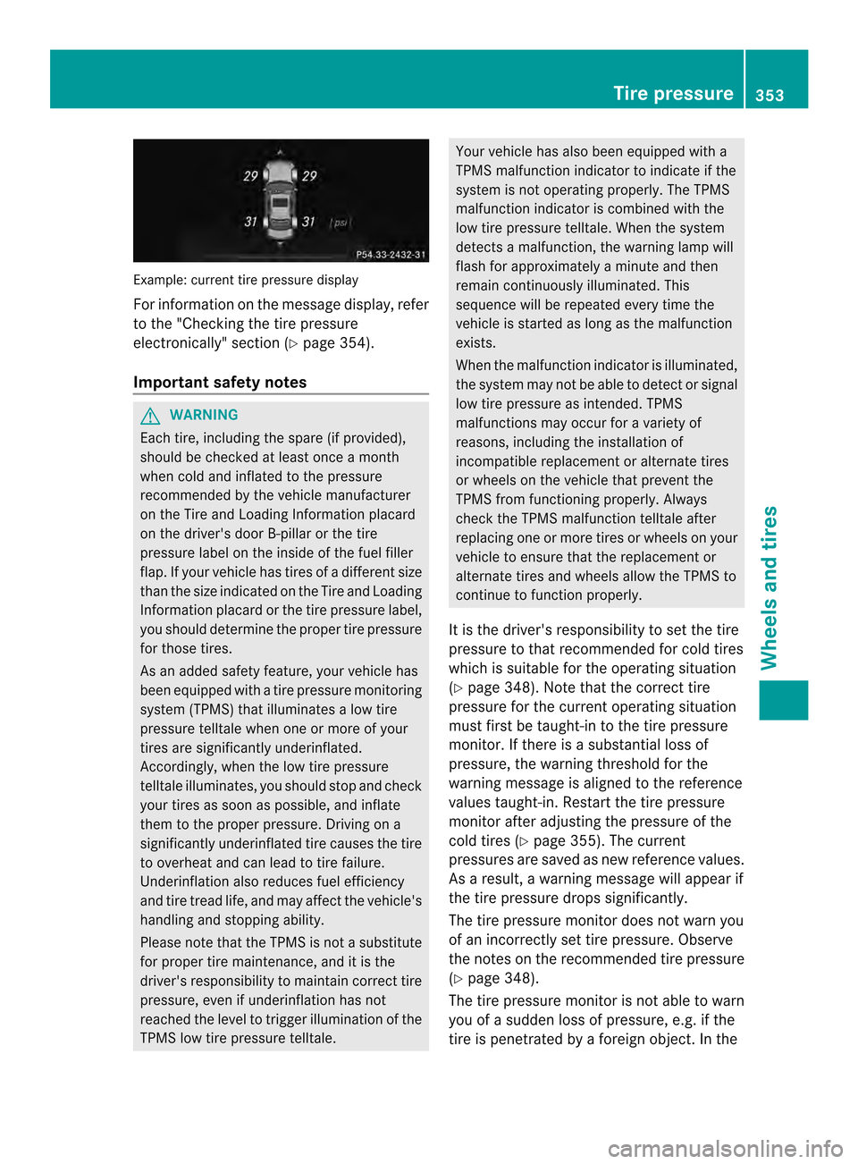
Example: current tire pressure display
For informatio
nonthe message display, refer
to the "Checking the tire pressure
electronically" section (Y page 354).
Important safety notes G
WARNING
Each tire, including the spare (if provided),
should be checked at least once a month
when cold and inflated to the pressure
recommended by the vehicle manufacturer
on the Tire and Loading Information placard
on the driver's door B-pillar or the tire
pressure label on the inside of the fuel filler
flap. If your vehicle has tires of a different size
than the size indicated on the Tire and Loading
Information placard or the tire pressure label,
you should determine the proper tire pressure
for those tires.
As an added safety feature, your vehicle has
been equipped with a tire pressure monitoring
system (TPMS) that illuminates a low tire
pressure telltale when one or more of your
tires are significantly underinflated.
Accordingly, when the low tire pressure
telltale illuminates, you should stop and check
your tires as soon as possible, and inflate
them to the proper pressure. Driving on a
significantly underinflated tire causes the tire
to overheat and can lead to tire failure.
Underinflation also reduces fuel efficiency
and tire tread life, and may affect the vehicle's
handling and stopping ability.
Please note that the TPMS is not a substitute
for proper tire maintenance, and it is the
driver's responsibility to maintain correct tire
pressure, even if underinflation has not
reached the level to trigger illumination of the
TPMS low tire pressure telltale. Your vehicle has also been equipped with a
TPMS malfunction indicator to indicate if the
system is not operating properly. The TPMS
malfunction indicator is combined with the
low tire pressure telltale. When the system
detects a malfunction, the warning lamp will
flash for approximately a minute and then
remain continuously illuminated. This
sequence will be repeated every time the
vehicle is started as long as the malfunction
exists.
When the malfunction indicator is illuminated,
the system may not be able to detect or signal
low tire pressure as intended. TPMS
malfunctions may occur for a variety of
reasons, including the installation of
incompatible replacement or alternate tires
or wheels on the vehicle that prevent the
TPMS from functioning properly. Always
check the TPMS malfunction telltale after
replacing one or more tires or wheels on your
vehicle to ensure that the replacement or
alternate tires and wheels allow the TPMS to
continue to function properly.
It is the driver's responsibility to set the tire
pressure to that recommended for cold tires
which is suitable for the operating situation
(Y page 348). Note that the correct tire
pressure for the current operating situation
must first be taught-in to the tire pressure
monitor. If there is a substantial loss of
pressure, the warning threshold for the
warning message is aligned to the reference
values taught-in. Restart the tire pressure
monitor after adjusting the pressure of the
cold tires (Y page 355). The current
pressures are saved as new reference values.
As a result, a warning message will appearif
the tire pressure drops significantly.
The tire pressure monitor does not warn you
of an incorrectly set tire pressure. Observe
the notes on the recommended tire pressure
(Y page 348).
The tire pressure monitor is not able to warn
you of a sudden loss of pressure, e.g .ifthe
tire is penetrated by a foreign object. In the Tire pressure
353Wheels and tires Z
Page 370 of 394

Components damaged in this way may fail
unexpectedly. There is a ris
kofanaccident.
Do not use power washers with circula rjet
nozzles to clean the vehicle. Have damaged
tires or chassis componentsr eplaced
immediately. Mounting
awheel
Preparing the vehicle X
Stop the vehicle on solid, non-slippery and
level ground.
X Apply the parking brake.
X Bring the front wheels into the straight-
ahead position.
X Shift the transmission to position P.
X Switch off the engine.
X Vehicles without KEYLESS-GO: remove
the SmartKey from the ignition lock.
X Vehicles with KEYLESS-GO: open the
driver's door.
The on-board electronics now have status
0.T his is the same as the SmartKey having
been removed.
X Vehicles with KEYLESS-GO: remove the
Start/Stop button from the ignition lock
(Y page 165).
X If included in the vehicle equipment,
remove the tire-change tool kit from the
vehicle (Y page 328).
X Secure the vehicle to prevent it from rolling
away. Securing the vehicle to prevent it from
rolling away If your vehicle is equipped with a wheel chock,
it can be found in the tire-change tool kit
(Y
page 328).
The folding wheel chock is an additional
safety measure to prevent the vehicle from
rolling away, for example when changing a
wheel.
X Fold both plates upwards 0002.
X Fold out lower plate 0003.
X Guide the lugs on the lower plate fully into
the openings in base plate 0023. Securing the vehicle on level ground (example:
Coupe)
X
On level ground: place chocks or other
suitable items under the front and rear of
the wheel that is diagonally opposite the
wheel you wish to change. 368
Changing
awheelWheels and tires