load capacity MERCEDES-BENZ E-Class COUPE 2011 C207 Owner's Manual
[x] Cancel search | Manufacturer: MERCEDES-BENZ, Model Year: 2011, Model line: E-Class COUPE, Model: MERCEDES-BENZ E-Class COUPE 2011 C207Pages: 344, PDF Size: 14.06 MB
Page 18 of 344
GVWR (Gross Vehicle Weight
Rating) (definition) .........................325
Increased vehicle weight due to
optional equipment (definition) ......324
Kilopascal (kPa) (definition) ...........325
Labeling (overview) ........................320
Load bearing index (definition) ......326
Load index ..................................... 323
Load index (definition) ...................325
Maximum loaded vehicle weight
(definition) ..................................... 325
Maximum load on a tire
(definition) ..................................... 325
Maximum permissible tire
pressure (definition) ....................... 325
Maximum tire load .........................318
Maximum tire load (definition) .......325
Optional equipment weight
(definition) ..................................... 326
PSI (pounds per square inch)
(definition) ..................................... 326
Replacing ....................................... 320
Service life ..................................... 305
Sidewall (definition) .......................326
Speed index (definition) .................325
Storing ........................................... 306
Structure and characteristics
(definition) ..................................... 324
Temperature .................................. 319
TIN (Tire Identification Number)
(definition) ..................................... 326
Tire bead (definition) ......................326
Tire pressure (definition) ................326
Tire pressures (recommended) ......324
Tire size (data) ............................... 327
Tire size designation, load-bearing
capacity, speed index ....................321
Tire tread ....................................... 305
Tire tread (definition) .....................326
Total load limit (definition) .............326
Traction ......................................... 319
Traction (definition) .......................326
Tread wear ..................................... 319
Uniform Tire Quality Grading
Standards ...................................... 318
Uniform Tire Quality Grading
Standards (definition) ....................324
Unladen weight (definition) ............325Wear indicator (definition) .............326
Wheel rim (definition) ....................325
Tires and wheels (important safety
information) ....................................... 304
Top Tether ............................................ 62
Towing Important safety guidelines ...........298
Installing the towing eye ................298
Removing the towing eye ...............299
Transmission position display ......... 157
Transmission positions .................... 157
Trip computer (on-board
computer) .......................................... 202
Trip odometer Calling up ....................................... 202
Resetting (on-board computer) ......203
Trunk
Automatic opening ........................... 84
Emergency release ..........................85
Important safety guidelines .............82
Locking separately ...........................84
Trunk lid
Display message ............................ 236
Trunk partition
Display message ............................ 237
General notes .................................. 96
Opening/closing .............................. 96
Turn signal (display message) ......... 223
Turn signals ....................................... 122
Type plate see Vehicle identification plate
U
Unlocking Emergency unlocking .......................82
From inside the vehicle (central
unlocking button) ............................. 81
V
Vanity mirror Sun visor ........................................ 256
Vehicle
Data acquisition ............................... 22
Emergency unlocking .......................82
Equipment ....................................... 18
Exterior view .................................... 24
16IndexBA 207 USA, CA Edition B 2011; 1; 3, en-USd2sboikeVersion: 3.0.3.62010-05-20T10:38:09+02:00 - Seite 16
Page 254 of 344
braking, or sudden maneuvers, they could be
thrown around inside the vehicle and cause
injury to vehicle occupants.
Parcel nets cannot protect transported goods
in the event of an accident.
Parcel nets are located in the front-passenger
footwell and on the left-hand side of the trunk.
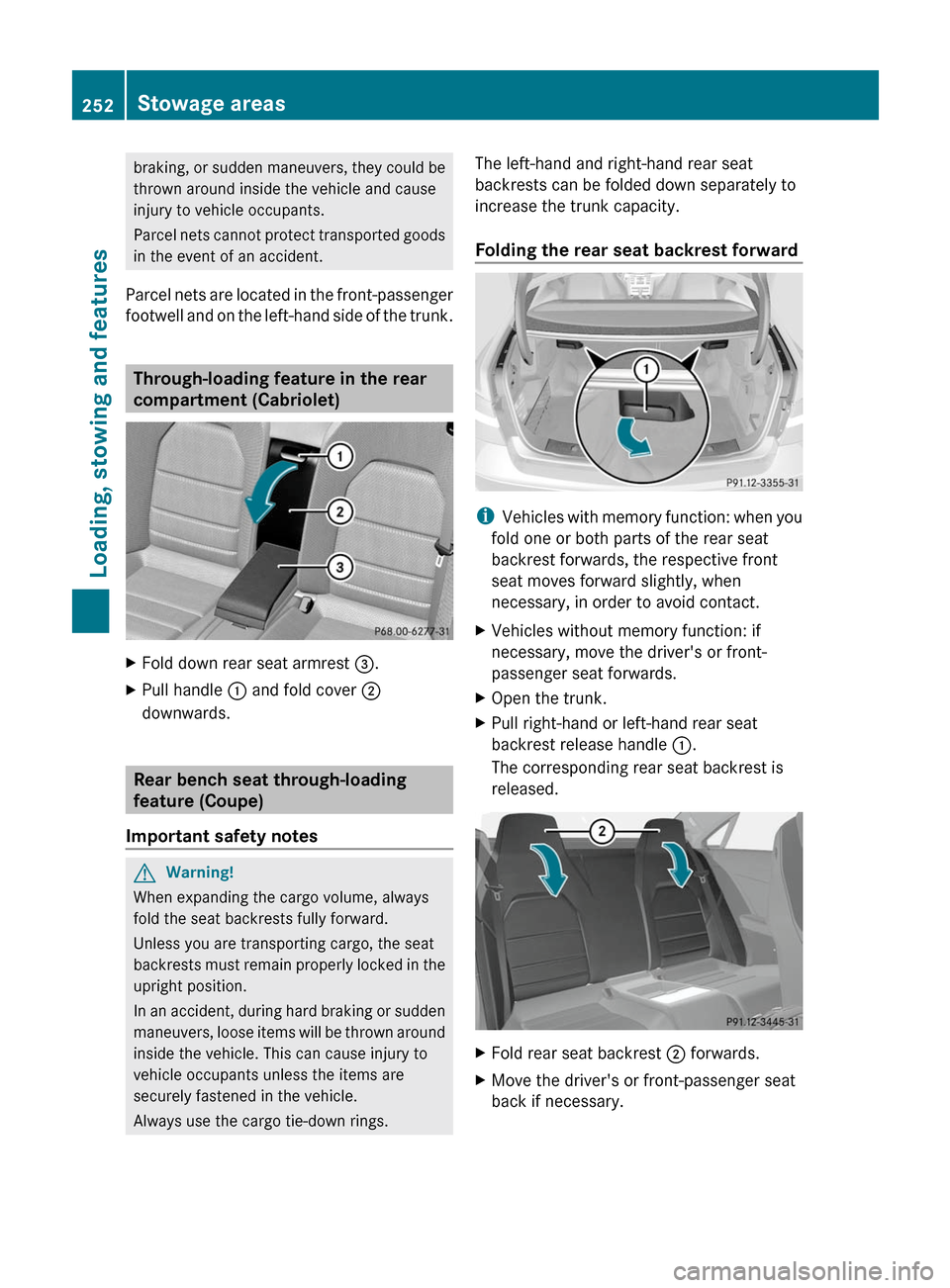
Through-loading feature in the rear
compartment (Cabriolet)
XFold down rear seat armrest =.XPull handle : and fold cover ;
downwards.
Rear bench seat through-loading
feature (Coupe)
Important safety notes
GWarning!
When expanding the cargo volume, always
fold the seat backrests fully forward.
Unless you are transporting cargo, the seat
backrests must remain properly locked in the
upright position.
In an accident, during hard braking or sudden
maneuvers, loose items will be thrown around
inside the vehicle. This can cause injury to
vehicle occupants unless the items are
securely fastened in the vehicle.
Always use the cargo tie-down rings.
The left-hand and right-hand rear seat
backrests can be folded down separately to
increase the trunk capacity.
Folding the rear seat backrest forward
iVehicles with memory function: when you
fold one or both parts of the rear seat
backrest forwards, the respective front
seat moves forward slightly, when
necessary, in order to avoid contact.
XVehicles without memory function: if
necessary, move the driver's or front-
passenger seat forwards.
XOpen the trunk.XPull right-hand or left-hand rear seat
backrest release handle :.
The corresponding rear seat backrest is
released.
XFold rear seat backrest ; forwards.XMove the driver's or front-passenger seat
back if necessary.
252Stowage areasLoading, stowing and features
BA 207 USA, CA Edition B 2011; 1; 3, en-USd2sboikeVersion: 3.0.3.62010-05-20T10:38:09+02:00 - Seite 252
Page 292 of 344
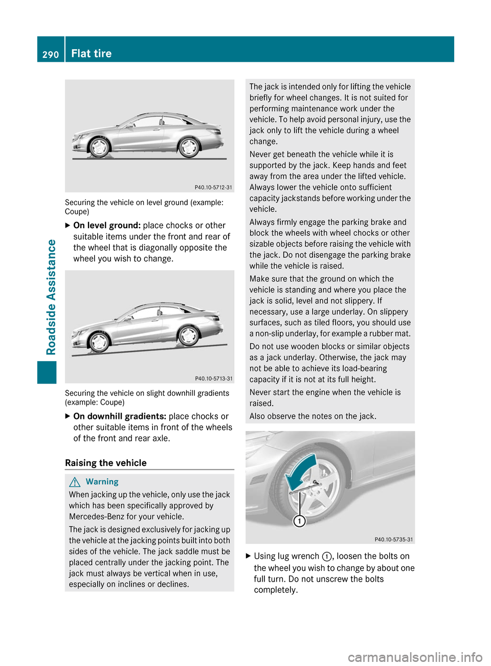
Securing the vehicle on level ground (example:Coupe)
XOn level ground: place chocks or other
suitable items under the front and rear of
the wheel that is diagonally opposite the
wheel you wish to change.
Securing the vehicle on slight downhill gradients(example: Coupe)
XOn downhill gradients: place chocks or
other suitable items in front of the wheels
of the front and rear axle.
Raising the vehicle
GWarning
When jacking up the vehicle, only use the jack
which has been specifically approved by
Mercedes-Benz for your vehicle.
The jack is designed exclusively for jacking up
the vehicle at the jacking points built into both
sides of the vehicle. The jack saddle must be
placed centrally under the jacking point. The
jack must always be vertical when in use,
especially on inclines or declines.
The jack is intended only for lifting the vehicle
briefly for wheel changes. It is not suited for
performing maintenance work under the
vehicle. To help avoid personal injury, use the
jack only to lift the vehicle during a wheel
change.
Never get beneath the vehicle while it is
supported by the jack. Keep hands and feet
away from the area under the lifted vehicle.
Always lower the vehicle onto sufficient
capacity jackstands before working under the
vehicle.
Always firmly engage the parking brake and
block the wheels with wheel chocks or other
sizable objects before raising the vehicle with
the jack. Do not disengage the parking brake
while the vehicle is raised.
Make sure that the ground on which the
vehicle is standing and where you place the
jack is solid, level and not slippery. If
necessary, use a large underlay. On slippery
surfaces, such as tiled floors, you should use
a non-slip underlay, for example a rubber mat.
Do not use wooden blocks or similar objects
as a jack underlay. Otherwise, the jack may
not be able to achieve its load-bearing
capacity if it is not at its full height.
Never start the engine when the vehicle is
raised.
Also observe the notes on the jack.
XUsing lug wrench :, loosen the bolts on
the wheel you wish to change by about one
full turn. Do not unscrew the bolts
completely.
290Flat tireRoadside Assistance
BA 207 USA, CA Edition B 2011; 1; 3, en-USd2sboikeVersion: 3.0.3.62010-05-20T10:38:09+02:00 - Seite 290
Page 318 of 344
Determining the maximum load
The following steps have been developed as required of all manufacturers under Title 49, Code
of U.S. Federal Regulations, Part 575 pursuant to the "National Traffic and Motor Vehicle
Safety Act of 1966".XStep 1: Locate the statement "The combined weight of occupants and cargo should never
exceed XXX kg or XXX lbs." on your vehicle's Tire and Loading Information placard.XStep 2: Determine the combined weight of the driver and passengers that will be traveling
in your vehicle.XStep 3: Subtract the combined weight of the driver and passengers from XXX kilograms or
XXX lbs.XStep 4: The resulting figure equals the available amount of cargo and luggage load capacity.
For example, if the "XXX" amount equals 1400 lbs and there will be five 150 lbs passengers
in your vehicle, the amount of available cargo and luggage load capacity is 650 lbs (1400 -
750 (5 x 150) = 650 lbs).X Step 5: Determine the combined weight of luggage and cargo being loaded on the vehicle.
For reasons of safety, that weight must not exceed the available cargo and luggage cargo
capacity calculated in step 4.XStep 6 (if applicable): If you intend to tow a trailer behind your vehicle, the load on the
trailer is transferred to your vehicle. Consult this Operator's Manual to determine how this
reduces the available cargo and luggage load capacity of your vehicle ( Y page 318).
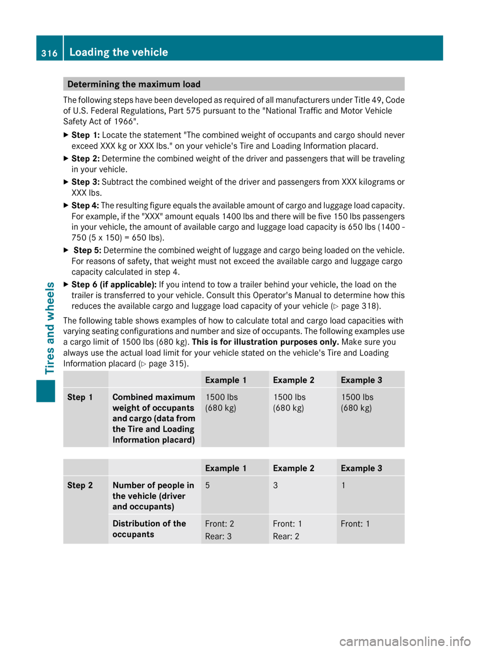
The following table shows examples of how to calculate total and cargo load capacities with
varying seating configurations and number and size of occupants. The following examples use
a cargo limit of 1500 lbs (680 kg). This is for illustration purposes only. Make sure you
always use the actual load limit for your vehicle stated on the vehicle's Tire and Loading
Information placard ( Y page 315).
Example 1Example 2Example 3Step 1Combined maximum
weight of occupants
and cargo (data from
the Tire and Loading
Information placard)1500 lbs
(680 kg)1500 lbs
(680 kg)1500 lbs
(680 kg)Example 1Example 2Example 3Step 2Number of people in
the vehicle (driver
and occupants)531Distribution of the
occupantsFront: 2
Rear: 3Front: 1
Rear: 2Front: 1316Loading the vehicleTires and wheels
BA 207 USA, CA Edition B 2011; 1; 3, en-USd2sboikeVersion: 3.0.3.62010-05-20T10:38:09+02:00 - Seite 316
Page 322 of 344
car tires must meet under Federal Motor
Vehicle Safety Standard No. 109. Grades B
and A represent higher levels of performance
on the laboratory test wheel than the
minimum required by law.
Interchanging the wheels
GWarning
Rotate front and rear wheels only if the tires
are of the same dimension.
If your vehicle is equipped with mixed-size
tires (different tire dimensions front vs. rear),
tire rotation is not possible.
GWarning!
Have the tightening torque checked after
changing a wheel. Wheels could become
loose if not tightened with a torque of
96 lb-ft (130 Nm).
Only use genuine Mercedes-Benz wheel bolts
specified for your vehicle's rims.
The wear patterns on the front and rear tires
differ, depending on the operating conditions.
Rotate the wheels before a clear wear pattern
has formed on the tires. Front tires typically
wear more on the shoulders and the rear tires
in the center.
If your vehicle's tire configuration allows, you
can rotate the wheels according to the
intervals in the tire manufacturer's warranty
book in your vehicle documents. If no
warranty book is available, the tires should be
rotated every 3000 to 6000 miles
(5000 to 10000 km), or earlier if tire wear
requires. Do not change the direction of
wheel rotation.
Clean the contact surfaces of the wheel and
the brake disc thoroughly every time a wheel
is rotated. Check the tire pressures.
Information on changing a wheel and
mounting the spare wheel ( Y page 289).
Tire labeling
Overview of tire labeling
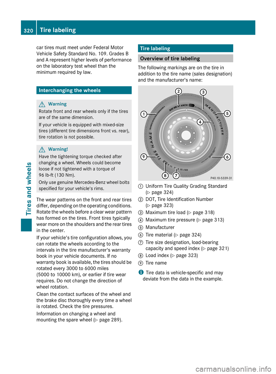
The following markings are on the tire in
addition to the tire name (sales designation)
and the manufacturer's name:
:Uniform Tire Quality Grading Standard
( Y page 324);DOT, Tire Identification Number
( Y page 323)=Maximum tire load ( Y page 318)?Maximum tire pressure ( Y page 313)AManufacturerBTire material ( Y page 324)CTire size designation, load-bearing
capacity and speed index ( Y page 321)DLoad index ( Y page 323)ETire name
i
Tire data is vehicle-specific and may
deviate from the data in the example.
320Tire labelingTires and wheels
BA 207 USA, CA Edition B 2011; 1; 3, en-USd2sboikeVersion: 3.0.3.62010-05-20T10:38:09+02:00 - Seite 320
Page 323 of 344
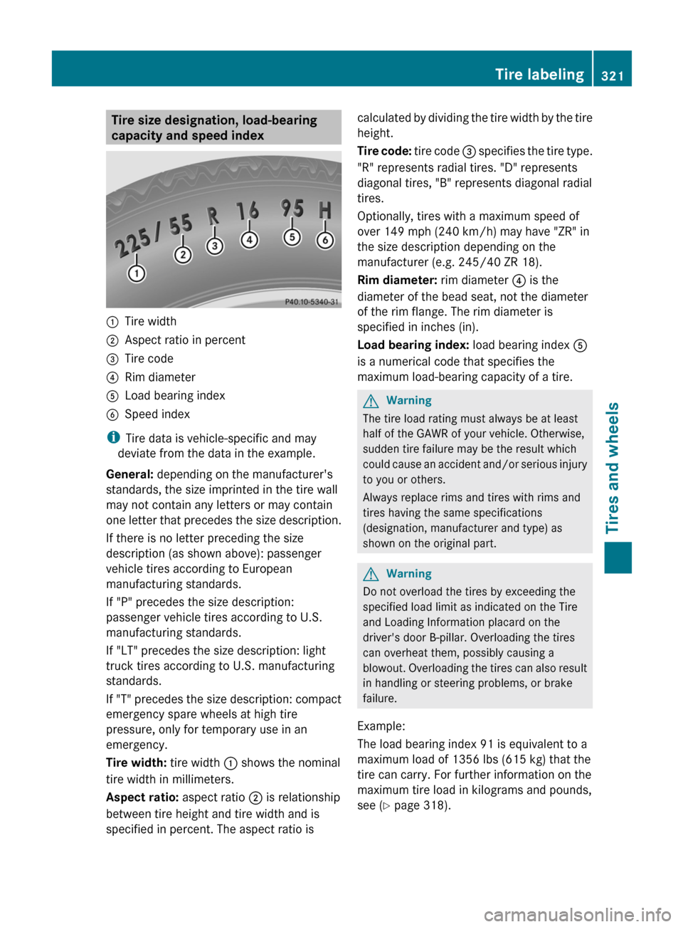
Tire size designation, load-bearing
capacity and speed index:Tire width;Aspect ratio in percent=Tire code?Rim diameterALoad bearing indexBSpeed index
i Tire data is vehicle-specific and may
deviate from the data in the example.
General: depending on the manufacturer's
standards, the size imprinted in the tire wall
may not contain any letters or may contain
one letter that precedes the size description.
If there is no letter preceding the size
description (as shown above): passenger
vehicle tires according to European
manufacturing standards.
If "P" precedes the size description:
passenger vehicle tires according to U.S.
manufacturing standards.
If "LT" precedes the size description: light
truck tires according to U.S. manufacturing
standards.
If "T" precedes the size description: compact
emergency spare wheels at high tire
pressure, only for temporary use in an
emergency.
Tire width: tire width : shows the nominal
tire width in millimeters.
Aspect ratio: aspect ratio ; is relationship
between tire height and tire width and is
specified in percent. The aspect ratio is
calculated by dividing the tire width by the tire
height.
Tire code: tire code = specifies the tire type.
"R" represents radial tires. "D" represents
diagonal tires, "B" represents diagonal radial
tires.
Optionally, tires with a maximum speed of
over 149 mph (240 km/h) may have "ZR" in
the size description depending on the
manufacturer (e.g. 245/40 ZR 18).
Rim diameter: rim diameter ? is the
diameter of the bead seat, not the diameter
of the rim flange. The rim diameter is
specified in inches (in).
Load bearing index: load bearing index A
is a numerical code that specifies the
maximum load-bearing capacity of a tire.GWarning
The tire load rating must always be at least
half of the GAWR of your vehicle. Otherwise,
sudden tire failure may be the result which
could cause an accident and/or serious injury
to you or others.
Always replace rims and tires with rims and
tires having the same specifications
(designation, manufacturer and type) as
shown on the original part.
GWarning
Do not overload the tires by exceeding the
specified load limit as indicated on the Tire
and Loading Information placard on the
driver's door B-pillar. Overloading the tires
can overheat them, possibly causing a
blowout. Overloading the tires can also result
in handling or steering problems, or brake
failure.
Example:
The load bearing index 91 is equivalent to a
maximum load of 1356 lbs (615 kg) that the
tire can carry. For further information on the
maximum tire load in kilograms and pounds,
see ( Y page 318).
Tire labeling321Tires and wheelsBA 207 USA, CA Edition B 2011; 1; 3, en-USd2sboikeVersion: 3.0.3.62010-05-20T10:38:09+02:00 - Seite 321Z
Page 327 of 344
Wheel rim
The part of the wheel on which the tire is
mounted.
GAWR (Gross Axle Weight Rating)
The GAWR is the maximum gross axle weight
rating. The actual load on an axle must never
exceed the gross axle weight rating. The
gross axle weight rating can be found on the
vehicle identification plate on the B-pillar on
the driver's side.
Speed index
The speed index is part of the tire
identification. Specifies the speed range for
which the tire is approved.
GVW (Gross Vehicle Weight)
The gross vehicle weight includes the weight
of the vehicle including fuel, tools, the spare
wheel, accessories installed, occupants,
luggage and the drawbar noseweight if
applicable. The gross vehicle weight must not
exceed the gross vehicle weight rating GVWR
as specified on the vehicle identification plate
on the B-pillar on the driver's side.
GVWR (Gross Vehicle Weight Rating)
The GVWR is the maximum permissible gross
weight of a fully loaded vehicle (the weight of
the vehicle including all accessories,
occupants, fuel, luggage and the drawbar
noseweight if applicable). The gross vehicle
weight rating is specified on the vehicle
identification plate on the B-pillar on the
driver's side.
Maximum weight of the laden vehicle
The maximum weight is the sum of the
unladen weight of the vehicle, the weight of
the accessories, the maximum load and the
weight of the optional equipment installed at
the factory.
Kilopascal (kPa)
Metric unit for tire pressure. 6.9 kPa is the
equivalent of 1 psi. Another unit for tire
pressure is bar. 100 kilopascal (kPa) is the
equivalent of 1 bar.
Load index
In addition to the load bearing index, the load
index may also be imprinted on the sidewall
of the tire. This specifies the load bearing
capacity more precisely.
Unladen weight
The weight of a vehicle with standard
equipment including the maximum capacity
of fuel, oil and coolant. It also includes the air-
conditioning system and optional equipment
if these are installed on the vehicle, but does
not include passengers or luggage.
Maximum tire load
The maximum tire load in kilograms or
pounds is the maximum weight for which a
tire is approved.
Maximum permissible tire pressure
Maximum permissible tire pressure for one
tire.
Maximum load on one tire
Maximum load on one tire. This is calculated
by dividing the maximum axle load of one axle
by two.
Definitions for tires and loading325Tires and wheelsBA 207 USA, CA Edition B 2011; 1; 3, en-USd2sboikeVersion: 3.0.3.62010-05-20T10:38:09+02:00 - Seite 325Z
Page 328 of 344

PSI (pounds per square inch)
Standard unit of measurement for tire
pressure.
Aspect ratio
Relationship between tire height and tire
width in percent.
Tire pressure
Pressure inside the tire applying an outward
force to every square inch of the tire's
surface. The tire pressure is specified in
pounds per square inch (psi), in kilopascal
(kPa) or in bar. The tire pressure should only
be corrected when the tires are cold. For this,
the vehicle must have been stationary for at
least three hours or not have traveled more
than 1.6 km (1 mile) in this time.
Tire tread
The part of the tire that comes into contact
with the road.
Tire bead
The tire bead contains steel wire which is
bound by steel cords that hold the tire on the
wheel rim.
Sidewall
The part of the tire between the tread and the
tire bead.
Weight of optional extras
The combined weight of those optional extras
that weigh more than the replaced standard
part and more than 2.3 kilograms (5 lbs).
These optional extras, such as high-
performance brakes, level control, a roof rack
or a high-performance battery, are not
included in the unladen weight and the weight
of the accessories.
TIN (Tire Identification Number)
A unique identification number which can be
used by a tire manufacturer to identify tires,
for example for a product recall, and thus
identify the purchasers. The TIN is made up
of the manufacturer's identity code, tire size,
tire type code and the manufacturing date.
Load bearing index
The load bearing index (also load index) is a
code that contains the maximum load bearing
capacity of a tire.
Traction
Traction is the result of friction between the
tires and the road surface.
Wear indicator
Narrow bars (tread wear bars) that are
distributed over the tire tread. If the tire tread
is level with the bars, the wear limit of 1
/ 16 in
(1.6 mm) has been reached.
Distribution of the vehicle occupants
Distribution of vehicle occupants over
designated seat positions in a vehicle.
Maximum permissible payload
weight
Nominal load and luggage load plus
68 kilograms (150 lb) multiplied by the
number of seats in the vehicle.
326Definitions for tires and loadingTires and wheels
BA 207 USA, CA Edition B 2011; 1; 3, en-USd2sboikeVersion: 3.0.3.62010-05-20T10:38:09+02:00 - Seite 326