length MERCEDES-BENZ E-CLASS COUPE 2020 Owners Manual
[x] Cancel search | Manufacturer: MERCEDES-BENZ, Model Year: 2020, Model line: E-CLASS COUPE, Model: MERCEDES-BENZ E-CLASS COUPE 2020Pages: 473, PDF Size: 8.5 MB
Page 18 of 473

1
Adjusts the seats electrically ŌåÆ
98
2 Switches the seat heating on/off ŌåÆ
103
3 Switches the seat ventilation on/o ff ŌåÆ
105
4 Switches AIRSCARF on/off ŌåÆ
105
5 &%Loc ks/unloc kstheve hicle ŌåÆ
74
6 Opens/closes the boot lid ŌåÆ
78
7 Operating the outside mir rors ŌåÆ
137
8 W Opens/closes theright side window ŌåÆ
83
9 W Opens/closes there ar right side winŌĆÉ
dow ŌåÆ
83
A Child saf ety lock forth ere ar side wind ows ŌåÆ
68
B W Opens/closes there ar left side wind owŌåÆ
83 C
W Opens/closes the left side window ŌåÆ
83
D Opens the door ŌåÆ
74
E Operates the memory function ŌåÆ
11 0
F Sets the seat fore -and-aft position ŌåÆ
97
G Adjusts the seat cushion length ŌåÆ
97
H Adjusts the 4-w aylumbar support ŌåÆ
98
I Configuring the seat settings ŌåÆ
100
J Adjusts the head restra ints ŌåÆ
98
K Adjusts the seat cushion inclination ŌåÆ
97
L Adjusting the seat height ŌåÆ
97
M Adjusts the seat backrest inclination ŌåÆ
97 At
aglance ŌĆō Door control panel and seat adjustment 15
Page 48 of 473

fo
rm ed on the doors or door trim, or if the
doors are damaged. #
Never modify the doors or parts of the
doors. #
Alw ays ha vewo rkon the doors or door
trim car ried out at a qualified specialist
wo rkshop. &
WARNING Risk of inju rydue todeplo yed
airbag
A deplo yed airbag no longer of fers any proŌĆÉ
te ction. #
Have theve hicle towe dto aqu alified
specialist workshop in order tohave the
deplo yed airbag replaced. Ha
ve deplo yed airbags replaced immediately. St
atus of the front passenger front airbag Fu
nction of the automatic front passenger
airbag shu toff
The automatic front passenger front airbag shutŌĆÉ
off is able todetect whe ther the front passenger seat is occupied
bya person or a child restra int
sy stem. The front passenger airbag is enabled or
disabled accordingly. &
WARNING Risk of inju ryor death due to
objects under the co-driver seat
Objects trapped under the co-driver seat can
inter fere with the function of the automatic
co-driver airbag shutoff or damage the sysŌĆÉ
te m. #
Do not store any objects under the co-
driver seat. #
When the co-driver seat is occupied,
make sure that no objects are trapped
under the co-driver seat. When
fitting a child restra int sy stem tothe front
passenger seat, alw ays make sure of thefo llowŌĆÉ
ing:
R Ensure that thech ild restra int sy stem is posiŌĆÉ
tioned cor rectly (/ page 56).
R Alw ays comply with thech ild restra int sysŌĆÉ
te m manufacturer's ins tallation instructions. R
Never place objects (e.g. cushions) under or
behind thech ild restra int sy stem.
R Fully retract the seat cushion length adjustŌĆÉ
ment.
R The entire base of thech ild restra int sy stem
must alw aysre st on the sitting sur face of the
front passenger seat.
R The backrest of thefo rw ard-facing child
re stra int sy stem must, as far as possible, be
re sting on the seat backrest of the front
passenger seat.
R The child restra int sy stem must not touch the
ro of or be put under stra in by the head
re stra ints. Adjust the seat backrest inclinaŌĆÉ
tion and the head restra int setting accordŌĆÉ
ing ly. &
WARNING Risk of inju ryor death due to
objects between the seat sur face and
th ech ild restra int sy stem
Objects between the sitting sur face and the
ch ild restra int sy stem could af fect the funcŌĆÉ
tion of the automatic front passenger airbag
shutoff. Occupant saf
ety45
Page 51 of 473
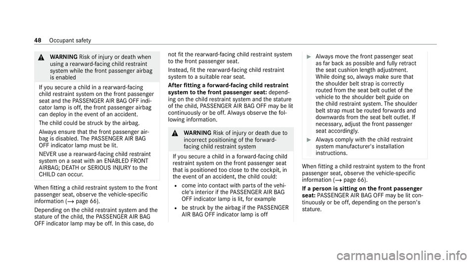
&
WARNING Risk of inju ryor death when
using a rear wa rd-facing child restra int
sy stem while the front passenger airbag
is enabled
If yo u secure a child in a rear wa rd-facing
ch ild restra int sy stem on the front passenger
seat and thePA SSENGER AIR BAG OFF indiŌĆÉ
cator lamp is off, the front passenger airbag
can deploy in theev ent of an accident.
The child could be stru ck bythe airbag.
Alw ays ensure that the front passenger airŌĆÉ
bag is disabled. The PASSENGER AIR BAG
OFF indicator lamp must be lit.
NEVER use a rear wa rd-facing child restra int
sy stem on a seat with an ENABLED FRONT
AIRB AG; DEAT H or SERIOUS INJU RYtothe
CH ILD can occur. When
fitting a child restra int sy stem tothe front
passenger seat, obser vetheve hicle-specific
information (/ page 66).
Depending on thech ild restra int sy stem and the
st ature of thech ild, thePA SSENGER AIR BAG
OFF indicator lamp may be off. In this case, do not
fit th ere ar wa rd-facing child restra int sy stem
to the front passenger seat.
Ins tead, fit th ere ar wa rd-facing child restra int
sy stem toa suitable rear seat.
Af terfitting a forw ard-facing child restra int
sy stem tothe front passenger seat: dependŌĆÉ
ing on thech ild restra int sy stem and thest ature
of thech ild, PASSENGER AIR BAG OFF may be lit
continuously or be off. Alw ays obser vethefo lŌĆÉ
lowing information. &
WARNING Risk of inju ryor death due to
incor rect positioning of thefo rw ard-
fa cing child restra int sy stem
If yo u secure a child in a forw ard-facing child
re stra int sy stem on the front passenger seat
th at is positioned too close tothe cockpit, in
th eev ent of an accident, thech ild could:
R come into con tact wi thparts of theve hiŌĆÉ
cle's interior if thePA SSENGER AIR BAG
OFF indicator lamp is lit, forex ample
R bestru ck bythe airbag if thePA SSENGER
AIR BAG OFF indicator lamp is off #
Alw ays mo vethe front passenger seat
as far back as possible and fully retract
th e seat cushion length adjustment.
While doing so, alw ays make sure that
th e shoulder belt stra p is cor rectly
ro uted from the seat belt outlet of the
ve hicle tothe shoulder belt guide on
th ech ild restra int sy stem. The shoulder
belt stra p must be routed forw ards and
down wards from the seat belt outlet. If
necessar y,adjust the front passenger
seat accordingly. #
Alw ays comply with thech ild restra int
sy stem manufacturer's ins tallation
instructions. When
fitting a child restra int sy stem tothe front
passenger seat, obser vetheve hicle-specific
information (/ page 66).
If a person is sitting on the front passenger
seat: PASSENGER AIR BAG OFF may be lit conŌĆÉ
tinuously or be off, depending on the person's
st ature. 48
Occupant saf ety
Page 70 of 473
passenger airbag must alw
ays be disabled.
This is only the case if thePA SSENGER AIR
BA G OFF indicator lamp is lit continuously
(/ page 47).
R Ifth ePA SSENGER AIR BAG OFF indicator
lamp is off, the front passenger airbag is enaŌĆÉ
bled. The front passenger airbag may deploy
during an accident.
Securing thech ild restra int sy stem with the
seat belt on the front passenger seat
When fitting a belt-secu redch ild restra int sysŌĆÉ
te m on the front passenger seat, alw ays obser ve
th efo llowing:
O Obser
vethe no tes on rear wa rd-facing and
fo rw ard-facing child restra int sy stems on
th e front passenger seat (/ page 66).
O Obser
vethech ild restra int sy stem manufacŌĆÉ
turer's ins tallation and operating instrucŌĆÉ
tions.
O Fo
r a child restra int sy stem in the "UniverŌĆÉ
sal" or "Semi-Universal" categor y,make
sure that the sy stem has been appr ovedfor
th eve hicle seat. Obser
vethe no tes under "Suitability of
seats for attaching belt-secu redch ild
re stra int sy stems" (/ page 63).
O When using a
forw ard-facing child restra int
sy stem in category I: remo vethe head
re stra int from there spective seat, if possiŌĆÉ
ble.
Af terth ech ild restra int sy stem has been
re mo ved, replace the head restra ints again
immediately and adjust them cor rectly.
O The ba
ckrest of thefo rw ard-facing child
re stra int sy stem must, as far as possible, be
re sting on the seat backrest of the front
passenger seat.
O Fo
r cer tain child restra int sy stems in weight
category II or III, there may be restrictions
on the maximum size setting, e.g. due to
possible con tact wi th thero of.
O The
child restra int sy stem must not be put
under stra in between thero of and the seat
cushion and/or be fitted facing the wrong
direction. O
The
child restra int sy stem must not be put
under stra in by the head restra int. Adjust
th e head restra ints as appropriate.
O Ne
ver place objects (e.g. cushions) under or
behind thech ild restra int sy stem. #
Set the front passenger seat as far back as
possible and mo vethe seat into the highest
position if possible. #
Fully retract the seat cushion length adjustŌĆÉ
ment. #
Adjust the seat cushion inclination so that
th e front edge of the seat cushion is in the
highest position and there ar edge of the
seat cushion is in the lo west position. #
Set the seat backrest tothe most vertical
position possible. #
Installth ech ild restra int sy stem.
The entire base of thech ild restra int sy stem
must alw aysre st on the sitting sur face of the
front passenger seat. #
Alw ays make sure that the shoulder belt
st ra p is cor rectly routed from the seat belt Occupant saf
ety67
Page 85 of 473
When making
the kicking mo vement, make sure
th at you are standing firm ly on the ground. Yo u
could otherwise lose your balance, e.g. on ice.
Obser vethefo llowing no tes:
R The key is behind theve hicle.
R Stand at least 30 cm away from theve hicle
while per form ing the kicking mo vement.
R Do not come into contact with the bumper
while making the kicking mo vement.
R Do not car ryout the kicking mo vement too
slowl y.
R The kicking mo vement must be towa rdsthe
ve hicle and back again. 1
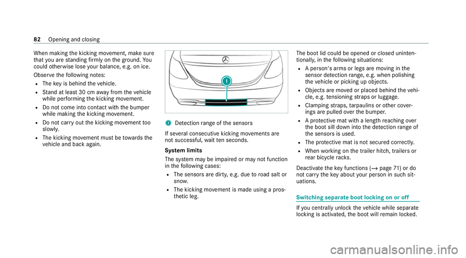
Detection range of the sensors
If se veral consecutive kicking mo vements are
not successful, waitte n seconds.
Sy stem limits
The sy stem may be impaired or may not function
in thefo llowing cases:
R The sensors are dirty, e.g. due toroad salt or
sn ow.
R The kicking mo vement is made using a prosŌĆÉ
th etic leg. The boot lid could be opened or closed unin
tenŌĆÉ
tionally, in thefo llowing situations:
R A person's arms or legs are moving in the
sensor de tection range, e.g. when polishing
th eve hicle or picking up objects.
R Objects are mo ved or placed behind theve hiŌĆÉ
cle, e.g. tensioning stra ps or luggage.
R Clamping stra ps, tarp aulins or other co verŌĆÉ
ings are pulled overth e bumper.
R A pr otective mat with a length reaching over
th e boot sill down into the de tection range of
th e sensors is used.
R The pr otective mat is not secured cor rectl y.
R When working on the trailer hitch, trailers or
re ar bicycle rack s.
Deactivate theke y functions ( /page 71) or do
not car rytheke y about your person in such sitŌĆÉ
uations. Swit
ching separate boot locking on or off If
yo u centrally unlo cktheve hicle while separate
locking is activated, the boot will remain loc ked. 82
Opening and closing
Page 100 of 473
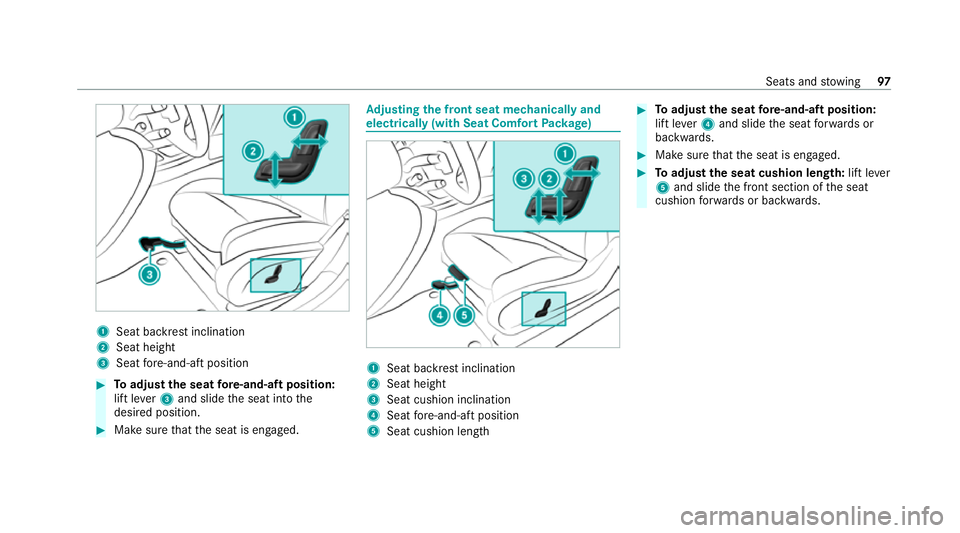
1
Seat ba ckrest inclination
2 Seat height
3 Seat fore -and-aft position #
Toadjust the seat fore -and-aft position:
lift le ver3 and slide the seat into the
desired position. #
Make sure that the seat is engaged. Ad
justing the front seat mechanically and
electrically (with Seat Comfort Package) 1
Seat backrest inclination
2 Seat height
3 Seat cushion inclination
4 Seat fore -and-aft position
5 Seat cushion length #
Toadjust the seat fore -and-aft position:
lift le ver4 and slide the seat forw ards or
backwards. #
Make sure that the seat is engaged. #
Toadjust the seat cushion length: lift lever
5 and slide the front section of the seat
cushion forw ards or backwards. Seats and
stowing 97
Page 101 of 473
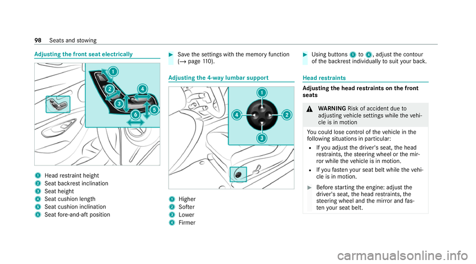
Ad
justing the front seat electrically 1
Head restra int height
2 Seat backrest inclination
3 Seat height
4 Seat cushion length
5 Seat cushion inclination
6 Seat fore -and-aft position #
Save the settings with the memory function
(/ page 110). Ad
justing the 4-w aylumbar support 1
Higher
2 Softer
3 Lower
4 Firmer #
Using buttons 1to4 , adjust the conto ur
of the backrest individually tosuit your bac k. Head
restra ints Ad
justing the head restra ints on the front
seats &
WARNING Risk of accident due to
adjusting vehicle settings while theve hiŌĆÉ
cle is in motion
Yo u could lose cont rol of theve hicle in the
fo llowing situations in particular:
R Ifyo u adjust the driver's seat, the head
re stra ints, thesteering wheel or the mirŌĆÉ
ro r while theve hicle is in motion.
R Ifyo ufast enyour seat belt while theve hiŌĆÉ
cle is in motion. #
Before starting the engine: adjust the
driver's seat, the head restra ints, the
st eering wheel and the mir ror and fasŌĆÉ
te nyo ur seat belt. 98
Seats and stowing
Page 214 of 473
R
From appr ox. 30 km/h: theve hicle is adjusŌĆÉ
te dto normal le vel,re ga rdless of drive proŌĆÉ
gr am. Park
ing Assist PARKTRONIC Fu
nction of Parking Assist PARKTRONIC
Pa rking Assist PARKTRONIC is an electronic
parking assi stance sy stem which monitors the
area sur rounding your vehicle and sho wsyouthe
dis tance between theve hicle and a de tected
obs tacle visually and audibly.
Pa rking Assist PARKTRONIC is on lyan aid. It is
not a substitute foryo ur attention tothe surŌĆÉ
ro undings. The responsibility for safe manoeuŌĆÉ
vring and parking remains with you. Make sure
th at there are no persons, animals or objects in
th e manoeuvring area while manoeuvring and
parking in/exiting parking spaces.
The passive side impact pr otection also warns
yo u of obs tacles tothe side. During the parking
procedure or manoeuvring, objects are de tected
as theve hicle drives past. If yousteer in the
direction of a de tected obs tacle and there is a
ri sk of a lateral collision, a warning is issued. In order
for an object on the side tobe de tected,
th e sensors in the front and rear bumper must
fi rs t de tect the object while you are driving past
it.
In order for front or rear obs tacles tothe side to
be displa yed, theve hicle must firs t tr ave l a disŌĆÉ
ta nce of at least half a vehicle length. Once the
ve hicle has tr avelled one vehicle length, obs taŌĆÉ
cles on all sides can be shown.
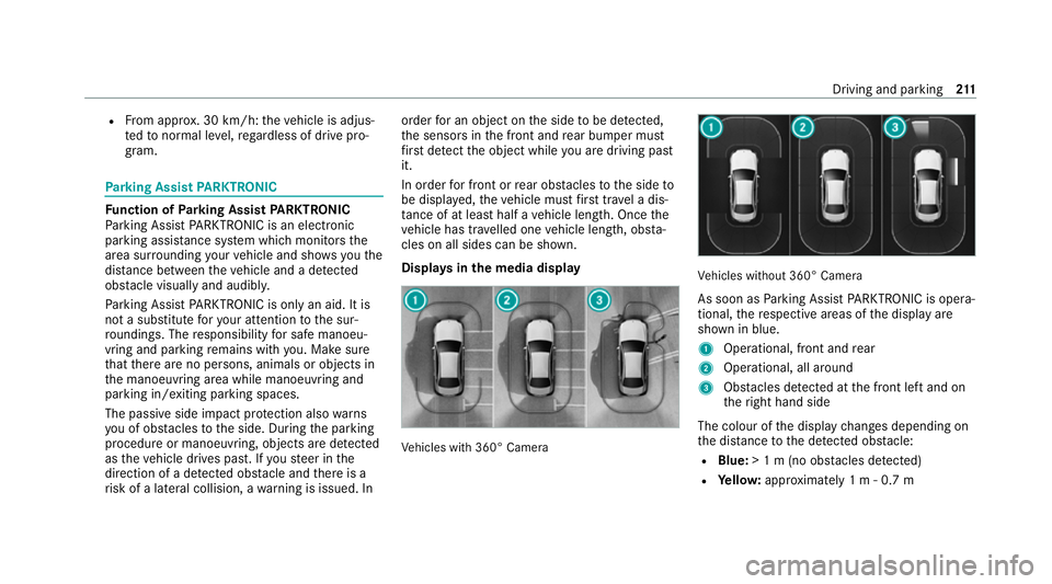
Displa ysinthe media display Ve
hicles with 360┬░ Camera Ve
hicles without 360┬░ Camera
As soon as Parking Assist PARKTRONIC is operaŌĆÉ
tional, there spective areas of the display are
shown in blue.
1 Operational, front and rear
2 Operational, all around
3 Obstacles de tected at the front left and on
th eright hand side
The colour of the display changes depending on
th e dis tance tothe de tected obs tacle:
R Blue: > 1 m (no obs tacles de tected)
R Yello w: appr oximately 1 m - 0.7 m Driving and parking
211
Page 230 of 473
Ac
tivating/deactivating manoeuv ring assisŌĆÉ
tant
Multimedia sy stem:
4 ┬® 5
Settings 5
Assistance
5 Camera & parking #
Activate/deactivate Manoeuvring assistance.
% For Drive AwayAssi st (/ page 225) tofuncŌĆÉ
tion, manoeuvring assi stant must be active. AT
TENTION ASSI ST Fu
nction of ATTENTION ASSI ST
AT TENTION ASSIST assists you on long, mon otoŌĆÉ
nous journe ys, e.g. on mo torw ays and trunk
ro ads. If ATTENTION ASSIST de tects indicators
of fatigue or increasing lapses in concentration
on the part of the driver, it suggests taking a
brea k.
AT TENTION ASSIST is only an aid. It cannot
alw ays de tect fatigue or lapses in concentration
in time. The sy stem is not a substitute for a well-
re sted and attentive driver. On long journe ys,
ta ke regular breaks in good time that allow for
adequate recuperation. Yo
u can choose between two settings:
R Standard: normal sy stem sensitivity.
R Sensitive: higher system sensitivity. The
driver is warned earlier and the attention
le ve l de tected byATTENTION ASSIST is adapŌĆÉ
te d according ly.
If dr owsiness or increasing lapses in concentraŌĆÉ
tion are de tected, theATTENTION ASSIST: Take
a break! warning appears in the Instrument DisŌĆÉ
pla y.Yo u can ackn owledge the message and
tak e a break where necessar y.Ifyo u do not take
a break and ATTENTION ASSIST continues to
de tect increasing lapses in concentration, you
will be warned again af ter a minimum of
15 minutes. Yo
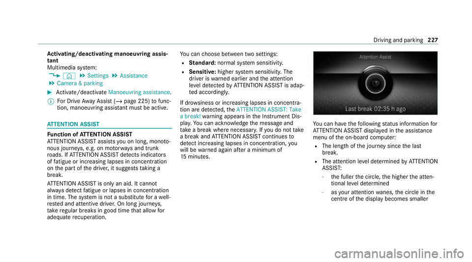
u can ha vethefo llowing status information for
AT TENTION ASSIST displa yed in the assis tance
menu of the on-board computer:
R The length of the journey since the last
break.
R The attention le vel de term ined byATTENTION
ASSIS T:
- the fuller the circle, the higher the attenŌĆÉ
tional le vel de term ined
- asyour attention wanes, the circle in the
centre of the display becomes smaller Driving and parking
227
Page 466 of 473
U
Un locking setting ...................................... 71
Up dates
Impor tant sy stem updates .................. 262
USB port Rear .................................................... .119 V
Ve hicle ...................................................... 154
Ac tivating/deactivating standby
mode .................................................. .183
Ad ditional door lock .............................. 73
Collision de tection (pa rking) ................ 181
Cor rect use ........................................... 30
Data acquisition ..................................... 31
Data storage .......................................... 31
Diagno stics connection ........................ .28
Equipment ............................................. 22
Implied warranty .................................... 31
Locking (auto matically) ......................... .76
Locking (Digital Vehicle Keyst icke r) ..... .75
Locking (from inside) ............................. 74
Locking (KEYLESS-GO) ..........................75
Locking/unlocking (emergency key) .... .77 Lo
we ring ............................................. 345
Medical aids .......................................... 30
Pa rking up .......................................... .182
QR code rescue card ............................. 31
Qualified specialist workshop ................29
Ra ising ................................................ .341
REA CHregulation ..................................30
Re gistration ...........................................29
St andby mode function ...................... .182
St arting (Digital Vehicle Keyst icke r) .... 154
St arting (eme rgency operation
mode) .................................................. 154
St arting (Remo teOnline) ..................... 15 5
St arting (s tart/s top button) ................ 15 3
Switching off (s tart/s top button) .........1 76
To wing ................................................ .243
Un locking (Digital Vehicle Keyst icke r) ... 75
Un locking (from inside) .......................... 74
Un locking (KEYLESS-GO) ...................... .75
Ve ntilating (co nvenience opening) ......... 85
Ve hicle data
Displ aying (DYNAMIC SELECT) ............ 16 6
Ro of load ............................................. 362
Ve hicle height ...................................... 361
Ve hicle length ...................................... 361 Ve
hicle width ....................................... 361
Wheelbase ...........................................3 61
Ve hicle dimensions ................................. 361
Ve hicle identification number
see VIN
Ve hicle identification plate .................... 349
EU general operating pe rmit number .. 349
Pa int code .......................................... .349
Pe rm issible axle load .......................... .349
Pe rm issible gross mass ...................... .349
VIN ...................................................... 349
Ve hicle interior
Cooling or heating (Remo teOnline) ..... 15 5
Ve hicle key
see Key
Ve hicle maintenance
see ASS YST PLUS
Ve hicle tool kit ........................................ .312
TIREFIT kit ............................................ 312
To wing eye .......................................... 326
Ve ntilating
Con venience opening ............................ 85 Index
463