sensor MERCEDES-BENZ E-CLASS SALOON 2011 Workshop Manual
[x] Cancel search | Manufacturer: MERCEDES-BENZ, Model Year: 2011, Model line: E-CLASS SALOON, Model: MERCEDES-BENZ E-CLASS SALOON 2011Pages: 409, PDF Size: 10.47 MB
Page 333 of 409
X
Clean the plastic lenses of the exterior
lighting using a wet sponge and a mild
cleaning agent, e.g. Mercedes-Ben zcar
shampoo. Or clean the exterior lighting
with cleaning cloths.
Cleaning the mirror turn signals !
Only use cleaning agents or cleaning
cloths that are suitable for plastic lenses.
Unsuitable cleaning agents or cleaning
cloths could scratch or damage the plastic
lenses of the mirror tur nsignals.
X Clean the plastic lenses of the mirror turn
signals using a wet sponge and a mild
cleaning agent, e.g. Mercedes-Ben zcar
shampoo. Cleaning cloths may be used as
well.
Cleaning the sensors X
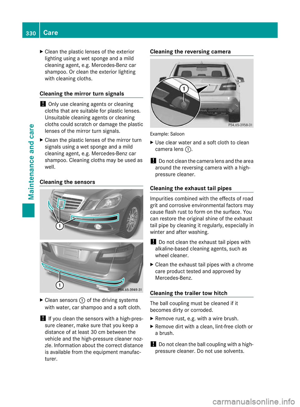
Clean sensors :of the driving systems
with water, car shampoo and a sof tcloth.
! If you clean the sensors with a high-pres-
sure cleaner, make sure that you keep a
distance of at least 30 cm between the
vehicle and the high-pressure cleaner noz-
zle. Information about the correct distance
is available fro mthe equipment manufac-
turer. Cleaning the reversing camera
Example: Saloon
X
Use clear water and a soft cloth to clean
camera lens :.
! Do not clean the camera lens and the area
around the reversing camera with a high-
pressure cleaner.
Cleaning the exhaust tail pipes Impurities combined with the effects of road
grit and corrosive environmental factors may
cause flash rust to form on the surface. You
can restore the original shine of the exhaust
tail pipe by cleaning it regularly, especially in
winter and after washing.
!
Do not clean the exhaust tail pipes with
alkaline-based cleaning agents, such as
wheel cleaner.
X Cleant he exhaust tail pipes with a chrome
care product tested and approved by
Mercedes-Benz.
Cleaning the trailer tow hitch The ball coupling must be cleaned if it
becomes dirty or corroded.
X
Remove rust, e.g. with a wire brush.
X Remove dirt with a clean, lint-free cloth or
a brush.
! Do not clean the ball coupling with a high-
pressure cleaner. Do not use solvents. 330
CareMaintenance and care
Page 352 of 409
G
WARNING
The wheels could work loose if the wheel nuts
and bolts are not tightened to the specified
tightening torque .There is a risk of accident.
Have the tightening torque immediately
checked at a qualified specialist workshop
after a wheel is changed.
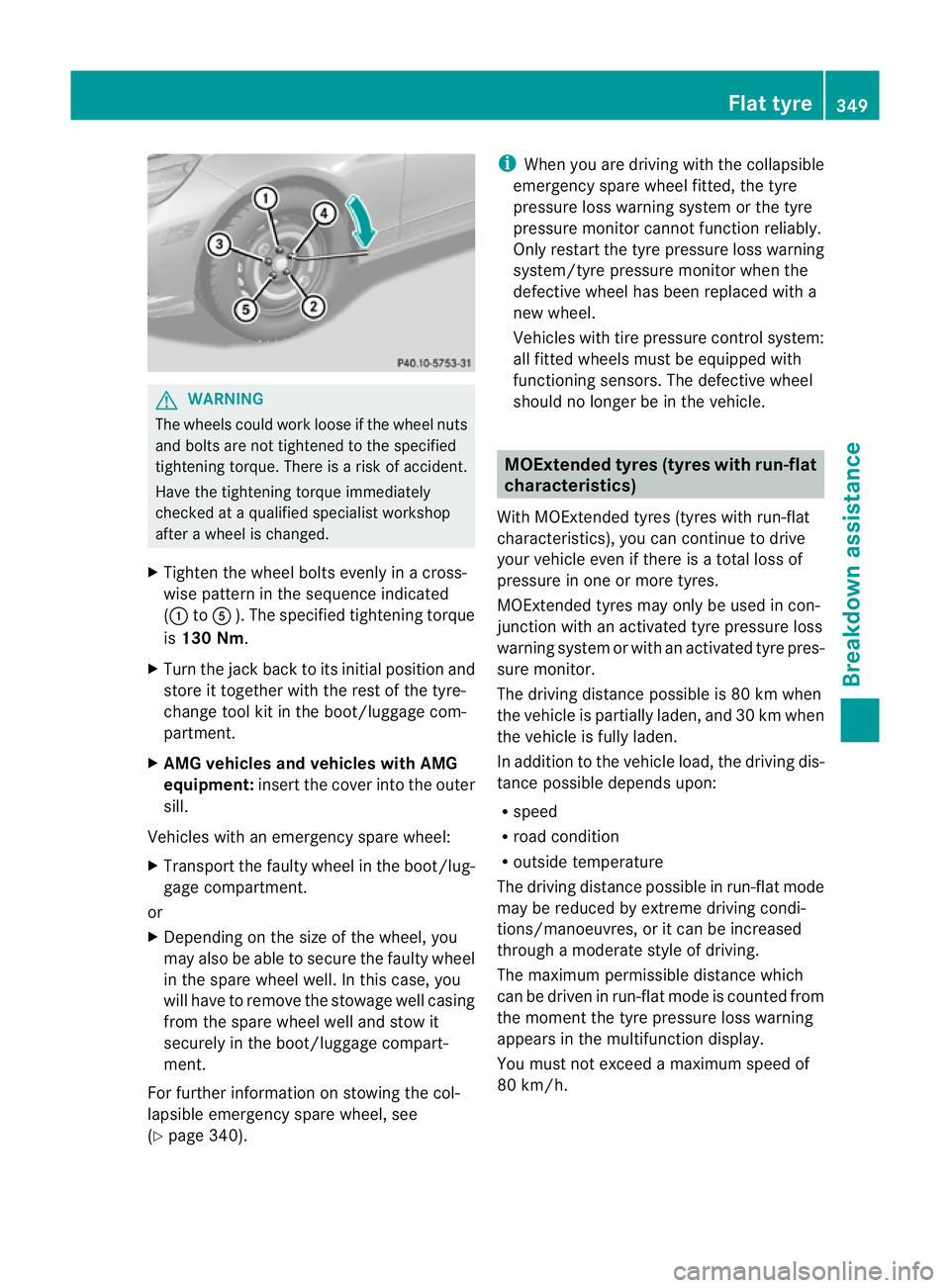
X Tighten the wheel bolts evenly in a cross-
wise pattern in the sequence indicated
(: toA ). The specified tightening torque
is 130 Nm.
X Turn the jack back to its initial position and
store it together with the rest of the tyre-
change tool kit in the boot/luggage com-
partment.
X AMG vehicles and vehicles with AMG
equipment: insert the cover into the outer
sill.
Vehicles with an emergency spare wheel:
X Transport the faulty wheel in the boot/lug-
gage compartment.
or
X Depending on the size of the wheel, you
may also be able to secure the faulty wheel
in the spare wheel well. In this case, you
will have to remove the stowage well casing
from the spare wheel well and stow it
securely in the boot/luggage compart-
ment.
For further information on stowing the col-
lapsible emergency spare wheel, see
(Y page 340). i
When you are driving with the collapsible
emergency spare wheel fitted, the tyre
pressure loss warning system or the tyre
pressure monitor cannot function reliably.
Only restart the tyre pressure loss warning
system/tyre pressure monitor when the
defective wheel has been replaced with a
new wheel.
Vehicles with tire pressure control system:
all fitted wheels must be equipped with
functioning sensors. The defective wheel
should no longer be in the vehicle. MOExtended tyres (tyres with run-flat
characteristics)
With MOExtended tyres (tyres with run-flat
characteristics), you can continue to drive
your vehicle even if there is a total loss of
pressure in one or more tyres.
MOExtended tyres may only be used in con-
junction with an activated tyre pressure loss
warning system or with an activated tyre pres-
sure monitor.
The driving distance possible is 80 km when
the vehicle is partially laden, and 30 km when
the vehicle is fully laden.
In addition to the vehicle load, the driving dis-
tance possible depends upon:
R speed
R road condition
R outside temperature
The driving distance possible in run-flat mode
may be reduced by extreme driving condi-
tions/manoeuvres, or it can be increased
through a moderate style of driving.
The maximum permissible distance which
can be driven in run-flat mode is counted from
the moment the tyre pressure loss warning
appears in the multifunction display.
You must not exceed a maximum speed of
80 km/h. Flat tyre
349Breakdown assistance Z
Page 371 of 409
to ensure tha
tthe tyre pressure in all four
tyres is set correctly for the respective
operating conditions.
The tyre pressure loss warning system can
only give reliable warnings if you have set
the correct tyre pressure. If an incorrect
tyre pressure is set, these incorrectv alues
will be monitored.
X Observe the notes in the section on tyre
pressures ( Ypage 365).
X Make sure that the key is in posi-
tion 2(Ypage 155) in the ignition lock.
X Press the =or; buttononthe steer-
ing wheel to select the Serv. menu.
X Press the 9or: button to select
Tyre pressure .
X Press the abutton.
The Run Flat Indicator active Restart with OK message appears in the
multifunction display.
If you wish to confirm the restart:
X Press the abutton.
The Tyre press. now OK? message
appears in the multifunction display.
X Press the 9or: button to select
Yes .
X Press the abutton.
The Run Flat Indicator restarted message appears in the multifunction dis-
play.
After a teach-in period, the tyre pressure
loss warning system will monitor the set
tyre pressures of all four tyres.
If you wish to cancel the restart:
X Press the %button.
or
X If the Tyre press. now OK? message
appears, press the 9or: button to
select Cancel .
X Press the abutton.
The tyre pressure values stored at the last
restart will continue to be monitored. Tyre pressure monitor
Important safety notes It is the driver's responsibility to set the tyre
inflation to the recommended cold tyre pres-
sure suitable to the operating situation
(Y
page 365). Note that the correct tyre pres-
sure for the current operating situation must
first be taught-in to the tyre pressure monitor.
If there is a substantial loss of pressure, the
warning threshold for the warning message is
aligned to the reference values entered.
Restart the tyre pressure monitor after
adjusting to the cold tyre pressure.
(Y page 369) The current pressures are
saved as new reference values. As a result, a
warning message will appearift he tyre pres-
sure drops significantly.
The tyre pressure monitor does not warn you
of an incorrectly set tyre pressure. Observe
the notes on the recommended tyre pressure
(Y page 365).
The tyre pressure monitor is not able to warn
you of a sudden loss of pressure, e.g. if the
tyre is penetrated by a foreign object. In the
event of a sudden loss of pressure, bring the
vehicle to a halt by braking carefully. Avoid
abrupt steering manoeuvres.
If a tyre pressure monitor system is fitted, the
vehicle's wheels have sensors fitted that
monitor the tyre pressures in all four tyres.
The tyre pressure monitor warns you if the
pressure drops in one or more of the tyres.
The tyre pressure monitor only functions if
the correct sensors are fitted to all wheels.
Information on tyre pressures is displayed in
the multifunction display. After a few minutes
of driving, the current tyre pressure of each
tyre is shown in the multifunction display.
i The tyre pressure values indicated by the
on-board computer may differ from those
measured at a filling station with a pressure
gauge. The tyre pressures shown by the on-
board computer refer to those measured at
sea level. At high altitudes, the tyre pres-
sure values indicated by a pressure gauge 368
Tyre pressureWheels and tyres
Page 372 of 409
are higher than those shown by the on-
board computer. In this case, do no treduce
the tyre pressures.
i The operation of the tyre pressure moni-
tor can be affected by interference from
radio transmitting equipment (e.g. radio
headphones, two-way radios) that may be
being operated in or near the vehicle.
Checking tyre pressure electronically X
Make sure that the key is in posi-
tion 2(Ypage 155) in the ignition lock.
X Press the =or; button on the steer-
ing wheel to select the Serv. menu.
X Press the 9or: button to select
Tyre pressure .
X Press the abutton.
The curren ttyre pressur efor each wheel
will be displayed in the multifunction dis-
play.
If the vehicle has been parked for longer than
20minutes, the Tyre pressures will be displayed after a few minutes of
driving message appears.
After a teach-in period, the tyre pressure
monitor automatically recognises new
wheels or new sensors. As long as a clear
allocation of the tyre pressure values to the
individual wheels is not possible, the Tyrepressure monitor active display mes-
sage is shown instead of the tyre pressure
display .The tyre pressures are already being
monitored.
i If a spare wheel/emergency spare wheel
is fitted, the system may continue to show
the tyre pressure of the wheel that has
been removed for a few minutes. If this
occurs, note that the value displayed for
the position where the spare wheel/emer-
gency spare wheel is fitted is not the same
as the spare wheel/emergency spare
wheel's current tyre pressure. Warning messages of the tyre pressure
monitor If the tyre pressure monitor detects a signifi-
cant pressure loss on one or more tyres, a
warning message is shown in the multifunc-
tion display.
Awarning tone also sounds and
the tyre pressure warning lamp lights up in
the instrument cluster.
Each tyre that is affected by a significant loss
of pressure is highlighted in the pressure dis-
play.
If the Please correct tyre pressure message appears in the multifunction dis-
play:
X
Chec kthe tyre pressure on all four wheels
and correct it if necessary.
i If the wheel positions on the vehicle are
interchanged, the tyre pressures may be
displayed for the wrong positions for a
short time. This is rectified after a few
minutes of driving, and the tyre pressures
are displayed for the correct positions.
Restarting the tyre pressure monitor When you restart the tyre pressure monitor,
all existing warning messages are deleted and
the warning lamps go out. The monitor uses
the currently set tyre pressures as the refer-
ence values for monitoring. In most cases, the
tyre pressure monitor will automatically
detect the new referencev
alues after you
have changed the tyre pressure.
i For an overview of th emenus, see
(Y page 234).
If you wish to define the new reference values
manually:
X Use the table on the inside of the fuel filler
flap to ensure that the tyre pressure is set
correctly in all four tyres for the current
operating conditions. Tyre pressure
369Wheels and tyres Z
Page 382 of 409
Useful information
............................380
Notes on the technical data .............380
Genuine Mercedes-Benz parts .........380
Vehicle electronics ...........................381
Vehicle identification plates ............382
Service products and capacities .....383
Vehicle data ...................................... 392
Boot lid and tailgate opening
dimensions ........................................ 394
Trailer tow hitch ................................ 395
24 GHz radar sensor system (coun-
tryo verview) ..................................... 398 379Technical data
Page 383 of 409
Useful information
i This Owner's Manual describes all models
and all standard and optional equipment
available to your vehicle at the time of pub-
lication of the Owner's Manual. Country-
specific deviations are possible. Please
note that your vehicle may not be equipped
with all features described. This also
applies to safety-relevan tsystems and
functions.
i Please read the information on qualified
specialist workshops (Y page 25).Notes on the technical data
You can find technical data on the Internet at:
http://www.mercedes-benz.com
i The technical data was determined in
accordance with EC Directives. All data
applies to the vehicle's standard equip-
ment. It may therefore differ for vehicles
with optional equipment. You can obtain
further information from a Mercedes-Benz
Service Centre. Genuine Mercedes-Benz parts
Mercedes-Ben ztests genuine parts and con-
version parts and accessories which have
been specifically approved for your vehicle for
their reliability, safety and suitability. Despite
ongoing market research, Mercedes-Benzis
unable to evaluate other parts. Mercedes-
Ben ztherefore accepts no responsibility for
the use of such parts in Mercedes-Ben zvehi-
cles, even if they have been independently or
officially approved.
In Germany and some other countries, certain
parts are only officially approved for installa-
tion or modification if they comply with legal
requirements. All genuine Mercedes-Benz
parts meet this requirement .The use of non- approved parts may invalidate the vehicle's
general operating permit. This is the case if:
R
they cause a change of the vehicle type
from that for which the vehicle's general
operating permit was granted.
R other road users could be endangered.
R the emission or noise levels are adversely
affected. G
WARNING
Driving safety may be impaired if non-
approved parts, tyres and wheels or safety-
relevant accessories are used.
This could lead to malfunctions in safety-rel-
evant systems, e.g. the brake system. This
could cause you to lose control of your vehicle
and cause an accident.
For this reason, Mercedes-Ben zrecommends
that you use genuine Mercedes-Benz parts or
parts of equal quality. Only use tyres, wheels
and accessories that have been specifically
approved for your vehicle.
! Airbags and seat belt tensioners, as well
as control units and sensors for these
restraint systems may be installed in the
following areas of your vehicle:
R doors
R door pillars
R door sills
R seats
R dashboard
R instrument cluster
R centre console
Do not install accessories such as audio
systems in these areas. Do not carry out
repairs or welding. You could impair the
operating efficiency of the restraint sys-
tems.
Have aftermarket accessories installed at
a qualified specialist workshop. Mercedes-
Benz recommends that you use a
Mercedes-Benz Service Centre for this pur-
pose. 380
Genuine Mercedes-Benz partsTechnical data
Page 384 of 409
H
Environmental note
Daimler AG also supplies reconditioned
assemblies and parts which are of the same
quality as new parts. For these, the same war-
ranty applies as for new parts.
Always specify the vehicle identification num-
ber (VIN) (Y page 382) and the engine num-
ber (Y page 383) when ordering genuine
Mercedes-Ben zparts. Vehicle electronics
Tampering with the engine electron-
ics
G
WARNING
Always have work on the engine electronics
and related components carried out at a quali-
fied specialist workshop. Otherwise, the vehi-
cle's operating safety could be affected.
! Only have work carried out on the engine
electronics and its associated parts, such
as control units, sensors and connector
leads, at a qualified specialist workshop.
Vehicle components may otherwise wear
more quickly and the vehicle's operating
permit may be invalidated. Retrofitting of two-way radios and
mobile phones (RF transmitters)
Use the Technical Specification
ISO/TS 21609 41
implementation regulation
when retrofitting RF (radio frequency) trans-
mitters.
If your vehicle has fittings for two-way radio
equipment, use the power supply or aerial
connections intended for use with the basic
wiring. Be sure to observe the manufacturer's
additional instructions when installing. !
Have aftermarket radio frequency trans-
mitting equipmen tinstalled at a qualified
specialist workshop.
The transmission outpu tatthe aerial base
must not exceed the maximum values below. Waveband Maximum
transmission
output (PEAK) Short wave (f < 54 MHz) 100 W
4 m waveband 30 W
2 m waveband 50 W
trunked radio/Tetra 35 W
70 cm waveband 35 W
GSM/DCS/PCS
850/900/1800/1900 10 W
UMTS/LTE 10 W
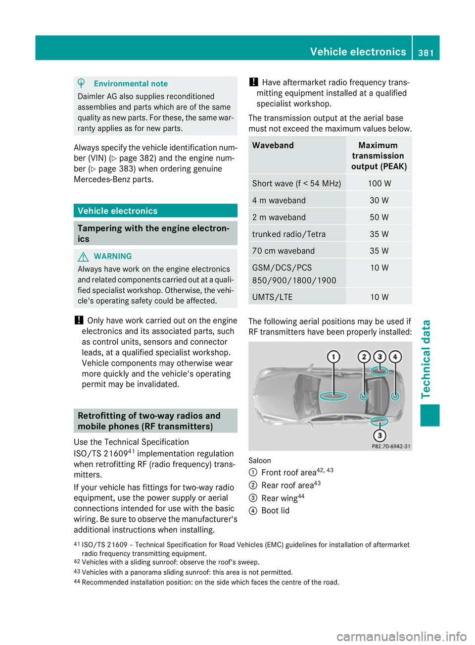
The following aerial positions may be used if
RF transmitters have been properly installed:
Saloon
:
Front roof area 42, 43
; Rear roof area 43
= Rear wing 44
? Boot lid
41 ISO/TS 21609 –Technical Specification for Road Vehicles (EMC) guidelines for installation of aftermarket
radio frequency transmitting equipment.
42 Vehicles with a sliding sunroof: observe the roof's sweep.
43 Vehicles with a panorama sliding sunroof: this area is not permitted.
44 Recommended installation position: on the side which faces the centre of the road. Vehicle electronics
381Technical data Z
Page 394 of 409
!
Only add coolant that has been premixed
with the desired antifreeze protection. You
could otherwise damage the engine.
Further information on coolants can be
found in the Mercedes-Benz Specifications
for Service Products, MB Specifications for
Service Products 310.1, e.g. on the Inter-
net at http://bevo.mercedes-benz.com.
Or contact a qualified specialist workshop.
! Always use a suitable coolant mixture,
even in countries where high temperatures
prevail.
Otherwise, the engine cooling system is not
sufficiently protected from corrosion and
overheating.
! The engine cooling system is filled with
coolant, which must be renewed after
15 years or after 250,000 kilometres at the
latest.
The coolant is a mixture of water and anti-
freeze/corrosion inhibitor. It performs the
following tasks:
R anti-corrosion protection
R antifreeze protection
R raising the boiling point
If antifreeze/corrosion inhibitor is present in
the correct concentration, the boiling point of
the coolant during operation will be around
130 †.
The antifreeze/corrosion inhibitor concentra-
tion in the engine cooling system should:
R be at least 50%. This will protect the engine
cooling system against freezing down to
around -37 †.
R not exceed 55% (antifreeze protection
down to -45 †). Otherwise, heat will not be
dissipated as effectively.
If the vehicle has lost coolant, top it up with
equal amounts of water and antifreeze/cor-
rosion inhibitor. Mercedes-Benz recom-
mends an antifreeze/corrosion inhibitor con-
centrate in accordance with MB Specifica-
tions for Service Products 310.1. The coolant is checked with every mainte-
nance interval at a qualified specialist work-
shop.
i
When the vehicle is first delivered, it is fil-
led with a coolant mixture that ensures
adequate antifreeze and corrosion protec-
tion. Washer fluid
G
WARNING
Windscreen washer fluid/antifreeze is highly
flammable. Avoid spilling windscreen washer
fluid/antifreeze on hot engine components as
it can ignite and burn. Severe burns could be
the result.
! Only use washer fluid that is suitable for
plastic lamp lenses, e.g. MB SummerFit or
MB WinterFit. Unsuitable washer fluid
could damage the plastic lenses of the
headlamps.
! Do not use distilled or de-ionised water in
the washer fluid reservoir. Otherwise, the
level sensor may be damaged.
! Only the washer fluids SummerFit and
WinterFit can be mixed. Otherwise, the
spraying nozzles could become blocked.
At temperatures above freezing:
X Fill the washer fluid reservoir with a mixture
of water and washer fluid, e.g. MB Sum-
merFit.
X Mix 1 part MB SummerFit to 100 parts
water.
At temperatures below freezing:
X Fill the washer fluid reservoir with a mixture
of water and washer fluid, e.g. MB Winter-
Fit. Adapt the mixing ratio to the outside
temperatures.
X Down to Ò10 †: mix 1 part MB WinterFit to
2 parts water. Service products and capacities
391Technical data Z
Page 401 of 409
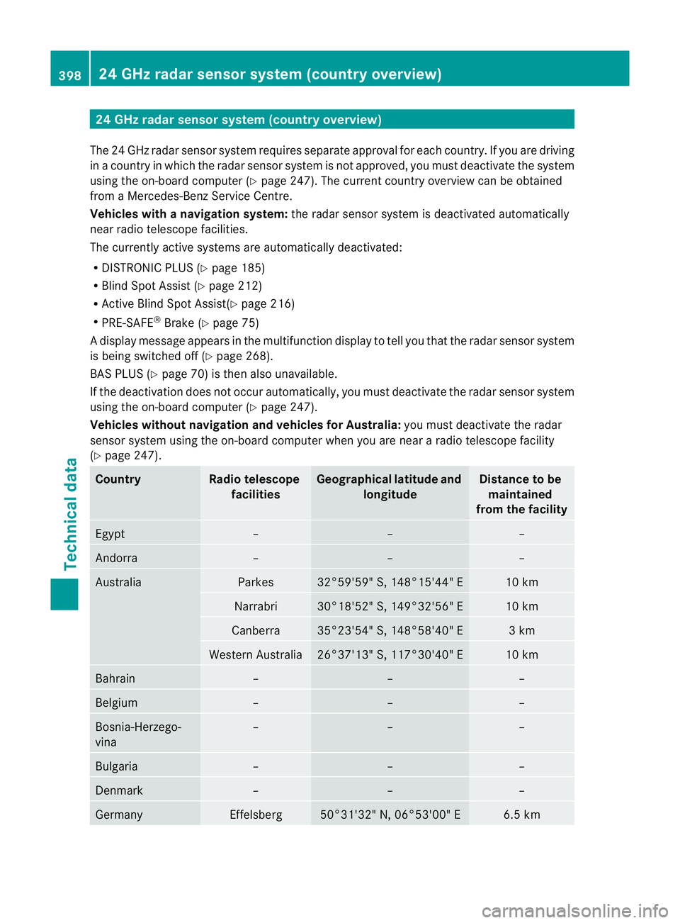
24 GHz radar sensor system (country overview)
The 24 GHz radar senso rsystem requires separat eapproval for each country. If you are driving
in a country in which the radar senso rsystem is no tapproved, you must deactivate the system
using the on-board computer (Y page 247). The current country overview can be obtained
from a Mercedes-Benz Service Centre.
Vehicles with anavigation system: the radar sensor system is deactivated automatically
near radio telescope facilities.
The currently active systems are automatically deactivated:
R DISTRONIC PLUS (Y page 185)
R Blind Spot Assist (Y page 212)
R Active Blind Spot Assist(Y page 216)
R PRE-SAFE ®
Brake (Y page 75)
Ad isplay message appears in the multifunction display to tell you that the radar sensor system
is being switched off (Y page 268).
BAS PLUS (Y page 70) is the nalso unavailable.
If the deactivation does not occur automatically, you must deactivate the radar sensor system
using the on-board computer (Y page 247).
Vehicles withou tnavigation and vehicles for Australia: you must deactivate the radar
sensor system using the on-board computer whe nyou are near a radio telescope facility
(Y page 247). Country Radio telescope
facilities Geographical latitude and
longitude Distance to be
maintained
from the facility Egypt – – –
Andorra – – –
Australia Parkes 32°59'59" S, 148°15'44" E 10 km
Narrabri 30°18'52" S, 149°32'56" E 10 km
Canberra 35°23'54" S, 148°58'40" E 3 km
Western Australia 26°37'13" S, 117°30'40" E 10 km
Bahrain – – –
Belgium – – –
Bosnia-Herzego-
vina – – –
Bulgaria – – –
Denmark – – –
Germany Effelsberg 50°31'32" N, 06°53'00" E 6.5 km398
24 GHz radar sensor system (country overview)Technical data
Page 402 of 409
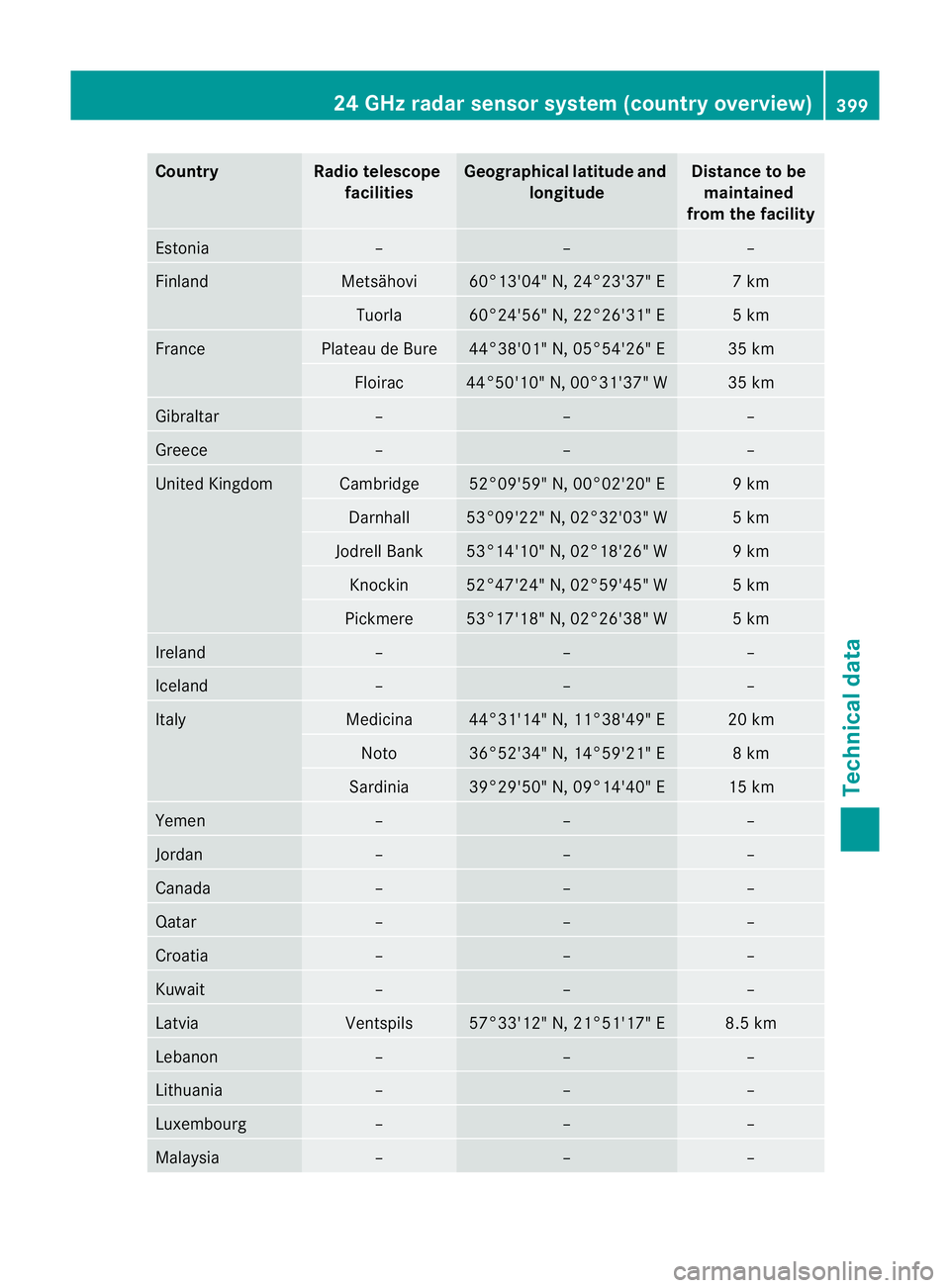
Country Radio telescope
facilities Geographica
llatitude and
longitude Distance to be
maintained
from the facility Estonia – – –
Finland Metsähovi 60°13'04" N, 24°23'37" E 7 km
Tuorla 60°24'56" N, 22°26'31" E 5 km
France Plateau de Bure 44°38'01" N, 05°54'26" E 35 km
Floirac 44°50'10" N, 00°31'37" W 35 km
Gibraltar – – –
Greece – – –
United Kingdom Cambridge 52°09'59" N, 00°02'20" E 9 km
Darnhall 53°09'22" N, 02°32'03" W 5 km
Jodrell Bank 53°14'10" N, 02°18'26" W 9 km
Knockin 52°47'24" N, 02°59'45" W 5 km
Pickmere 53°17'18" N, 02°26'38" W 5 km
Ireland – – –
Iceland – – –
Italy Medicina 44°31'14" N, 11°38'49" E 20 km
Noto 36°52'34" N, 14°59'21" E 8 km
Sardinia 39°29'50" N, 09°14'40" E 15 km
Yemen – – –
Jordan – – –
Canada – – –
Qatar – – –
Croatia – – –
Kuwait – – –
Latvia Ventspils 57°33'12" N, 21°51'17" E 8.5 km
Lebanon – – –
Lithuania – – –
Luxembourg – – –
Malaysia – – –24 GHz radar sensor system (country overview)
399Technical data Z