Control MERCEDES-BENZ E-Class SEDAN 2016 W213 Owners Manual
[x] Cancel search | Manufacturer: MERCEDES-BENZ, Model Year: 2016, Model line: E-Class SEDAN, Model: MERCEDES-BENZ E-Class SEDAN 2016 W213Pages: 350, PDF Size: 6.71 MB
Page 258 of 350
You receive information about operating your
vehicle, about the nearest authorized
Mercedes-Benz Center and about other prod-
ucts and services from Mercedes-Benz.
You can find further information on the
mbrace system under "Owners Online" at
http://www.mbusa.com.
The system has not been able to initiate an
MB Info call, if:
Rthe indicator lamp in MB Info call button
ïis flashing continuously.
Rno voice connection to the Mercedes-Benz
Customer Assistance Center was estab-
lished.
This can occur if the relevant mobile phone
network is not available, for example.
The Call Failed
message appears in the
multifunction display.
XTo end a call: press the~button on the
multifunction steering wheel.
or
XPress the corresponding COMAND/Audio
20 button for ending a phone call.
Call priority
When service calls are active, e.g. Roadside
Assistance or MB Info calls, an emergency
call can still be initiated. In this case, an emer-
gency call will take priority and override all
other active calls.
The indicator lamp of the respective button
flashes until the call is ended.
An emergency call can only be terminated by the Mercedes-Benz Customer Assistance
Center.
All other calls can be ended by pressing:
Rthe ~ button on the multifunction steer-
ing wheel
Rthe corresponding button in COMAND/
Audio 20 to end the voice call
When a call is initiated, the audio system is
muted. The mobile phone is no longer connected to
COMAND/Audio 20.
However, if you want to use your mobile
phone, do so only when the vehicle is station-
ary and in a safe location.
Garage door opener
General notes
The HomeLink®garage door opener integra-
ted in the rear-view mirror allows you to oper-
ate up to three different door and gate sys-
tems.
Use the integrated garage door opener only
on garage doors that:
Rhave safety stop and reverse features and
Rmeet current U.S. federal safety standards
Once programed, the integrated garage door
opener in the rear-view mirror will assume the
function of the garage door system's remote
control. Please also read the operating
instructions for the garage door system.
When programming a garage door opener,
park the vehicle outside the garage. Do not
run the engine while programming.
Certain garage door drives are incompatible
with the integrated garage door opener. If you
have difficulty programing the integrated
garage door opener, contact an authorized
Mercedes-Benz Center.
Alternatively, you can call the following tele-
phone assistance services:
RUSA: Mercedes-Benz Customer Assistance
Center at 1-800-FOR-MERCedes
RCanada: Customer Service at
1-800-387-0100
RHomeLink®hotline 1-800-355-3515 (free
of charge)
More information on HomeLink
®and/or
compatible products is also available online
at http://www.homelink.com.
Notes on the declaration of conformity
(
Ypage 31).
256Features
Stowage and features
Page 259 of 350
USA: FCC ID: CB2HMIHL4
Canada: IC: 279B-HMIHL4
Important safety notes
GWARNING
When you operate or program the garage door
with the integrated garage door opener, per-
sons in the range of movement of the garage
door can become trapped or struck by the
garage door. There is a risk of injury.
When using the integrated garage door
opener, always make sure that nobody is
within the range of movement of the garage
door.
GWARNING
Combustion engines emit poisonous exhaust
gases such as carbon monoxide. Inhaling
these exhaust gases leads to poisoning. There
is a risk of fatal injury. Therefore never leave
the engine running in enclosed spaces with-
out sufficient ventilation.
Programming
Programming buttons
Pay attention to the "Important safety notes"
(
Ypage 257).
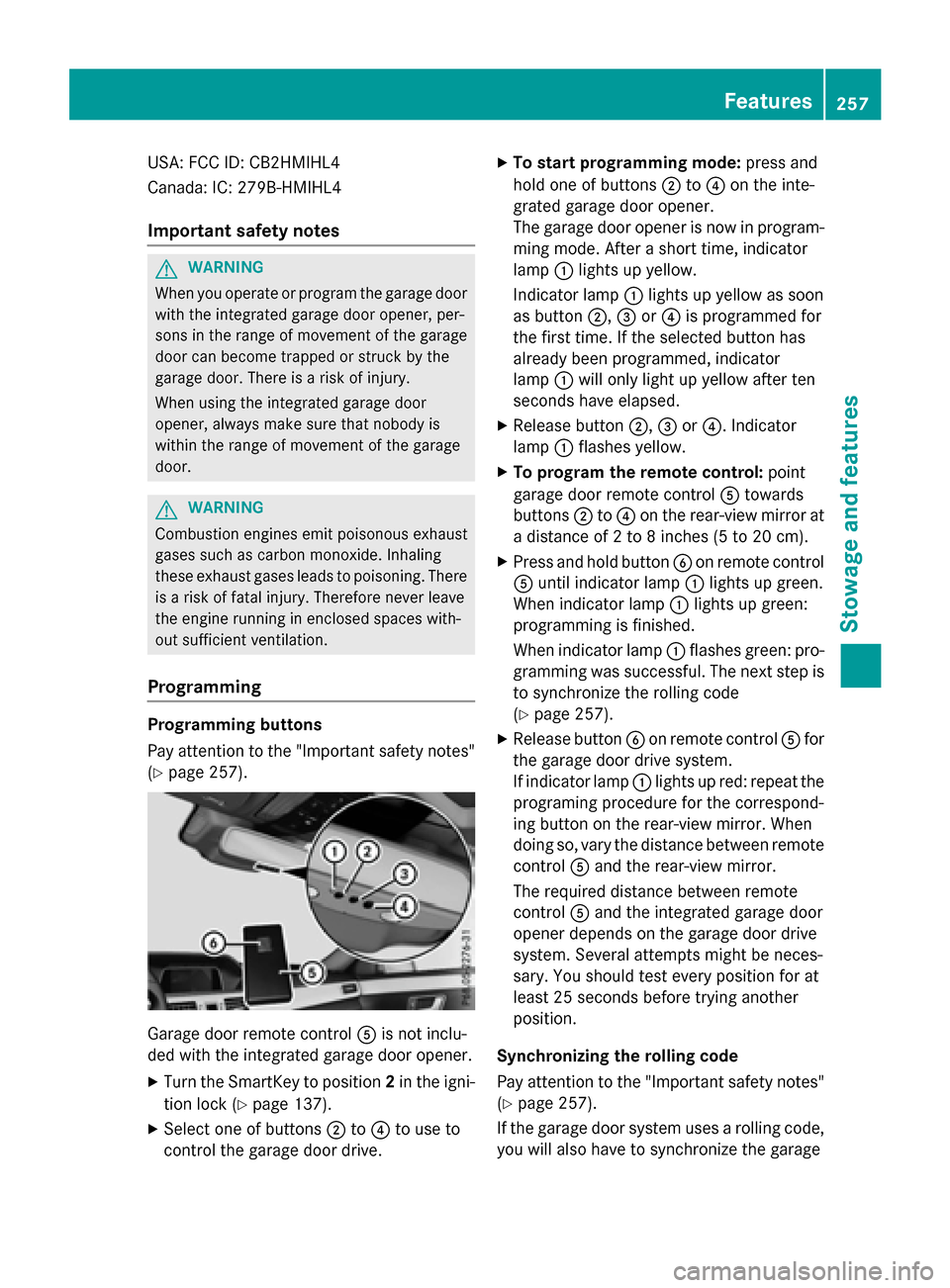
Garage door remote control Ais not inclu-
ded with the integrated garage door opener.
XTurn the SmartKey to position 2in the igni-
tion lock (
Ypage 137).
XSelect one of buttons ;to? to use to
control the garage door drive.
XTo start programming mode: press and
hold one of buttons ;to? on the inte-
grated garage door opener.
The garage door opener is now in program-
ming mode. After a short time, indicator
lamp :lights up yellow.
Indicator lamp :lights up yellow as soon
as button ;,=or? is programmed for
the first time. If the selected button has
already been programmed, indicator
lamp :will only light up yellow after ten
seconds have elapsed.
XRelease button ;,=or?. Indicator
lamp :flashes yellow.
XTo program the remote control: point
garage door remote control Atowards
buttons ;to? on the rear-view mirror at
a distance of 2 to 8 inches (5 to 20 cm).
XPress and hold button Bon remote control
A until indicator lamp :lights up green.
When indicator lamp :lights up green:
programming is finished.
When indicator lamp :flashes green: pro-
gramming was successful. The next step is
to synchronize the rolling code
(
Ypage 257).
XRelease button Bon remote control Afor
the garage door drive system.
If indicator lamp :lights up red: repeat the
programing procedure for the correspond-
ing button on the rear-view mirror. When
doing so, vary the distance between remote
control Aand the rear-view mirror.
The required distance between remote
control Aand the integrated garage door
opener depends on the garage door drive
system. Several attempts might be neces-
sary. You should test every position for at
least 25 seconds before trying another
position.
Synchronizing the rolling code
Pay attention to the "Important safety notes"
(
Ypage 257).
If the garage door system uses a rolling code,
you will also have to synchronize the garage
Features257
Stowage and features
Z
Page 260 of 350
door system with the integrated garage door
opener in the rear-view mirror. To do this you
will need to use the programming button on
the door drive control panel. The program-
ming button may be positioned in different
places depending on the manufacturer. It is
usually located on the door drive unit on the
garage ceiling.
Familiarize yourself with the garage door
drive operating instructions, e.g. under "Pro-
gramming of additional remote controls",
before carrying out the following steps.
Your vehicle must be within reach of the
garage door or gate opener drive. Make sure
that neither your vehicle nor any persons/
objects are present within the sweep of the
door or gate.
XTurn the SmartKey to position2in the igni-
tion lock (
Ypage 137).
XGet out of the vehicle.
XPress the programming button on the door drive unit.
Usually, you now have 30 seconds to ini-
tiate the next step.
XGet into the vehicle.
XPress previously programmed button ;,
= or? on the integrated garage door
opener until the door closes.
The rolling code synchronization is then
complete.
Notes on programming the remote con-
trol
Canadian radio frequency laws require a
"break" (or interruption) of the transmission
signals after broadcasting for a few seconds. Therefore, these signals may not last long
enough for the integrated garage door
opener. The signal is not recognized during
programming. Comparable with Canadian
law, some U.S. garage door openers also fea-
ture a "break". Proceed as follows:
Rif you live in Canada
Rif you have difficulties programming the
garage door opener (regardless of where
you live) when using the programming
steps.
XPress and hold one of buttons
;to? on
the integrated garage door opener.
After a short time, indicator lamp :lights
up yellow.
XRelease the button.
Indicator lamp :flashes yellow.
XPress button Bof garage door remote
control Afor two seconds, then release it
for t
wo seconds.
XPress button Bagain for two seconds.
XRepeat this sequence on button Bof
remote control Auntil indicator lamp :
lights up green.
When indicator lamp :lights up green:
programming is finished.
When indicator lamp :flashes green: pro-
gramming was successful. The next step is
to synchronize the rolling code.
XRelease button Bof remote control Aof
the garage door drive.
If indicator lamp :lights up red: repeat the
programming process for the correspond-
ing button on the rear-view mirror. When
doing so, vary the distance between remote
control Aand the rear-view mirror.
The required distance between remote
control Aand the integrated garage door
opener depends on the garage door drive
system. Several attempts might be neces-
sary. You should test every position for at
least 25 seconds before trying another
position.
258Features
Stowage and features
Page 261 of 350
Problems when programming
If you are experiencing problems programing
the integrated garage door opener on the
rear-view mirror, take note of the following
instructions:
RCheck the transmitter frequency used by
garage door drive remote controlAand
whether it is supported. The transmitter
frequency can usually be found on the back
of the garage door drive remote control.
The integrated garage door opener is com-
patible with devices that have units which
operate in the frequency range of 280 to
433 MHz.
RReplace the batteries in garage door
remote control A. This increases the like-
lihood that garage door remote control A
will transmit a strong and precise signal to
the integrated garage door opener.
RWhen programming, hold remote control
A at varying distances and angles from the
button which you are programming. Try var-
ious angles at a distance between 2and
12 inches (5to 30 cm) or at the same angle
but at varying distances.
RIf another remote control is available for the
same garage door drive, repeat the same
programming steps with this remote con-
trol. Before performing these steps, make
sure that new batteries have been installed
in garage door drive remote control A.
RNote that some remote controls only trans-
mit for a limited amount of time (the indi-
cator lamp on the remote control goes out).
Press buttonBon remote control Aagain
before transmission ends.
RAlign the antenna cable of the garage door
opener unit. This can improve signal recep-
tion/transmission.
Opening/closing the garage door
After it has been programmed, the integrated
garage door opener performs the function of
the garage door system remote control. Please also read the operating instructions
for the garage door system.
XTurn the SmartKey to position
2in the igni-
tion lock (
Ypage 137).
XPress button ;,=or? which you have
programmed to operate the garage door.
Garage door system with a fixed code: indi-
cator lamp :lights up green.
Garage door system with a rolling code:
indicator lamp :flashes green.
The transmitter will transmit a signal as
long as the button is pressed. The trans-
mission is halted after a maximum of ten
seconds and indicator lamp :lights up
yellow.
XPress button ;,=or? again if neces-
sary.
Clearing the memory
Make sure that you clear the memory of the
integrated garage door opener before selling
the vehicle.
XTurn the SmartKey to position 2in the igni-
tion lock (
Ypage 137).
XPress and hold buttons ;and ?.
The indicator lamp initially lights up yellow
and then green.
XRelease buttons ;and ?.
The memory of the integrated garage door
opener in the rear-view mirror is cleared.
Floormats
GWARNING
Objects in the driver's footwell can restrict the pedal travel or obstruct a depressed pedal.
The operating and road safety of the vehicle is
jeopardized. There is a risk of an accident.
Make sure that all objects in the vehicle are
stowed correctly, and that they cannot enter
the driver's footwell. Install the floormats
securely and as specified in order to ensure
sufficient clearance for the pedals. Do not use
Features259
Stowage and features
Z
Page 278 of 350
GWARNING
Work carried out incorrectly on the battery
can lead, for example, to a short circuit and
thus damage the vehicle electronics. This can
lead to function restrictions applying to
safety-relevant systems, e.g the lighting sys-
tem, the ABS (anti-lock braking system) or the
ESP
®(Electronic Stability Program). The oper-
ating safety of your vehicle may be restricted.
You could lose control of the vehicle, for
example:
Rwhen braking
Rin the event of abrupt steering maneuvers
and/or when the vehicle's speed is not
adapted to the road conditions
There is a risk of an accident.
In the event of a short circuit or a similar inci-
dent, contact a qualified specialist workshop
immediately. Do not drive any further. You
should have all work involving the battery car- ried out at a qualified specialist workshop.
For further information about ABS and ESP®,
see (
Ypage 75) and (Ypage 80).
GWARNING
Electrostatic build-up can lead to the creation of sparks, which could ignite the highly explo-
sive gases of a battery. There is a risk of an
explosion.
Before handling the battery, touch the vehicle
body to remove any existing electrostatic
build-up.
The highly flammable gas mixture forms when
charging the battery as well as when jump-
starting.
Always make sure that neither you nor the
battery is electrostatically charged. A build-
up of electrostatic charge can be caused, for
example:
Rby wearing clothing made from synthetic
fibers
Rdue to friction between clothing and seats
Rif you push or pull the battery across the
carpet or other synthetic materials
Rif you wipe the battery with a cloth
GWARNING
During the charging process, a battery produ-
ces hydrogen gas. If a short circuit occurs or
sparks are created, the hydrogen gas can
ignite. There is a risk of an explosion.
RMake sure that the positive terminal of a
connected battery does not come into con- tact with vehicle parts.
RNever place metal objects or tools on a bat-
tery.
RIt is important that you observe the descri-
bed order of the battery terminals when
connecting and disconnecting a battery.
RWhen jump-starting, make sure that the
battery poles with identical polarity are
connected.
RIt is particularly important to observe the
described order when connecting and dis-
connecting the jumper cables.
RNever connect or disconnect the battery
terminals while the engine is running.
GWARNING
Battery acid is caustic. There is a risk of injury.
Avoid contact with skin, eyes or clothing. Do
not inhale any battery gases. Do not lean over
the battery. Keep children away from batter-
ies. Wash away battery acid immediately with
plenty of clean water and seek medical atten-
tion.
HEnvironmental note
Batteries contain dangerous
substances. It is against the
law to dispose of them with
the household rubbish. They
must be collected separately and recycled to protect the
environment.
Dispose of batteries in an
environmentally friendly
manner. Take discharged
276Battery (vehicle)
Roadside Assistance
Page 291 of 350
other obstacles. If it is necessary to drive over
curbs, speed humps or similar elevations, try
to do so slowly and at an obtuse angle. Oth-
erwise, the tires, particularly the sidewalls,
may be damaged.
Regular checking of wheels and tires
GWARNING
Damaged tires can cause tire inflation pres-
sure loss. As a result, you could lose control of
your vehicle. There is a risk of accident.
Check the tires regularly for signs of damage
and replace any damaged tires immediately.
Regularly check the wheels and tires of your
vehicle for damage at least once a month, as
well as after driving off-road or on rough
roads. Damaged wheels can cause a loss of
tire pressure. Pay particular attention to dam-
age such as:
Rcuts in the tires
Rpunctures
Rtears in the tires
Rbulges on tires
Rdeformation or severe corrosion on wheels
Regularly check the tire tread depth and the
condition of the tread across the whole width
of the tire (
Ypage 289). If necessary, turn the
front wheels to full lock in order to inspect the
inner side of the tire surface.
All wheels must have a valve cap to protect
the valve against dirt and moisture. Do not
mount anything onto the valve other than the
standard valve cap or other valve caps
approved by Mercedes-Benz for your vehicle.
Do not use any other valve caps or systems,
e.g. tire pressure monitoring systems.
Regularly check the pressure of all the tires
particularly prior to long trips. Adjust the tire
pressure as necessary (
Ypage 291).
Observe the notes on the emergency spare
wheel (
Ypage 329). The service life of tires depends, among other
things, on the following factors:
RDriving style
RTire pressure
RDistance covered
Notes on tire tread
GWARNING
Insufficient tire tread will reduce tire traction.
The tire is no longer able to dissipate water.
This means that on wet road surfaces, the risk
of hydroplaning increases, in particular where speed is not adapted to suit the driving con-
ditions. There is a risk of accident.
If the tire pressure is too high or too low, tires
may exhibit different levels of wear at differ-
ent locations on the tire tread. Thus, you
should regularly check the tread depth and
the condition of the tread across the entire
width of all tires.
Minimum tire tread depth for:
RSummer tires: âin (3 mm)
RM+S tires: ãin (4 mm)
For safety reasons, replace the tires before
the legally prescribed limit for the minimum
tire tread depth is reached.
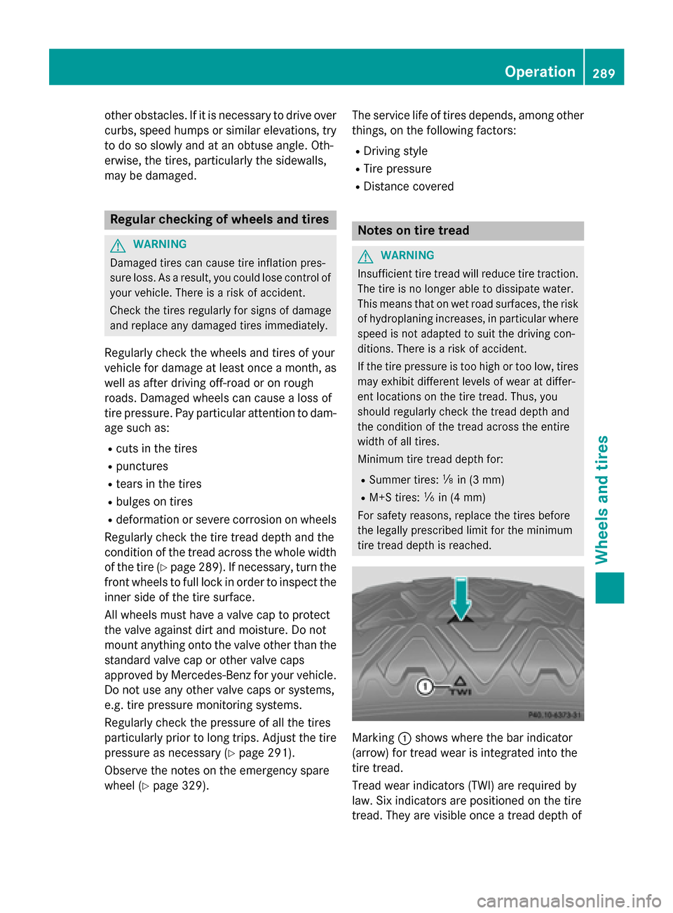
Marking :shows where the bar indicator
(arrow) for tread wear is integrated into the
tire tread.
Tread wear indicators (TWI) are required by
law. Six indicators are positioned on the tire
tread. They are visible once a tread depth of
Operation289
Wheels and tires
Z
Page 292 of 350
approximatelyáin(1.6 mm )ha sbeen
re ached. If this is the case, the tire is so worn
that it must be replaced.
Selecting, mounting and replacing
tires
ROnly mount tires and wheels of the same
type and make.
Exception: it is permissible to install a dif-
ferent type or make in the event of a flat
tire. Observe the "MOExtended tires (tires
with run-flat characteristics" section
(
Ypage 272).
ROnly mount tires of the correct size onto
the wheels.
RBreak in new tires at moderate speeds for
the first 60 miles (100 km). They only reach
their full performance after this distance.
RDo not drive with tires which have too little
tread depth, as this significantly reduces
the traction on wet roads (hydroplaning).
RReplace the tires after six years at the lat-
est, regardless of wear.
Observe the notes on the emergency spare
wheel (
Ypage 329).
MOExtended tires (tires with run-flat
properties)
With MOExtended tires (tires with run flat
characteristics), you can continue to drive
your vehicle even if there is a total loss of
pressure in one or more tires.
MOExtended tires may only be used in con-
junction with an active tire pressure monitor
and only on wheels specifically tested by
Mercedes-Benz.
Notes on driving with MOExtended tires with
a flat tire (
Ypage 272).
Vehicles equipped with MOExtended tires are
not equipped with a TIREFIT kit at the factory.
It is therefore recommended that you addi-
tionally equip your vehicle with a TIREFIT kit if you mount tires that do not feature run-flat properties, e.g. winter tires. A TIREFIT kit can
be obtained from a qualified specialist work-
shop.
Winter operation
General notes
You can find information about this in the
Digital Operator's Manual.
Driving with summer tires
At temperatures below 45
‡(+7 †), summer
tires lose elasticity and therefore traction and
braking power. Change the tires on your vehi-
cle to M+S tires. Using summer tires at very
cold temperatures could cause cracks to
form, thereby damaging the tires perma-
nently. Mercedes-Benz cannot accept
responsibility for this type of damage.
GWARNING
Damaged tires can cause tire inflation pres-
sure loss. As a result, you could lose control of
your vehicle. There is a risk of accident.
Check the tires regularly for signs of damage
and replace any damaged tires immediately.
M+S tires
GWARNING
M+S tires with a tire tread depth of less than
ã in (4 mm) are not suitable for use in winter
and do not provide sufficient traction. There is
a risk of an accident.
M+S tires with a tread depth of less than ãin
(4 mm) must be replaced immediately.
Further information can be found in the Digi-
tal Operator's Manual.
290Winter operation
Wheels and tires
Page 304 of 350
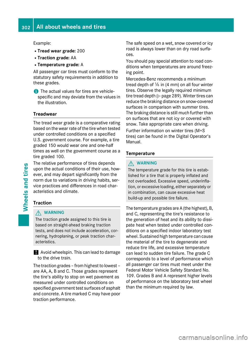
Example:
RTread wear grade:200
RTraction grade:AA
RTemperature grade: A
All passenger car tires must conform to the
statutory safety requirements in addition to
these grades.
iThe actual values for tires are vehicle-
specific and may deviate from the values in
the illustration.
Treadwear
The tread wear grade is a comparative rating
based on the wear rate of the tire when tested
under controlled conditions on a specified
U.S. government course. For example, a tire
graded 150 would wear one and one-half
times as well on the government course as a
tire graded 100.
The relative performance of tires depends
upon the actual conditions of their use, how-
ever, and may depart significantly from the
norm due to variations in driving habits, ser-
vice practices and differences in road char-
acteristics and climate.
Traction
GWARNING
The traction grade assigned to this tire is
based on straight-ahead braking traction
tests, and does not include acceleration, cor-
nering, hydroplaning, or peak traction char-
acteristics.
!Avoid wheelspin. This can lead to damage
to the drive train.
The traction grades – from highest to lowest –
are AA, A, B and C. Those grades represent
the tire's ability to stop on wet pavement as
measured under controlled conditions on
specified government test surfaces of asphalt
and concrete. A tire marked C may have poor
traction performance. The safe speed on a wet, snow covered or icy
road is always lower than on dry road surfa-
ces.
You should pay special attention to road con-
ditions when temperatures are around freez-
ing point.
Mercedes-Benz recommends a minimum
tread depth of
ãin (4 mm) on all four winter
tires. Observe the legally required minimum
tire tread depth (
Ypage 289). Winter tires can
reduce the braking distance on snow-covered
surfaces in comparison with summer tires.
The braking distance is still much further than
on surfaces that are not icy or covered with
snow. Take appropri ate ca
re when driving.
Further information on winter tires (M+S
tires) can be found in the Digital Operator's
Manual.
Temperature
GWARNING
The temperature grade for this tire is estab-
lished for a tire that is properly inflated and
not overloaded. Excessive speed, underinfla-
tion, or excessive loading, either separately or
in combination, can cause excessive heat
build-up and possible tire failure.
The temperature grades are A (the highest), B,
and C, representing the tire's resistance to
the generation of heat and its ability to dissi-
pate heat when tested under controlled con-
ditions on a specified indoor laboratory test
wheel. Sustained high temperature can cause
the material of the tire to degenerate and
reduce tire life, and excessive temperature
can lead to sudden tire failure. The grade C
corresponds to a level of performance which
all passenger car tires must meet under the
Federal Motor Vehicle Safety Standard No.
109. Grades B and A represent higher levels
of performance on the laboratory test wheel
than the minimum required by law.
302All about wheels an d tires
Wheels and tires
Page 310 of 350
Curb weight
The weight of a vehicle with standard equip-
ment including the maximum capacity of fuel,
oil and coolant. It also includes the air-condi-
tioning system and optional equipment if
these are installed in the vehicle, but does not
include passengers or luggage.
Maximum load rating
The maximum load rating is the maximum
permissible weight in kilograms or lbs for
which a tire is approved.
Maximum permissible tire pressure
Maximum permissible tire pressure for one
tire.
Maximum load on one tire
Maximum load on one tire. This is calculated
by dividing the maximum axle load of one axle
by two.
PSI (pounds per square inch)
A standard unit of measure for tire pressure.
Aspect ratio
Relationship between tire height and tire
width in percent.
Tire pressure
Pressure inside the tire applying an outward
force to every square inch of the tire's sur-
face. The tire pressure is specified in pounds
per square inch (psi), in kilopascal (kPa) or in
bar. The tire pressure should only be correc-
ted when the tires are cold.
Cold tire pressure
The tires are cold:
Rif the vehicle has been parked without
direct sunlight on the tires for at least three
hours and
Rif the vehicle has not been driven further
than 1 mile (1.6 km) Tread
The part of the tire that comes into contact
with the road.
Bead
The tire bead ensures that the tire
sits
securely on t
he wheel. There are several steel
wires in the bead to prevent the tire from
coming loose from the wheel rim.
Sidewall
The part of the tire between the tread and the bead.
Weight of optional extras
The combined weight of those optional extras
that weigh more than the replaced standard
parts and more than 2.3 kg (5 lbs). These
optional extras, such as high-performance
brakes, level control, a roof rack or a high-
performance battery, are not included in the
curb weight and the weight of the accesso-
ries.
TIN (Tire Identification Number)
This is a unique identifier which can be used
by a tire manufacturer to identify tires, for
example for a product recall, and thus identify
the purchasers. The TIN is made up of the
manufacturer's identity code, tire size, tire
type code and the manufacturing date.
Load bearing index
The load bearing index (also load index) is a
code that contains the maximum load bearing
capacity of a tire.
Traction
Traction is the result of friction between the
tires and the road surface.
Tread wear indicators
Narrow bars (tread wear bars) that are dis-
tributed over the tire tread. If the tire tread is
level with the bars, the wear limit of áin
(1.6 mm) has been reached.
308All about wheels and tires
Wheels and tires
Page 316 of 350
XTurn the crank of the jack counter-clock-
wise until the vehicle is once again standing
firmly on the ground.
XPlace the jack to one side.
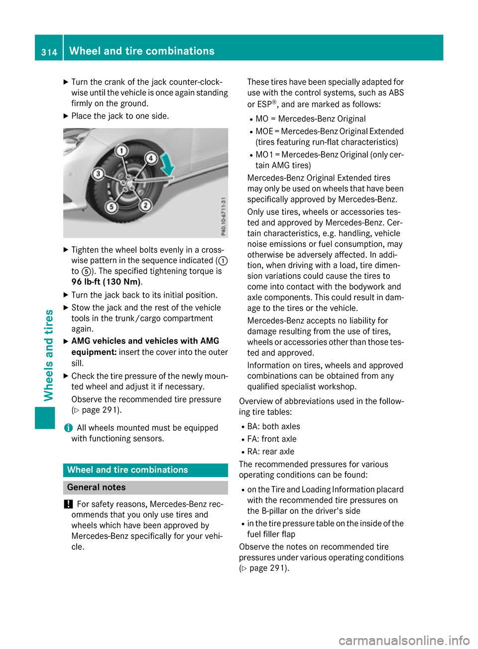
XTighten the wheel bolts evenly in a cross-
wise pattern in the sequence indicated (:
to A). The specified tightening torque is
96 lb-ft (130 Nm).
XTurn the jack back to its initial position.
XStow the jack and the rest of the vehicle
tools in the trunk/cargo compartment
again.
XAMG vehicles and vehicles with AMG
equipment: insert the cover into the outer
sill.
XCheck the tire pressure of the newly moun-
ted wheel and adjust it if necessary.
Observe the recommended tire pressure
(
Ypage 291).
iAll wheels mounted must be equipped
with functioning sensors.
Wheel and tire combinations
General notes
!
For safety reasons, Mercedes-Benz rec-
ommends that you only use tires and
wheels which have been approved by
Mercedes-Benz specifically for your vehi-
cle. These tires have been specially adapted for
use with the control systems, such as ABS
or ESP
®, and are marked as follows:
RMO = Mercedes-Benz Original
RMOE = Mercedes-Benz Original Extended
(tires featuring run-flat characteristics)
RMO1 = Mercedes-Benz Original (only cer-
tain AMG tires)
Mercedes-Benz Original Extended tires
may only be used on wheels that have been
specifically approved by Mercedes-Benz.
Only use tires, wheels or accessories tes-
ted and approved by Mercedes-Benz. Cer-
tain characteristics, e.g. handling, vehicle
noise emissions or fuel consumption, may
otherwise be adversely affected. In addi-
tion, when driving with a load, tire dimen-
sion variations could cause the tires to
come into contact with the bodywork and
axle components. This could result in dam-
age to the tires or the vehicle.
Mercedes-Benz accepts no liability for
damage resulting from the use of tires,
wheels or accessories other than those tes-
ted and approved.
Information on tires, wheels and approved
combinations can be obtained from any
qualified specialist workshop.
Overview of abbreviations used in the follow-
ing tire tables:
RBA: both axles
RFA: front axle
RRA: rear axle
The recommended pressures for various
operating conditions can be found:
Ron the Tire and Loading Information placard with the recommended tire pressures on
the B-pillar on the driver's side
Rin the tire pressure table on the inside of the
fuel filler flap
Observe the notes on recommended tire
pressures under various operating conditions
(
Ypage 291).
314Wheel and tire combinations
Wheels and tires