ECU MERCEDES-BENZ E WAGON 2002 S210 Owner's Guide
[x] Cancel search | Manufacturer: MERCEDES-BENZ, Model Year: 2002, Model line: E WAGON, Model: MERCEDES-BENZ E WAGON 2002 S210Pages: 354, PDF Size: 15.95 MB
Page 270 of 354
267 Fuses
Te ch n i c a l
data Instruments
and controlsOperation DrivingInstrument
cluster displayPractical hintsCar care Index Fuses
Before replacing a blown fuse, determine the cause of
the short circuit.
Spare fuses are supplied inside the main fuse box.
Observe amperage and color of fuse.
A special fuse puller is supplied with the vehicle tools.
Always use a new fuse for replacement. Never attempt to
repair or bridge a blown fuse.
A fuse chart can be found inside the corresponding fuse
box cover.
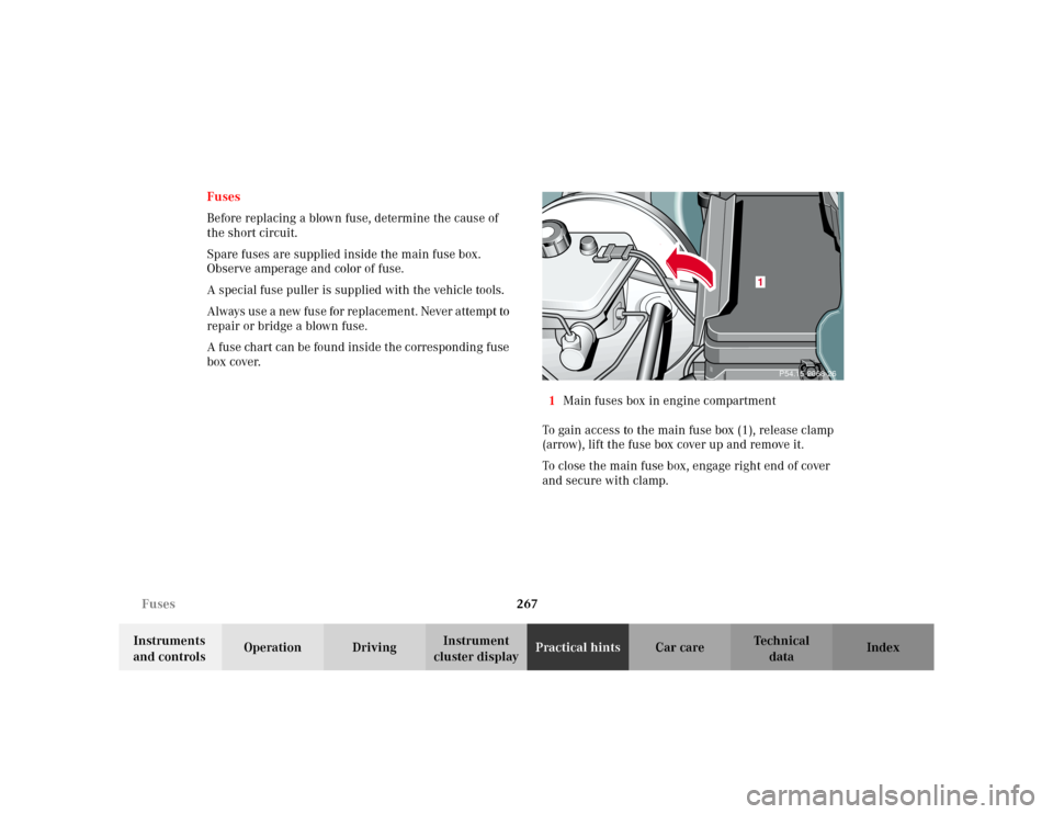
1Main fuses box in engine compartment
To gain access to the main fuse box (1), release clamp
(arrow), lift the fuse box cover up and remove it.
To close the main fuse box, engage right end of cover
and secure with clamp.
P54.15-2068-26
1
Page 280 of 354
277 Spare wheel
Te ch n i c a l
data Instruments
and controlsOperation DrivingInstrument
cluster displayPractical hintsCar care Index Spare wheel, vehicle tools
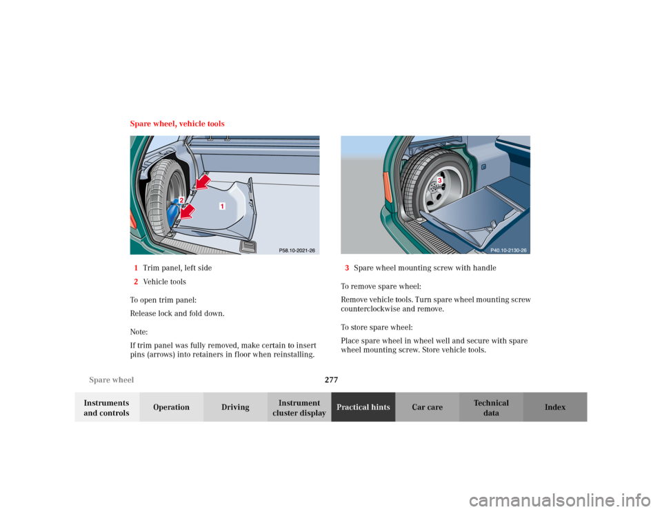
1Trim panel, left side
2Vehicle tools
To o pen tr im p an el :
Release lock and fold down.
Note:
If trim panel was fully removed, make certain to insert
pins (arrows) into retainers in floor when reinstalling.3Spare wheel mounting screw with handle
To remove spare wheel:
Remove vehicle tools. Turn spare wheel mounting screw
counterclockwise and remove.
To store spare wheel:
Place spare wheel in wheel well and secure with spare
wheel mounting screw. Store vehicle tools.
3
Page 292 of 354
289 Battery
Te ch n i c a l
data Instruments
and controlsOperation DrivingInstrument
cluster displayPractical hintsCar care Index Battery
Important!
Battery replacement information:
The maintenance-free battery is located under the rear
seat cushion. To minimize the chance for acid leakage
which could cause severe burns during a crash or
rollover, a special acid leakage resistant battery was
factory installed. A replacement battery for the vehicle must not leak acid when upside down for at least
15 minutes. Your authorized Mercedes-Benz Center can
provide such a special battery.
The service life of the battery is dependent on its
condition of charge. The battery should always be kept
sufficiently charged, in order to last an optimum length
of time.
Therefore, we strongly recommend that you have the
battery charge checked frequently, and corrected if
necessary, especially if you use the vehicle less than
approximately 200 miles (300 km) per month,
mostly for short distance trips, or if it is not used for
long periods of time.
Only charge a battery with a battery charger after the
battery has been disconnected from the vehicle’s
electrical circuit.
Always disconnect the battery negative lead first and
connect last.
When removing and connecting the battery, always
make sure that all electrical consumers are off and the
electronic key is in steering lock position 0. The battery,
its filler caps, the vent tube and the opposite plug must
always be securely installed when the vehicle in
operation.
Wa r n i n g !
Failure to follow these instructions can result in
severe injury or death.Never lean over batteries while connecting, you
might get injured.Battery fluid contains sulfuric acid. Do not allow
this fluid to come in contact with eyes, skin or
clothing. In case it does, immediately flush affected
area with water and seek medical help if necessary.A battery will also produce hydrogen gas, which is
flammable and explosive. Keep flames or sparks
away from battery, avoid improper connection of
jumper cables, smoking etc..
Page 298 of 354
295 Towing the vehicle
Te ch n i c a l
data Instruments
and controlsOperation DrivingInstrument
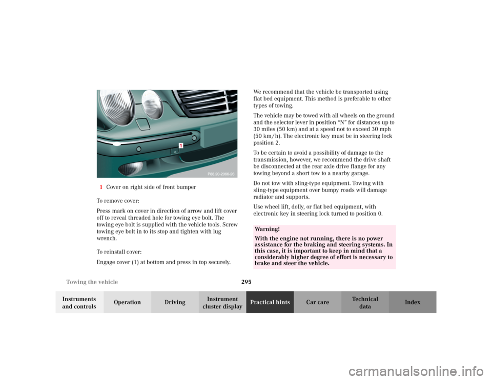
cluster displayPractical hintsCar care Index 1Cover on right side of front bumper
To remove cover:
Press mark on cover in direction of arrow and lift cover
off to reveal threaded hole for towing eye bolt. The
towing eye bolt is supplied with the vehicle tools. Screw
towing eye bolt in to its stop and tighten with lug
wrench.
To reinstall cover:
Engage cover (1) at bottom and press in top securely.We recommend that the vehicle be transported using
flat bed equipment. This method is preferable to other
types of towing.
The vehicle may be towed with all wheels on the ground
and the selector lever in position “N” for distances up to
30 miles (50 km) and at a speed not to exceed 30 mph
(50 km / h). The electronic key must be in steering lock
position 2.
To be certain to avoid a possibility of damage to the
transmission, however, we recommend the drive shaft
be disconnected at the rear axle drive flange for any
towing beyond a short tow to a nearby garage.
Do not tow with sling-type equipment. Towing with
sling-type equipment over bumpy roads will damage
radiator and supports.
Use wheel lift, dolly, or flat bed equipment, with
electronic key in steering lock turned to position 0.
Wa r n i n g !
With the engine not running, there is no power
assistance for the braking and steering systems. In
this case, it is important to keep in mind that a
considerably higher degree of effort is necessary to
brake and steer the vehicle.
Page 302 of 354
299 Exterior lamps
Te ch n i c a l
data Instruments
and controlsOperation DrivingInstrument
cluster displayPractical hintsCar care Index Bulbs for low beam
H7 (55 W)
Open hood.
Twist cover (1) counterclockwise and remove.
Pull off electrical connector (4).
Twist bulb holder counterclockwise and remove bulb
from it.
Insert the new bulb so that the base locates in the
recess on the holder.
Install bulb holder and twist clockwise to its stop, and
reinstall electrical connector.
Reinstall cover (1), twist it clockwise until seated
securely.
Xenon (optional)
Bulb for low beamBulbs for high beam
H7 (55 W)
Open hood.
Twist cover (2) counterclockwise and remove.
Pull off electrical connector.
Twist bulb holder counterclockwise and remove bulb
from it.
Insert the new bulb so that its base fits in recess of the
holder.
Install bulb holder and twist clockwise to its stop, and
reinstall electrical connector.Ensure that base is
secured on both sides (arrows)
Reinstall cover (2), twist it clockwise until seated
securely.
Wa r n i n g !
Because of high voltage in Xenon lamps, it is
dangerous to replace the bulb or repair the lamp
and its components. We recommend that you have
such work done by a qualified technician.
Page 314 of 354
311 Roof rack
Te ch n i c a l
data Instruments
and controlsOperation DrivingInstrument
cluster displayPractical hintsCar care Index Roof rack
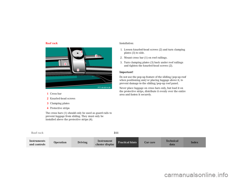
1Cross bar
2Knurled-head screws
3Clamping plates
4Protective strips
The cross bars (1) should only be used as guard rails to
prevent luggage from sliding. They must only be
installed above the protective strips (4).Installation:
1. Loosen knurled-head screws (2) and turn clamping
plates (3) to side.
2. Mount cross bar (1) on roof railings.
3. Turn clamping plates (3) back under roof railings
and tighten the knurled-head screws (2).
Important!
Do not use the pop-up feature of the sliding / pop-up roof
when positioning and / or placing luggage above it, to
prevent damage to the sliding / pop-up roof panel.
Never place luggage on cross bars only, but load it on
the protective strips, distribute it evenly over the entire
area and fasten it securely.
Page 315 of 354
312 Roof rack
Te ch n i c a l
data Instruments
and controlsOperation DrivingInstrument
cluster displayPractical hintsCar care Index
Long cargo items should not extend beyond the vehicle
length and should be securely fastened at the front and
rear.
Prior to and during an extended trip check the roof load,
and retighten the knurled-head screws if necessary.
The heaviest portion of the cargo should always be kept
as low as possible since it influences the handling
characteristics of the vehicle.
When driving without roof luggage, the cross bars may
be removed to reduce wind noise.
For load capacity see page 326.Note:
Use only roof racks approved by Mercedes-Benz. They
mount to the roof railings and do not require additional
supports (e.g. suction cups or legs). Such supports may
lead to marring of the paint or denting of the roof. For
further information inquire at your Mercedes-Benz
Center.
Page 346 of 354
343 Index
Te ch n i c a l
data Instruments
and controlsOperation DrivingInstrument
cluster displayPractical hints Car careIndex Multicontour seat ............................................................ 51
Multifunction display ...................................................... 92
Audio systems ............................................................. 97
Engine oil level indicator ........................................... 96
FSS (Flexible service system) ................................... 96
Individual settings .....................................................110
Malfunction message memory ............................... 108
Navigation system ..................................................... 105
Telephone ................................................................... 100
Trip and main odometer ............................................ 96
Trip computer ............................................................ 106
Vehicle speed ............................................................... 96
Multifunction steering wheel ........................................ 92
Setting the audio volume ..........................................113
NNavigation system -
Multifunctions display ............................................. 105
Night security Illumination ......................................... 120OOn-board diagnostic system .........................................244
Operator’s manual ............................................................. 8Outside temperature indicator ....................................... 90
Overhead control panel ................................................... 21
PPanic button ...................................................................... 31
Parcel net in front passenger footwell ........................ 179
Parking ............................................................................ 216
Parking assist (Parktronic) .......................................... 234
Malfunction ............................................................... 238
Parktronic switch ..................................................... 238
Sensors ...................................................................... 235
Warning indicators .................................................. 236
Parking brake ............................... 212, 214, 216, 231, 245
PA R K I N G B R A K E -
malfunction and warning messages ..................... 255
Power assistance ............................................................ 214
Power seats, front ............................................................. 42
Power windows ............................................................... 154
Blocking of rear door window operation ............... 155
Opening and closing ...................................................30
Synchronizing ........................................................... 156
Problems with your vehicle ............................................ 14
Product information .......................................................... 7