clock MERCEDES-BENZ E350 2010 W212 User Guide
[x] Cancel search | Manufacturer: MERCEDES-BENZ, Model Year: 2010, Model line: E350, Model: MERCEDES-BENZ E350 2010 W212Pages: 372, PDF Size: 8.55 MB
Page 318 of 372
the front passenger door and the rear
doors.
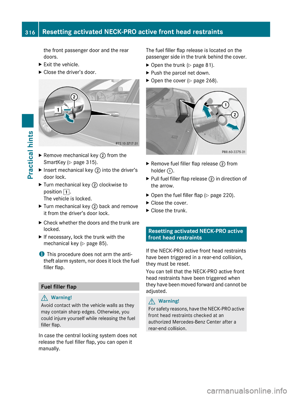
XExit the vehicle.XClose the driver’s door.XRemove mechanical key ; from the
SmartKey (Y page 315).
XInsert mechanical key ; into the driver’s
door lock.
XTurn mechanical key ; clockwise to
position 1.
The vehicle is locked.
XTurn mechanical key ; back and remove
it from the driver’s door lock.
XCheck whether the doors and the trunk are
locked.
XIf necessary, lock the trunk with the
mechanical key (Y page 85).
iThis procedure does not arm the anti-
theft alarm system, nor does it lock the fuel
filler flap.
Fuel filler flap
GWarning!
Avoid contact with the vehicle walls as they
may contain sharp edges. Otherwise, you
could injure yourself while releasing the fuel
filler flap.
In case the central locking system does not
release the fuel filler flap, you can open it
manually.
The fuel filler flap release is located on the
passenger side in the trunk behind the cover.
XOpen the trunk (Y page 81).XPush the parcel net down.XOpen the cover (Y page 268).XRemove fuel filler flap release ; from
holder :.
XPull fuel filler flap release ; in direction of
the arrow.
XOpen the fuel filler flap (Y page 220).XClose the cover.XClose the trunk.
Resetting activated NECK-PRO active
front head restraints
If the NECK-PRO active front head restraints
have been triggered in a rear-end collision,
they must be reset.
You can tell that the NECK-PRO active front
head restraints have been triggered when
they have been moved forward and cannot be
adjusted.
GWarning!
For safety reasons, have the NECK-PRO active
front head restraints checked at an
authorized Mercedes-Benz Center after a
rear-end collision.
316Resetting activated NECK-PRO active front head restraintsPractical hints
212_AKB; 2; 41, en-USd2ureepe,Version: 2.11.8.12009-07-17T09:14:21+02:00 - Seite 316
Page 322 of 372
recommended to have such work done by a
qualified technician.
Before you start to replace a bulb for a front
lamp, do the following:
XSwitch off the ignition.XTurn the exterior lamp switch to position
$.
XOpen the hood (Y page 223).
Releasing/fixing the washer fluid
reservoir
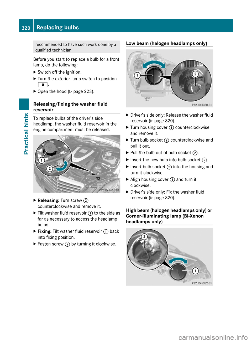
To replace bulbs of the driver’s side
headlamp, the washer fluid reservoir in the
engine compartment must be released.
XReleasing: Turn screw ;
counterclockwise and remove it.
XTilt washer fluid reservoir : to the side as
far as necessary to access the headlamp
bulbs.
XFixing: Tilt washer fluid reservoir : back
into fixing position.
XFasten screw ; by turning it clockwise.Low beam (halogen headlamps only)XDriver’s side only: Release the washer fluid
reservoir (Y page 320).
XTurn housing cover : counterclockwise
and remove it.
XTurn bulb socket ; counterclockwise and
pull it out.
XPull the bulb out of bulb socket ;.XInsert the new bulb into bulb socket ;.XInsert bulb socket ; into the housing and
turn it clockwise.
XAlign housing cover : and turn it
clockwise.
XDriver’s side only: Fix the washer fluid
reservoir (Y page 320).
High beam (halogen headlamps only) or
Corner-illuminating lamp (Bi-Xenon
headlamps only)
320Replacing bulbsPractical hints
212_AKB; 2; 41, en-USd2ureepe,Version: 2.11.8.12009-07-17T09:14:21+02:00 - Seite 320
Page 323 of 372
XDriver’s side only: Release the washer fluid
reservoir (Y page 320).
XTurn housing cover : counterclockwise
and remove it.
XTurn bulb socket ; counterclockwise and
pull it out.
XPull the bulb out of bulb socket ;.XInsert the new bulb into bulb socket ;.XInsert bulb socket ; into the housing and
turn it clockwise.
XAlign housing cover : and turn it
clockwise.
XDriver’s side only: Fix the washer fluid
reservoir (Y page 320).
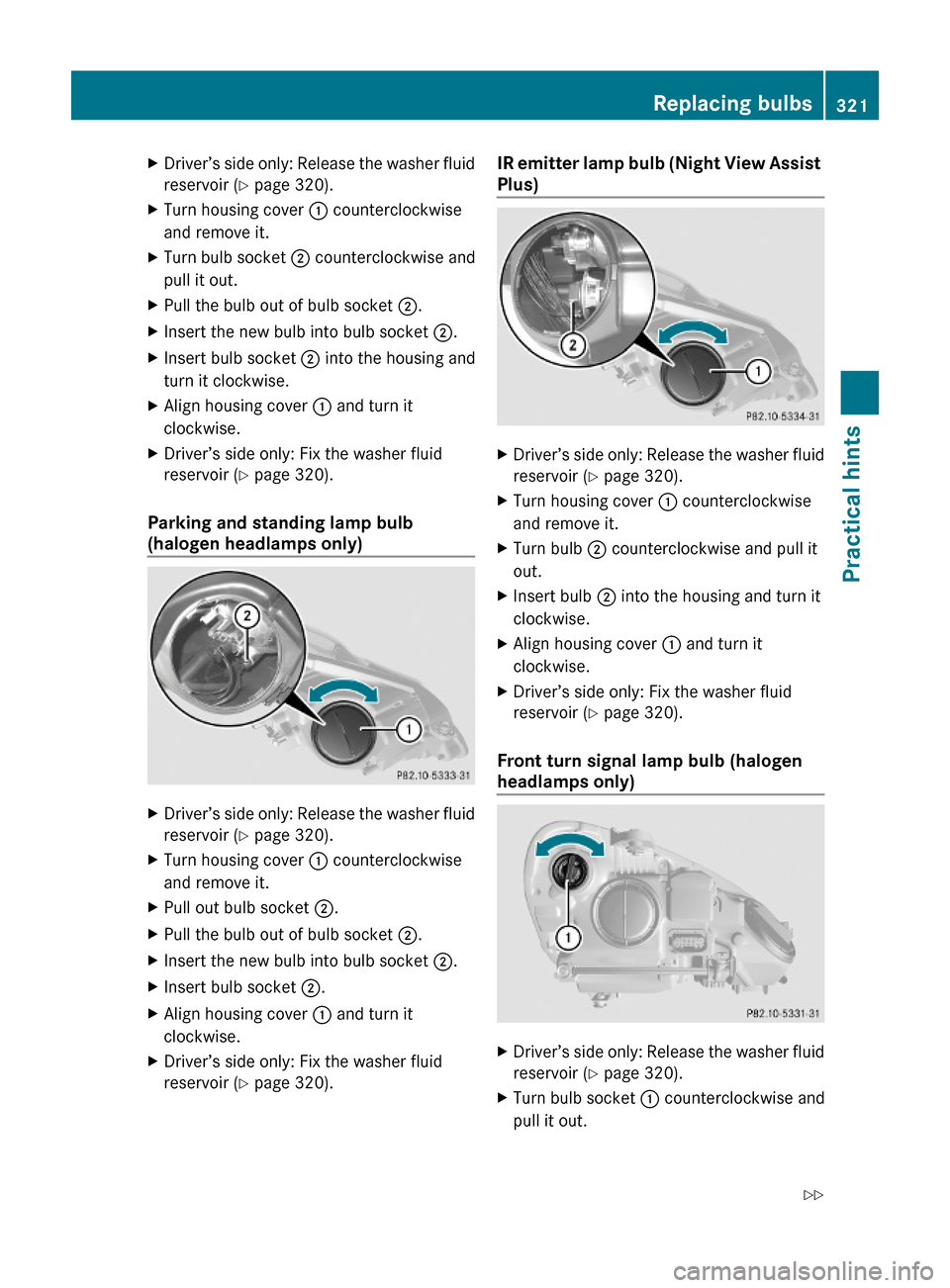
Parking and standing lamp bulb
(halogen headlamps only)
XDriver’s side only: Release the washer fluid
reservoir (Y page 320).
XTurn housing cover : counterclockwise
and remove it.
XPull out bulb socket ;.XPull the bulb out of bulb socket ;.XInsert the new bulb into bulb socket ;.XInsert bulb socket ;.XAlign housing cover : and turn it
clockwise.
XDriver’s side only: Fix the washer fluid
reservoir (Y page 320).
IR emitter lamp bulb (Night View Assist
Plus)
XDriver’s side only: Release the washer fluid
reservoir (Y page 320).
XTurn housing cover : counterclockwise
and remove it.
XTurn bulb ; counterclockwise and pull it
out.
XInsert bulb ; into the housing and turn it
clockwise.
XAlign housing cover : and turn it
clockwise.
XDriver’s side only: Fix the washer fluid
reservoir (Y page 320).
Front turn signal lamp bulb (halogen
headlamps only)
XDriver’s side only: Release the washer fluid
reservoir (Y page 320).
XTurn bulb socket : counterclockwise and
pull it out.
Replacing bulbs321Practical hints212_AKB; 2; 41, en-USd2ureepe,Version: 2.11.8.12009-07-17T09:14:21+02:00 - Seite 321Z
Page 324 of 372
XTurn the bulb counterclockwise with light
pressure and pull it out of bulb socket :.
XInsert the new bulb into bulb socket : and
turn the bulb clockwise.
XInsert bulb socket : into the housing and
turn it clockwise.
XDriver’s side only: Fix the washer fluid
reservoir (Y page 320).
Replacing wiper blades
Safety notes
GWarning!
For safety reasons, switch off the wipers and
remove the SmartKey from the starter switch
(vehicles with KEYLESS-GO: Make sure the
vehicle’s on-board electronics have status 0)
before replacing a wiper blade. Otherwise, the
wiper motor could suddenly turn on and cause
injury.
GWarning!
Wiper blades are components that are subject
to wear and tear. Replace the wiper blades
twice a year, preferably in the spring and fall.
Otherwise the windshield will not be wiped
properly. As a result, you may not be able to
observe surrounding traffic conditions and
could cause an accident.
! Never open the hood when a wiper arm is
folded forward.
Hold on to the wiper when folding a wiper
arm back. If released, the force of the
impact from the tensioning spring could
crack the windshield.
Do not allow a wiper arm to contact the
windshield glass without a wiper blade
inserted.
Mercedes-Benz recommends that you have
this work carried out at an authorized
Mercedes-Benz Center.
XRemove the SmartKey from the starter
switch.
Vehicles with KEYLESS-GO:XMake sure the vehicle’s on-board
electronics have status 0 (Y page 86).
Removing wiper blades
! Do not pull on the wiper blade inserts.
They could tear.
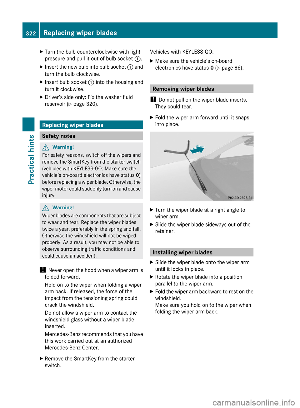
XFold the wiper arm forward until it snaps
into place.
XTurn the wiper blade at a right angle to
wiper arm.
XSlide the wiper blade sideways out of the
retainer.
Installing wiper blades
XSlide the wiper blade onto the wiper arm
until it locks in place.
XRotate the wiper blade into a position
parallel to the wiper arm.
XFold the wiper arm backward to rest on the
windshield.
Make sure you hold on to the wiper when
folding the wiper arm back.
322Replacing wiper bladesPractical hints
212_AKB; 2; 41, en-USd2ureepe,Version: 2.11.8.12009-07-17T09:14:21+02:00 - Seite 322
Page 327 of 372
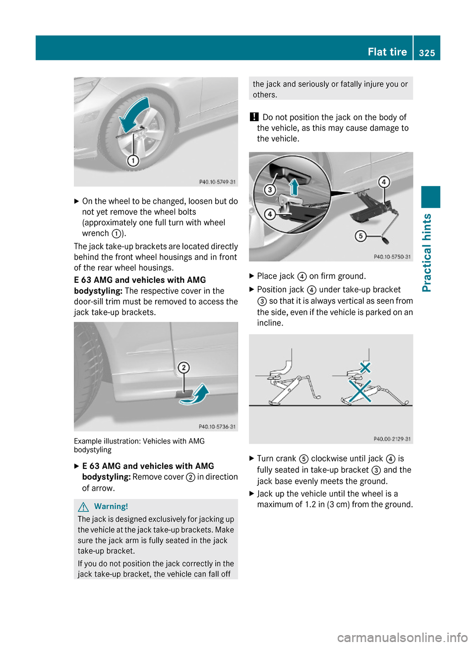
XOn the wheel to be changed, loosen but do
not yet remove the wheel bolts
(approximately one full turn with wheel
wrench :).
The jack take-up brackets are located directly
behind the front wheel housings and in front
of the rear wheel housings.
E 63 AMG and vehicles with AMG
bodystyling: The respective cover in the
door-sill trim must be removed to access the
jack take-up brackets.
Example illustration: Vehicles with AMGbodystyling
XE 63 AMG and vehicles with AMG
bodystyling: Remove cover ; in direction
of arrow.
GWarning!
The jack is designed exclusively for jacking up
the vehicle at the jack take-up brackets. Make
sure the jack arm is fully seated in the jack
take-up bracket.
If you do not position the jack correctly in the
jack take-up bracket, the vehicle can fall off
the jack and seriously or fatally injure you or
others.
! Do not position the jack on the body of
the vehicle, as this may cause damage to
the vehicle.
XPlace jack ? on firm ground.XPosition jack ? under take-up bracket
= so that it is always vertical as seen from
the side, even if the vehicle is parked on an
incline.
XTurn crank A clockwise until jack ? is
fully seated in take-up bracket = and the
jack base evenly meets the ground.
XJack up the vehicle until the wheel is a
maximum of 1.2 in (3 cm) from the ground.
Flat tire325Practical hints212_AKB; 2; 41, en-USd2ureepe,Version: 2.11.8.12009-07-17T09:14:21+02:00 - Seite 325Z
Page 330 of 372
XTurn the SmartKey in the starter switch to
position 1.
or
XVehicles with KEYLESS-GO: Press the
KEYLESS-GO start/stop button once. Do
not depress the brake pedal.
XPress I on electric air pump switch ;.
The electric air pump switches on and
inflates the collapsible tire.
XInflate the collapsible tire to the
recommended tire inflation pressure as
specified for your vehicle (Y page 358).
This should take approximately 5 minutes.
GWarning!
The air hose and the union nut can become
hot during inflation. Exercise proper caution
to avoid burning yourself when using the
equipment.
! Do not operate the electric air pump
longer than 8 minutes without interruption.
Otherwise it may overheat.
You may operate the air pump again after
it has cooled off.
! Compare the recommended tire inflation
pressure for your vehicle with the tire
inflation pressure on the yellow label
located on the spare wheel rim.
If the tire inflation pressure on the yellow
label on the spare wheel rim differs from
the values given in this Operator’s Manual,
inflate the tire to the recommended tire
inflation pressure given on the yellow label
on the spare wheel rim.
XPress 0 on electric air pump switch ;.XTurn the SmartKey in the starter switch to
position 0.
or
XVehicles with KEYLESS-GO: Press the
KEYLESS-GO start/stop button twice. Do
not depress the brake pedal.
XVersion 1 only: If the tire inflation pressure
is above the recommended tire inflation
pressure as specified for your vehicle
(Y page 358), decrease tire pressure using
the vent screw on air hose ?.
XVersion 2 only: If the tire inflation pressure
is above the recommended tire inflation
pressure as specified for your vehicle
(Y page 358), decrease tire pressure using
deflate button B.
GObserve Safety notes, see page 231.XDetach the electric air pump.XReinstall collapsible tire valve cap.XVersion 1 only: Store electrical plug =
and air hose ? behind flap :.
XVersion 2 only: Store electrical plug =
and the air hose back into the pump
housing bottom.
XPlace the electric air pump back in its
designated storage space.
XLower the vehicle.
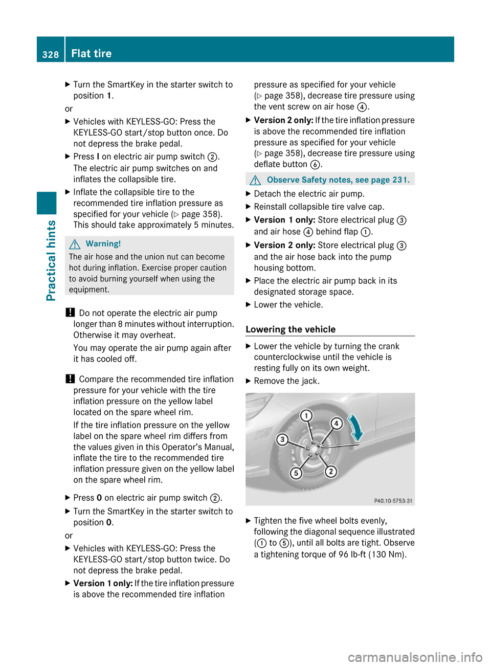
Lowering the vehicle
XLower the vehicle by turning the crank
counterclockwise until the vehicle is
resting fully on its own weight.
XRemove the jack.XTighten the five wheel bolts evenly,
following the diagonal sequence illustrated
(: to A), until all bolts are tight. Observe
a tightening torque of 96 lb-ft (130 Nm).
328Flat tirePractical hints
212_AKB; 2; 41, en-USd2ureepe,Version: 2.11.8.12009-07-17T09:14:21+02:00 - Seite 328
Page 337 of 372
For more information on AdBlue®, see
(Y page 364).
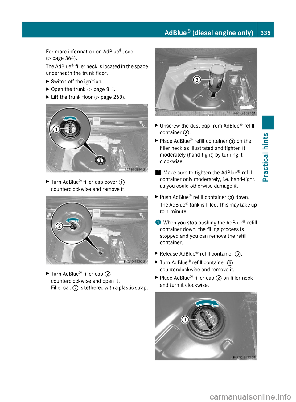
The AdBlue® filler neck is located in the space
underneath the trunk floor.
XSwitch off the ignition.XOpen the trunk (Y page 81).XLift the trunk floor (Y page 268).XTurn AdBlue® filler cap cover :
counterclockwise and remove it.
XTurn AdBlue® filler cap ;
counterclockwise and open it.
Filler cap ; is tethered with a plastic strap.
XUnscrew the dust cap from AdBlue® refill
container =.
XPlace AdBlue® refill container = on the
filler neck as illustrated and tighten it
moderately (hand-tight) by turning it
clockwise.
! Make sure to tighten the AdBlue® refill
container only moderately, i.e. hand-tight,
as you could otherwise damage it.
XPush AdBlue® refill container = down.
The AdBlue® tank is filled. This may take up
to 1 minute.
iWhen you stop pushing the AdBlue® refill
container down, the filling process is
stopped and you can remove the refill
container.
XRelease AdBlue® refill container =.XTurn AdBlue® refill container =
counterclockwise and remove it.
XPlace AdBlue® filler cap ; on filler neck
and turn it clockwise.
AdBlue® (diesel engine only)335Practical hints212_AKB; 2; 41, en-USd2ureepe,Version: 2.11.8.12009-07-17T09:14:21+02:00 - Seite 335Z
Page 338 of 372
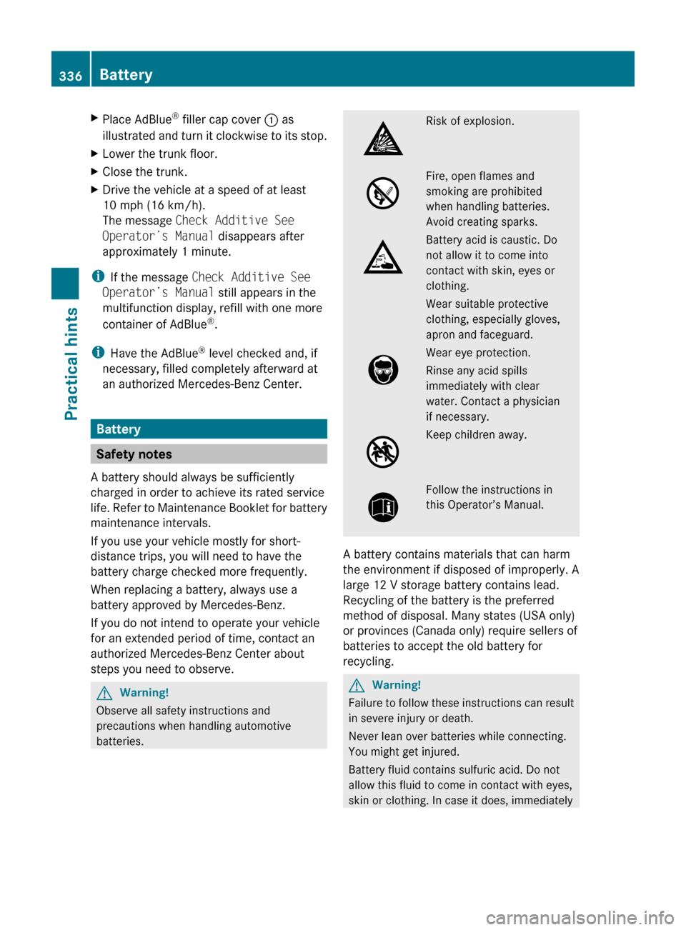
XPlace AdBlue® filler cap cover : as
illustrated and turn it clockwise to its stop.
XLower the trunk floor.XClose the trunk.XDrive the vehicle at a speed of at least
10 mph (16 km/h).
The message Check Additive See
Operator’s Manual disappears after
approximately 1 minute.
iIf the message Check Additive See
Operator’s Manual still appears in the
multifunction display, refill with one more
container of AdBlue®.
iHave the AdBlue® level checked and, if
necessary, filled completely afterward at
an authorized Mercedes-Benz Center.
Battery
Safety notes
A battery should always be sufficiently
charged in order to achieve its rated service
life. Refer to Maintenance Booklet for battery
maintenance intervals.
If you use your vehicle mostly for short-
distance trips, you will need to have the
battery charge checked more frequently.
When replacing a battery, always use a
battery approved by Mercedes-Benz.
If you do not intend to operate your vehicle
for an extended period of time, contact an
authorized Mercedes-Benz Center about
steps you need to observe.
GWarning!
Observe all safety instructions and
precautions when handling automotive
batteries.
Risk of explosion.Fire, open flames and
smoking are prohibited
when handling batteries.
Avoid creating sparks.
Battery acid is caustic. Do
not allow it to come into
contact with skin, eyes or
clothing.
Wear suitable protective
clothing, especially gloves,
apron and faceguard.
Wear eye protection.
Rinse any acid spills
immediately with clear
water. Contact a physician
if necessary.
Keep children away.Follow the instructions in
this Operator’s Manual.
A battery contains materials that can harm
the environment if disposed of improperly. A
large 12 V storage battery contains lead.
Recycling of the battery is the preferred
method of disposal. Many states (USA only)
or provinces (Canada only) require sellers of
batteries to accept the old battery for
recycling.
GWarning!
Failure to follow these instructions can result
in severe injury or death.
Never lean over batteries while connecting.
You might get injured.
Battery fluid contains sulfuric acid. Do not
allow this fluid to come in contact with eyes,
skin or clothing. In case it does, immediately
336BatteryPractical hints
212_AKB; 2; 41, en-USd2ureepe,Version: 2.11.8.12009-07-17T09:14:21+02:00 - Seite 336
Page 343 of 372
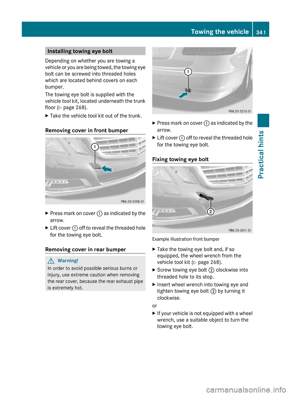
Installing towing eye bolt
Depending on whether you are towing a
vehicle or you are being towed, the towing eye
bolt can be screwed into threaded holes
which are located behind covers on each
bumper.
The towing eye bolt is supplied with the
vehicle tool kit, located underneath the trunk
floor (Y page 268).
XTake the vehicle tool kit out of the trunk.
Removing cover in front bumper
XPress mark on cover : as indicated by the
arrow.
XLift cover : off to reveal the threaded hole
for the towing eye bolt.
Removing cover in rear bumper
GWarning!
In order to avoid possible serious burns or
injury, use extreme caution when removing
the rear cover, because the rear exhaust pipe
is extremely hot.
XPress mark on cover : as indicated by the
arrow.
XLift cover : off to reveal the threaded hole
for the towing eye bolt.
Fixing towing eye bolt
Example illustration front bumper
XTake the towing eye bolt and, if so
equipped, the wheel wrench from the
vehicle tool kit (Y page 268).
XScrew towing eye bolt ; clockwise into
threaded hole to its stop.
XInsert wheel wrench into towing eye and
tighten towing eye bolt ; by turning it
clockwise.
or
XIf your vehicle is not equipped with a wheel
wrench, use a suitable object to turn the
towing eye bolt.
Towing the vehicle341Practical hints212_AKB; 2; 41, en-USd2ureepe,Version: 2.11.8.12009-07-17T09:14:21+02:00 - Seite 341Z
Page 344 of 372
Removing towing eye boltXLoosen towing eye bolt ; by turning it
counterclockwise.XUnscrew towing eye bolt ;.XReinstalling cover: Fit cover :
( Y page 341) and snap it into place.XStore the towing eye bolt ; and wheel
wrench back into the vehicle tool kit.
Towing with one axle raised
! The vehicle may be towed only for
distances up to 30 miles (50 km) and at a
speed not to exceed 30 mph (50 km/h).
! Vehicles with 4MATIC: Do not tow with
one axle raised. Doing so could damage the
transfer case, which is not covered by the
Mercedes-Benz Limited Warranty.
All wheels must be on or off the ground.
Observe instructions for towing the vehicle
with all wheels on the ground.
XMake sure the ignition is switched on.XWith the vehicle at a standstill, depress the
brake pedal and keep it pressed.XRelease the brake pedal.XIf engaged, release the parking brake.XSwitch off the automatic central locking
( Y page 144).XSwitch off the ignition and leave the
SmartKey in the starter switch.XSwitch on the hazard warning flasher
( Y page 101).
!
Because the ESC operates automatically,
the engine and ignition must be shut off
(SmartKey in starter switch position 0 or
1 or KEYLESS-GO start/stop button in
position 0 or 1) when the vehicle is being
towed with one axle raised.
Active braking action through the ESC may
otherwise seriously damage the brake
system which is not covered by the
Mercedes-Benz Limited Warranty.
Towing with all wheels on the groundGWarning!
If circumstances require towing the vehicle
with all wheels on the ground, always tow with
a tow bar if:
R the engine will not run
R there is a malfunction in the brake system
R there is a malfunction in the power supply
or in the vehicle’s electrical system
This is necessary to adequately control the
towed vehicle.
Prior to towing the vehicle with all wheels on
the ground, make sure the SmartKey is in
starter switch position 2.
If the SmartKey is left in the starter switch
position 0 for an extended period of time, it
can no longer be turned in the switch. In this
case, the steering is locked. To unlock,
remove SmartKey from starter switch and
reinsert.
GWarning!
With the engine not running, there is no power
assistance for the brake and steering
systems. In this case, it is important to keep
in mind that a considerably higher degree of
effort is necessary to brake and steer the
vehicle. Adapt your driving accordingly.
XMake sure the ignition is switched on.XWith the vehicle at a standstill, depress the
brake pedal and keep it pressed.XShift the automatic transmission into
neutral position N.XRelease the brake pedal.XIf engaged, release the parking brake.XSwitch on the hazard warning flasher
( Y page 101).
!
The vehicle may be towed only for
distances up to 30 miles (50 km) and at a
speed not to exceed 30 mph (50 km/h).
342Towing the vehiclePractical hints
212_AKB; 2; 41, en-USd2ureepe,Version: 2.11.8.12009-07-17T09:14:21+02:00 - Seite 342