MERCEDES-BENZ E63AMG 2010 W212 Owner's Manual
Manufacturer: MERCEDES-BENZ, Model Year: 2010, Model line: E63AMG, Model: MERCEDES-BENZ E63AMG 2010 W212Pages: 372, PDF Size: 8.55 MB
Page 341 of 372
power by an external battery or starter
pack.
RJump starting should only be performed
when the engine and catalytic converter22
are cold.
RDo not jump start the engine or charge the
battery if the battery is frozen. Let the
battery thaw out first.
ROnly jump start from batteries with the
same voltage rating (12 V). Jump starting
with a more powerful battery could damage
the vehicle’s electrical system. Such
damage will not be covered by the
Mercedes-Benz Limited Warranty.
ROnly use jumper cables with sufficient
cross-section and insulated terminal
clamps.
RAlways make sure the jumper cables are
not on or near pulleys, fans or other parts
that move when an engine is started or
running.
RShould the battery be drained completely,
let the donating power source charge the
vehicle for several minutes before
reattempting the starting process.
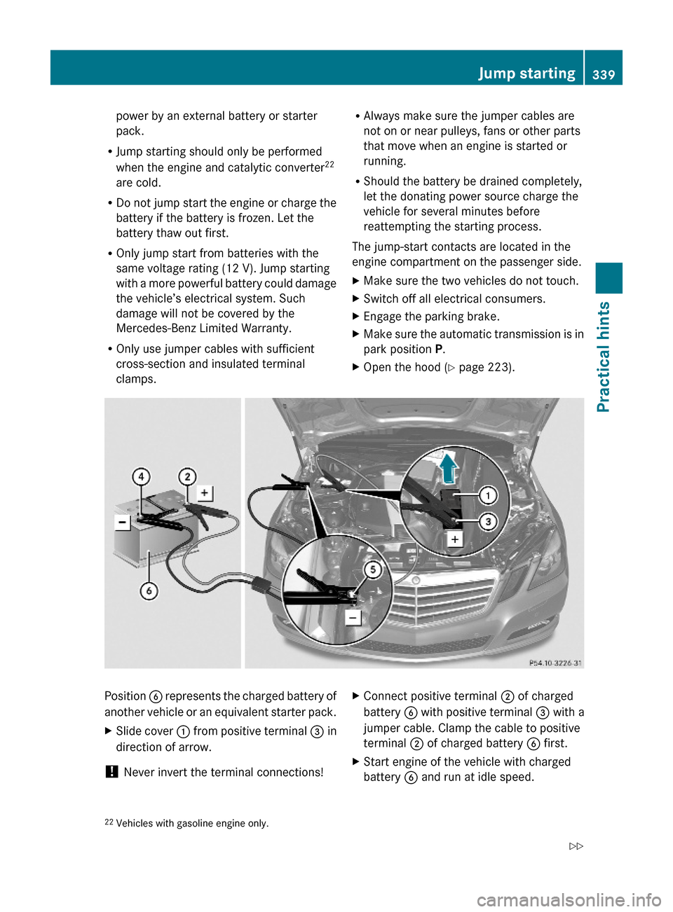
The jump-start contacts are located in the
engine compartment on the passenger side.
XMake sure the two vehicles do not touch.XSwitch off all electrical consumers.XEngage the parking brake.XMake sure the automatic transmission is in
park position P.
XOpen the hood (Y page 223).Position B represents the charged battery of
another vehicle or an equivalent starter pack.
XSlide cover : from positive terminal = in
direction of arrow.
! Never invert the terminal connections!
XConnect positive terminal ; of charged
battery B with positive terminal = with a
jumper cable. Clamp the cable to positive
terminal ; of charged battery B first.
XStart engine of the vehicle with charged
battery B and run at idle speed.22Vehicles with gasoline engine only.Jump starting339Practical hints212_AKB; 2; 41, en-USd2ureepe,Version: 2.11.8.12009-07-17T09:14:21+02:00 - Seite 339Z
Page 342 of 372
XConnect negative terminal ? of charged
battery B with negative terminal A with
a jumper cable. Clamp the cable to
negative terminal ? of charged battery
B first.XStart engine of the vehicle with the
discharged battery and run at idle speed.
You can now turn on the electrical
consumers. Do not switch on the
headlamps under any circumstances.XRemove the jumper cables from negative
terminals ? and A first.XRemove the jumper cables from positive
terminals ; and =.
You can now switch on the headlamps.XSlide cover : from positive terminal =
back.XHave the battery checked at the nearest
authorized Mercedes-Benz Center.
Towing the vehicle
Safety notes
GWarning!
The vehicle is braked when the HOLD function
or DISTRONIC PLUS is activated. Therefore,
deactivate the HOLD function or DISTRONIC
PLUS if the vehicle is to be towed.
Mercedes-Benz recommends that the vehicle
be transported with all wheels off the ground
using flatbed or appropriate wheel lift/dolly
equipment. This method is preferable to other
types of towing.
! To prevent damage during transport, do
not tie down vehicle by its chassis or
suspension parts.
If circumstances do not permit the
recommended towing methods, the vehicle
may be towed with all wheels on the ground
or front axle raised (except vehicles with
4MATIC) only so far as necessary to have the
vehicle moved to a safe location where the
recommended towing methods can be
employed.
! Before towing the vehicle observe the
following instructions:
R Do not tow-start the vehicle. You could
otherwise seriously damage the
automatic transmission which is not
covered by the Mercedes-Benz Limited
Warranty.
R Do not tow with sling-type equipment.
Towing with sling-type equipment over
bumpy roads will damage radiator and
supports.
R Towing of the vehicle should only be
done using the properly installed towing
eye bolt. Never attach a tow cable, tow
rope or tow rod to the vehicle chassis,
frame or suspension parts.GWarning!
With the engine not running, there is no power
assistance for the brake and steering
systems. In this case, it is important to keep
in mind that a considerably higher degree of
effort is necessary to brake and steer the
vehicle. Adapt your driving accordingly.
! Avoid pulling the vehicle abruptly or
diagonally, since it could result in damage
to the chassis alignment.
! Do not use the towing eye bolt for
recovery, as this could damage the vehicle.
If in doubt, recover the vehicle with a crane.
i If the battery is disconnected or
discharged
R the SmartKey will not turn in the starter
switch
R the automatic transmission will remain in
park position P
For more information see “Battery”
( Y page 336) or “Jump starting”
( Y page 338).
340Towing the vehiclePractical hints
212_AKB; 2; 41, en-USd2ureepe,Version: 2.11.8.12009-07-17T09:14:21+02:00 - Seite 340
Page 343 of 372
Installing towing eye bolt
Depending on whether you are towing a
vehicle or you are being towed, the towing eye
bolt can be screwed into threaded holes
which are located behind covers on each
bumper.
The towing eye bolt is supplied with the
vehicle tool kit, located underneath the trunk
floor (Y page 268).
XTake the vehicle tool kit out of the trunk.
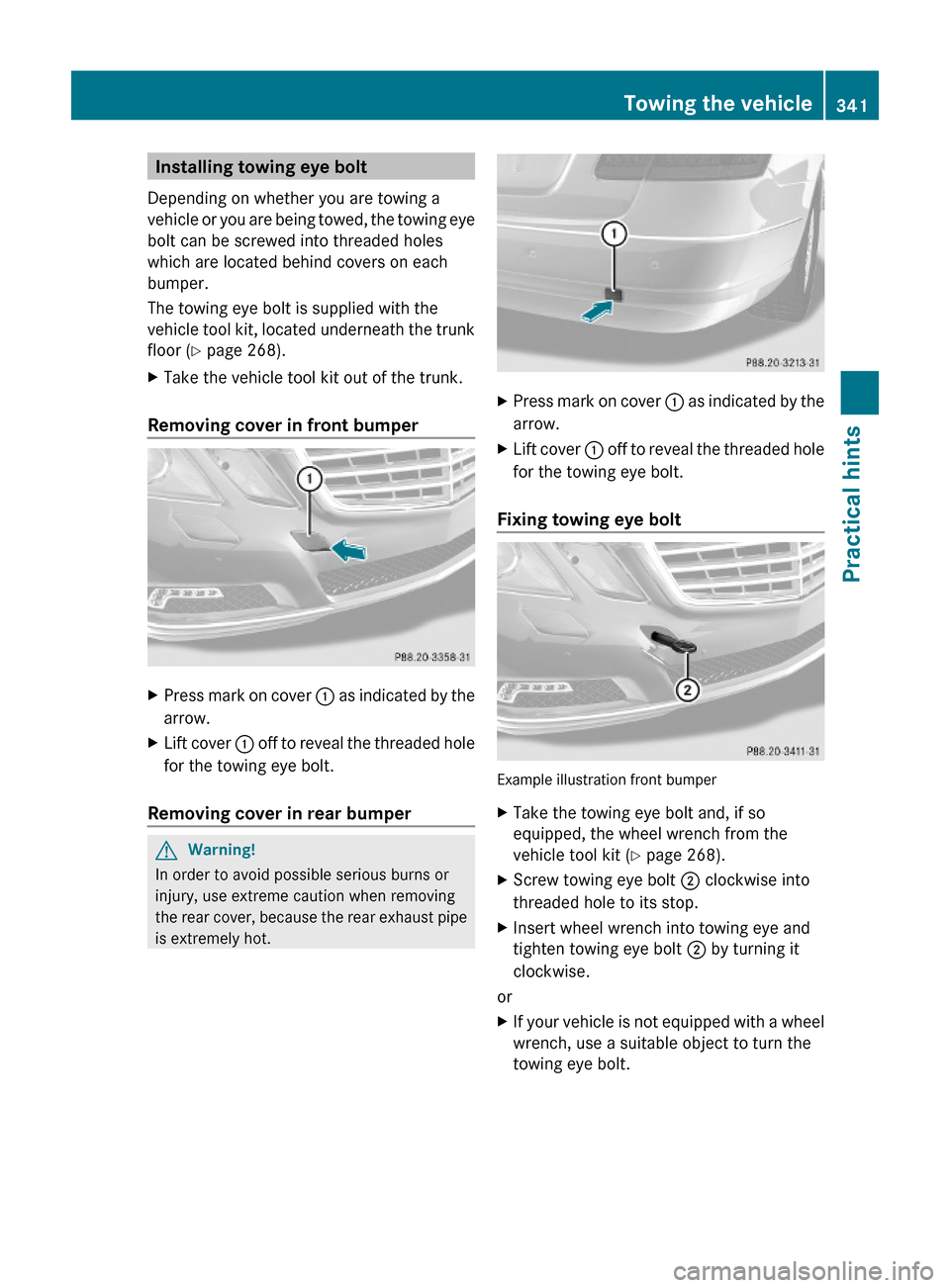
Removing cover in front bumper
XPress mark on cover : as indicated by the
arrow.
XLift cover : off to reveal the threaded hole
for the towing eye bolt.
Removing cover in rear bumper
GWarning!
In order to avoid possible serious burns or
injury, use extreme caution when removing
the rear cover, because the rear exhaust pipe
is extremely hot.
XPress mark on cover : as indicated by the
arrow.
XLift cover : off to reveal the threaded hole
for the towing eye bolt.
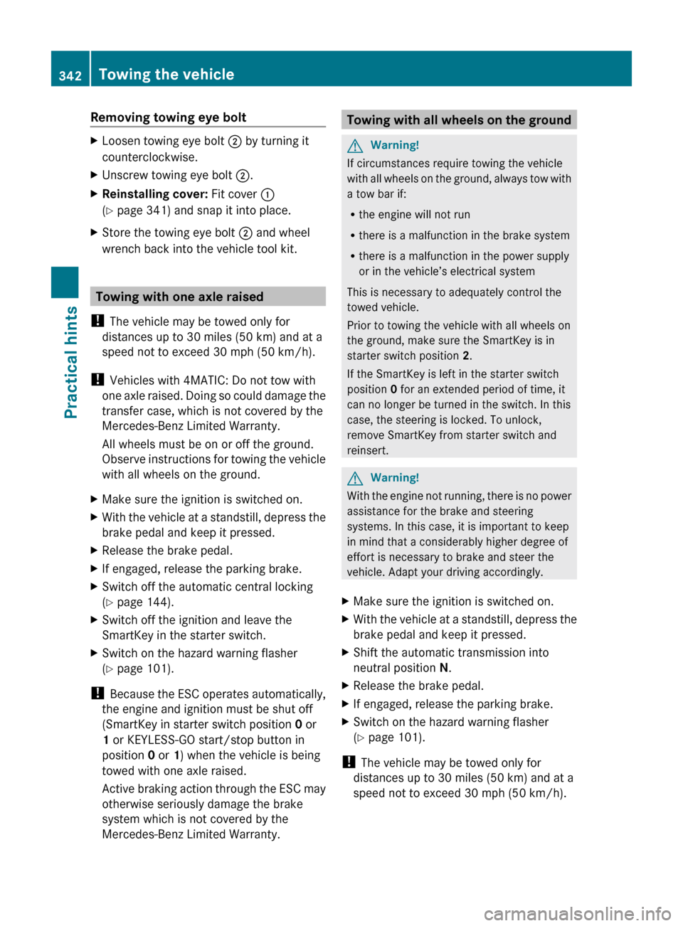
Fixing towing eye bolt
Example illustration front bumper
XTake the towing eye bolt and, if so
equipped, the wheel wrench from the
vehicle tool kit (Y page 268).
XScrew towing eye bolt ; clockwise into
threaded hole to its stop.
XInsert wheel wrench into towing eye and
tighten towing eye bolt ; by turning it
clockwise.
or
XIf your vehicle is not equipped with a wheel
wrench, use a suitable object to turn the
towing eye bolt.
Towing the vehicle341Practical hints212_AKB; 2; 41, en-USd2ureepe,Version: 2.11.8.12009-07-17T09:14:21+02:00 - Seite 341Z
Page 344 of 372
Removing towing eye boltXLoosen towing eye bolt ; by turning it
counterclockwise.XUnscrew towing eye bolt ;.XReinstalling cover: Fit cover :
( Y page 341) and snap it into place.XStore the towing eye bolt ; and wheel
wrench back into the vehicle tool kit.
Towing with one axle raised
! The vehicle may be towed only for
distances up to 30 miles (50 km) and at a
speed not to exceed 30 mph (50 km/h).
! Vehicles with 4MATIC: Do not tow with
one axle raised. Doing so could damage the
transfer case, which is not covered by the
Mercedes-Benz Limited Warranty.
All wheels must be on or off the ground.
Observe instructions for towing the vehicle
with all wheels on the ground.
XMake sure the ignition is switched on.XWith the vehicle at a standstill, depress the
brake pedal and keep it pressed.XRelease the brake pedal.XIf engaged, release the parking brake.XSwitch off the automatic central locking
( Y page 144).XSwitch off the ignition and leave the
SmartKey in the starter switch.XSwitch on the hazard warning flasher
( Y page 101).
!
Because the ESC operates automatically,
the engine and ignition must be shut off
(SmartKey in starter switch position 0 or
1 or KEYLESS-GO start/stop button in
position 0 or 1) when the vehicle is being
towed with one axle raised.
Active braking action through the ESC may
otherwise seriously damage the brake
system which is not covered by the
Mercedes-Benz Limited Warranty.
Towing with all wheels on the groundGWarning!
If circumstances require towing the vehicle
with all wheels on the ground, always tow with
a tow bar if:
R the engine will not run
R there is a malfunction in the brake system
R there is a malfunction in the power supply
or in the vehicle’s electrical system
This is necessary to adequately control the
towed vehicle.
Prior to towing the vehicle with all wheels on
the ground, make sure the SmartKey is in
starter switch position 2.
If the SmartKey is left in the starter switch
position 0 for an extended period of time, it
can no longer be turned in the switch. In this
case, the steering is locked. To unlock,
remove SmartKey from starter switch and
reinsert.
GWarning!
With the engine not running, there is no power
assistance for the brake and steering
systems. In this case, it is important to keep
in mind that a considerably higher degree of
effort is necessary to brake and steer the
vehicle. Adapt your driving accordingly.
XMake sure the ignition is switched on.XWith the vehicle at a standstill, depress the
brake pedal and keep it pressed.XShift the automatic transmission into
neutral position N.XRelease the brake pedal.XIf engaged, release the parking brake.XSwitch on the hazard warning flasher
( Y page 101).
!
The vehicle may be towed only for
distances up to 30 miles (50 km) and at a
speed not to exceed 30 mph (50 km/h).
342Towing the vehiclePractical hints
212_AKB; 2; 41, en-USd2ureepe,Version: 2.11.8.12009-07-17T09:14:21+02:00 - Seite 342
Page 345 of 372
iWhile being towed with the hazard
warning flasher in use, use the combination
switch in the usual manner to signal turns.
Only the selected turn signal will operate.
Upon canceling the turn signal, the hazard
warning flasher will operate again.
Fuses
Introduction
The electrical fuses in your vehicle serve to
switch off malfunctioning power circuits.
If a fuse is blown, the components and
systems secured by that fuse will stop
operating.
GWarning!
Only use fuses approved by Mercedes-Benz
with the specified amperage for the system in
question and do not attempt to repair or
bridge a blown fuse. Using other than
approved fuses or using repaired or bridged
fuses may cause an overload leading to a fire,
and/or cause damage to electrical
components and/or systems. Have the cause
determined and remedied by an authorized
Mercedes-Benz Center.
A blown fuse must be replaced by an
appropriate spare fuse (recognizable by its
color or the fuse rating given on the fuse) of
the amperage recommended in the fuse
chart. Any Mercedes-Benz Center will be glad
to advise you on this subject.
iIn case of a blown fuse contact Roadside
Assistance or an authorized Mercedes-
Benz Center.
If a newly inserted fuse blows again, have the
cause determined and rectified by an
authorized Mercedes-Benz Center.
The fuse chart is located in the trunk with the
vehicle tool kit (Y page 268). The fuse chart
explains the fuse allocation and fuse
amperages.
Before replacing fusesXEngage the parking brake.XMake sure the automatic transmission is in
park position P.
The transmission position indicator in the
multifunction display should be on P.
XSwitch off all electrical consumers.XTurn off the engine.XRemove the SmartKey from the starter
switch.
XVehicles with KEYLESS-GO: Open the
driver’s door (this puts the starter switch in
position 0, same as with the SmartKey
removed from the starter switch). The
driver’s door then can be closed again.
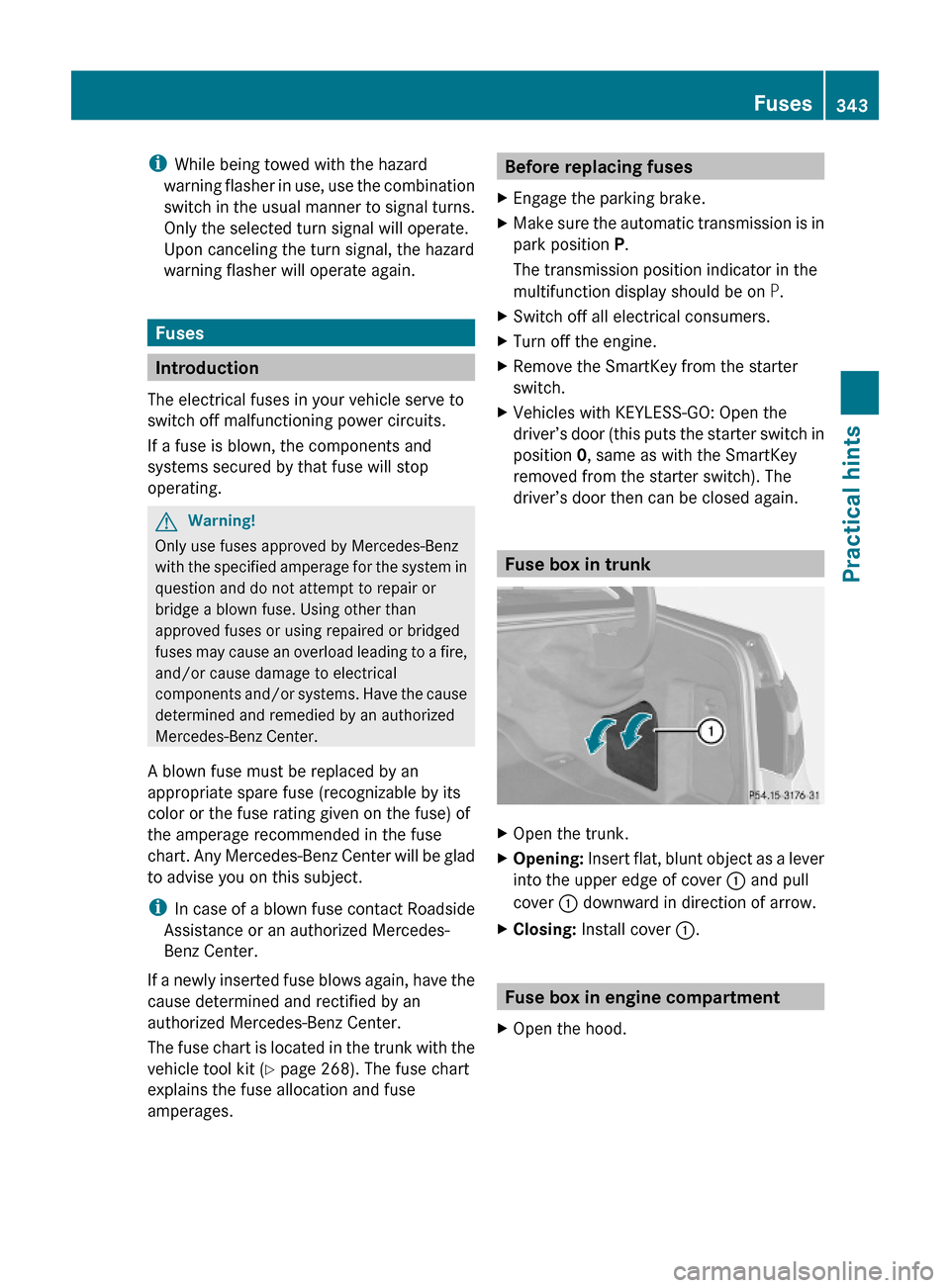
Fuse box in trunk
XOpen the trunk.XOpening: Insert flat, blunt object as a lever
into the upper edge of cover : and pull
cover : downward in direction of arrow.
XClosing: Install cover :.
Fuse box in engine compartment
XOpen the hood.Fuses343Practical hints212_AKB; 2; 41, en-USd2ureepe,Version: 2.11.8.12009-07-17T09:14:21+02:00 - Seite 343Z
Page 346 of 372
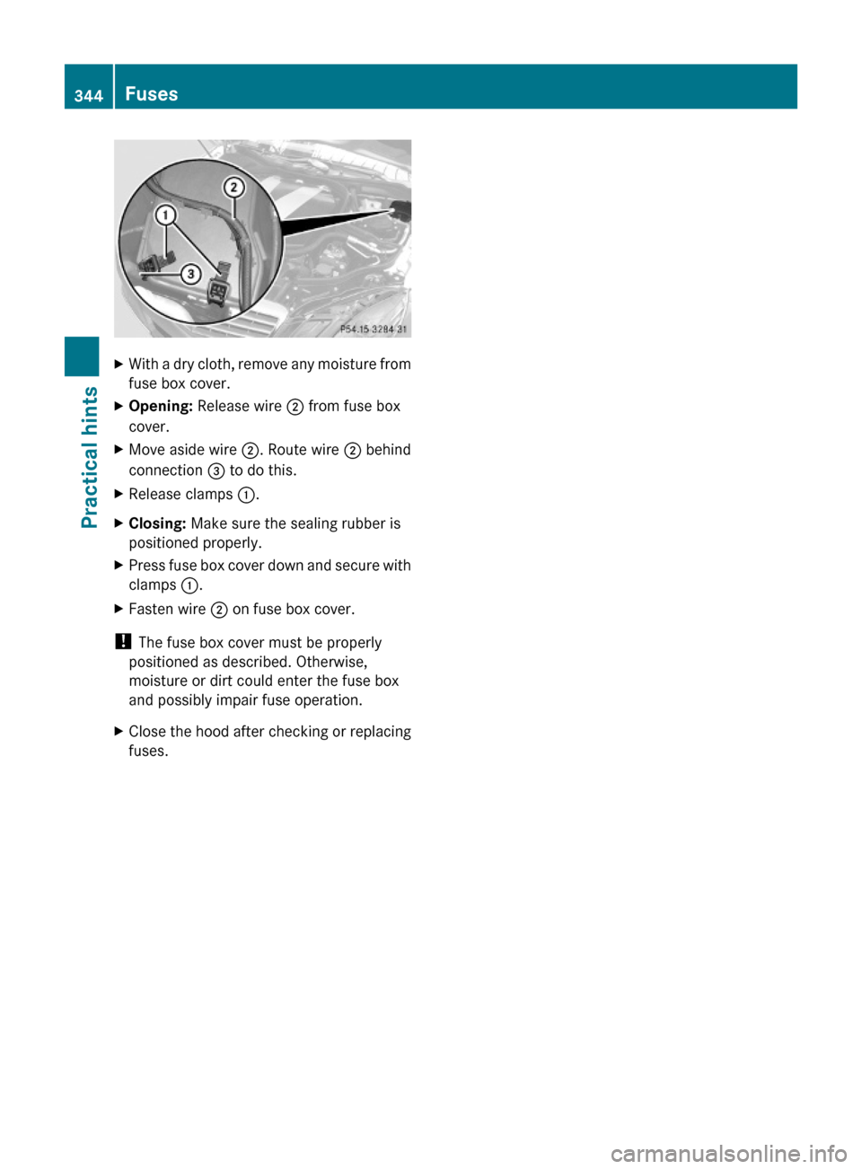
XWith a dry cloth, remove any moisture from
fuse box cover.
XOpening: Release wire ; from fuse box
cover.
XMove aside wire ;. Route wire ; behind
connection = to do this.
XRelease clamps :.XClosing: Make sure the sealing rubber is
positioned properly.
XPress fuse box cover down and secure with
clamps :.
XFasten wire ; on fuse box cover.
! The fuse box cover must be properly
positioned as described. Otherwise,
moisture or dirt could enter the fuse box
and possibly impair fuse operation.
XClose the hood after checking or replacing
fuses.
344FusesPractical hints
212_AKB; 2; 41, en-USd2ureepe,Version: 2.11.8.12009-07-17T09:14:21+02:00 - Seite 344
Page 347 of 372
Vehicle equipment ............................346
Parts service .....................................346
Warranty coverage ...........................346
Identification labels ..........................346
Vehicle specification E 350
(212.056) ...........................................348
Vehicle specification E 350 Blue-
TEC (212.024) ...................................348
Vehicle specification E 350
4MATIC (212.087) .............................349
Vehicle specification E 550
(212.072) ...........................................350
Vehicle specification E 550
4MATIC (212.090) .............................351
Vehicle specification E 63 AMG
(212.077) ...........................................352
Rims and tires ...................................353
Fuels, coolants, lubricants, etc. ......359
345Technical data212_AKB; 2; 41, en-USd2ureepe,Version: 2.11.8.12009-07-17T09:14:21+02:00 - Seite 345
Page 348 of 372
Vehicle equipment
iThis Operator’s Manual describes all
features, standard or optional, potentially
available for your vehicle at the time of
purchase. Please be aware that your
vehicle might not be equipped with all
features described in this manual.
Parts service
All authorized Mercedes-Benz Centers
maintain a stock of Genuine Mercedes-Benz
Parts required for maintenance and repair
work. In addition, strategically located parts
distribution centers provide quick and
reliable parts service.
More than 300 000 different parts for
Mercedes-Benz models are available.
Genuine Mercedes-Benz Parts are subjected
to stringent quality inspections. Each part has
been specifically developed, manufactured or
selected for and adapted to Mercedes-Benz
vehicles.
Therefore, Genuine Mercedes-Benz Parts
should be installed.
! Do not use non-genuine Mercedes-Benz
parts and accessories not authorized by
Mercedes-Benz. Doing so could damage
the vehicle, which is not covered by the
Mercedes-Benz Limited Warranty. Also, it
could compromise the vehicle’s durability
or safety.
Warranty coverage
Your vehicle is covered under the terms of the
warranties printed in the Service and
Warranty Information booklet.
Your authorized Mercedes-Benz Center will
exchange or repair any defective parts
originally installed in the vehicle in
accordance with the terms of the following
warranties:
RNew Vehicle Limited Warranty
REmission System Warranty
REmission Performance Warranty
RCalifornia, Connecticut, Maine,
Massachusetts, New York, Pennsylvania,
Rhode Island, and Vermont Emission
Control Systems Warranty
RState Warranty Enforcement Laws (Lemon
Laws)
Replacement parts and accessories are
covered by the Mercedes-Benz Parts and
Accessories warranties, copies of which are
available at any authorized Mercedes-Benz
Center.
Loss of Service and Warranty
Information booklet
Should you lose your Service and Warranty
Information booklet, have an authorized
Mercedes-Benz Center arrange for a
replacement. It will be mailed to you.
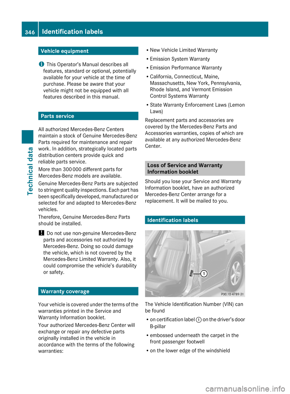
Identification labels
The Vehicle Identification Number (VIN) can
be found
Ron certification label : on the driver’s door
B-pillar
Rembossed underneath the carpet in the
front passenger footwell
Ron the lower edge of the windshield
346Identification labelsTechnical data
212_AKB; 2; 41, en-USd2ureepe,Version: 2.11.8.12009-07-17T09:14:21+02:00 - Seite 346
Page 349 of 372
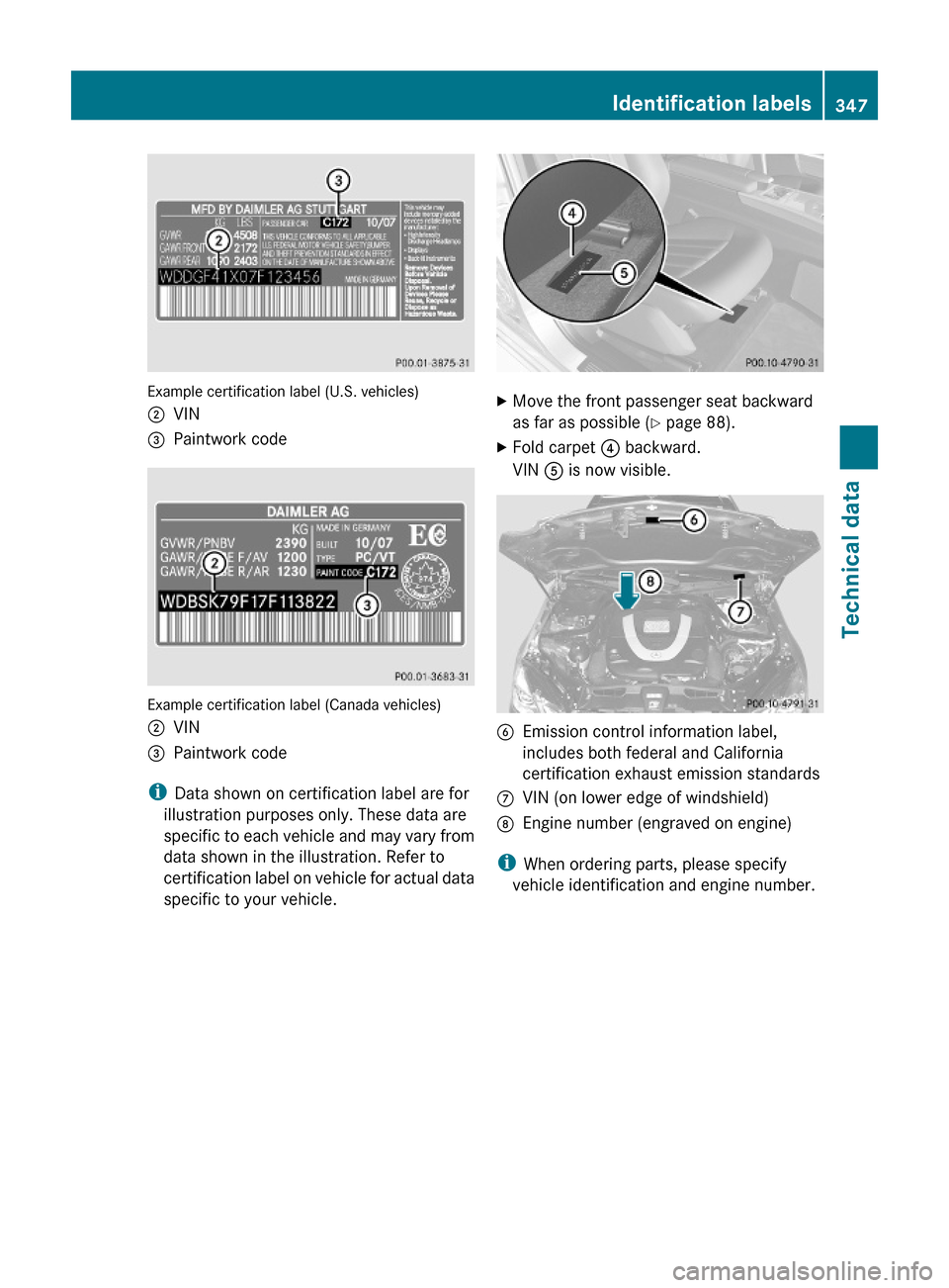
Example certification label (U.S. vehicles)
;VIN=Paintwork code
Example certification label (Canada vehicles)
;VIN=Paintwork code
iData shown on certification label are for
illustration purposes only. These data are
specific to each vehicle and may vary from
data shown in the illustration. Refer to
certification label on vehicle for actual data
specific to your vehicle.
XMove the front passenger seat backward
as far as possible (Y page 88).
XFold carpet ? backward.
VIN A is now visible.
BEmission control information label,
includes both federal and California
certification exhaust emission standards
CVIN (on lower edge of windshield)DEngine number (engraved on engine)
iWhen ordering parts, please specify
vehicle identification and engine number.
Identification labels347Technical data212_AKB; 2; 41, en-USd2ureepe,Version: 2.11.8.12009-07-17T09:14:21+02:00 - Seite 347Z
Page 350 of 372
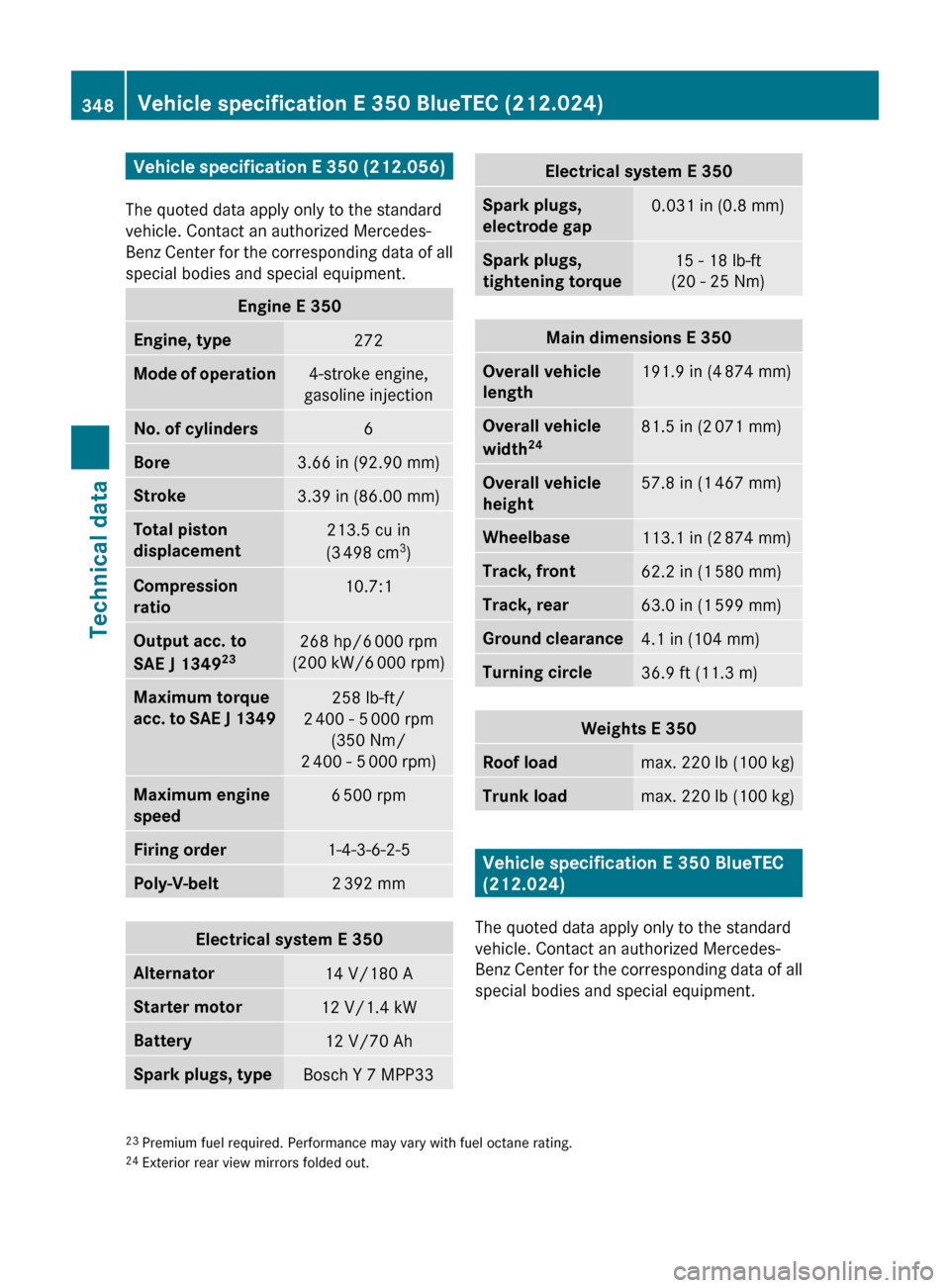
Vehicle specification E 350 (212.056)
The quoted data apply only to the standard
vehicle. Contact an authorized Mercedes-
Benz Center for the corresponding data of all
special bodies and special equipment.Engine E 350Engine, type272Mode of operation4-stroke engine,
gasoline injectionNo. of cylinders6Bore3.66 in (92.90 mm)Stroke3.39 in (86.00 mm)Total piston
displacement213.5 cu in
(3 498 cm 3
)Compression
ratio10.7:1Output acc. to
SAE J 1349 23268 hp/6
000 rpm
(200 kW/6 000 rpm)Maximum torque
acc. to SAE J 1349258 lb-ft/
2 400 - 5 000 rpm
(350 Nm/
2 400 - 5 000 rpm)Maximum engine
speed6 500 rpmFiring order1-4-3-6-2-5Poly-V-belt2 392 mmElectrical system E 350Alternator14 V/180 AStarter motor12 V/1.4 kWBattery12 V/70 AhSpark plugs, typeBosch Y 7 MPP33Electrical system E 350Spark plugs,
electrode gap0.031 in (0.8 mm)Spark plugs,
tightening torque15 - 18 lb-ft
(20 - 25 Nm)Main dimensions E 350Overall vehicle
length191.9 in (4 874 mm)Overall vehicle
width 2481.5 in (2
071 mm)Overall vehicle
height57.8 in (1 467 mm)Wheelbase113.1 in (2 874 mm)Track, front62.2 in (1 580 mm)Track, rear63.0 in (1 599 mm)Ground clearance4.1 in (104 mm)Turning circle36.9 ft (11.3 m)Weights E 350Roof loadmax. 220 lb (100 kg)Trunk loadmax. 220 lb (100 kg)
Vehicle specification E 350 BlueTEC
(212.024)
The quoted data apply only to the standard
vehicle. Contact an authorized Mercedes-
Benz Center for the corresponding data of all
special bodies and special equipment.
23 Premium fuel required. Performance may vary with fuel octane rating.
24 Exterior rear view mirrors folded out.348Vehicle specification E 350 BlueTEC (212.024)Technical data
212_AKB; 2; 41, en-USd2ureepe,Version: 2.11.8.12009-07-17T09:14:21+02:00 - Seite 348