steering MERCEDES-BENZ G-Class 2015 W463 Manual PDF
[x] Cancel search | Manufacturer: MERCEDES-BENZ, Model Year: 2015, Model line: G-Class, Model: MERCEDES-BENZ G-Class 2015 W463Pages: 350, PDF Size: 6.44 MB
Page 294 of 350
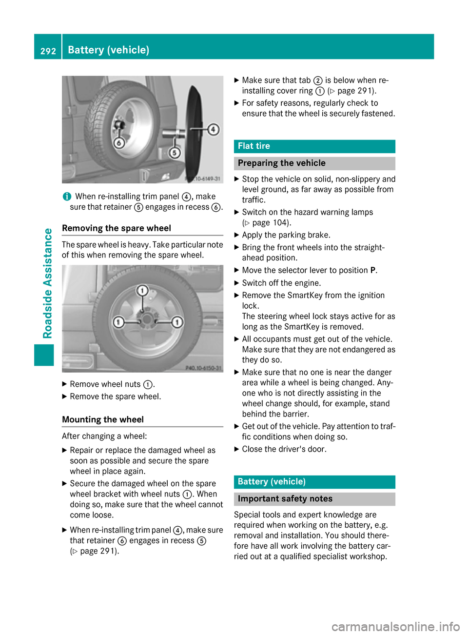
i
When re-installing trim panel
?, make
sure that retainer Aengages in recess B.
Removing the spare wheel The spare wheel is heavy. Take particular note
of this when removing the spare wheel. X
Remove wheel nuts :.
X Remove the spare wheel.
Mounting the wheel After changing a wheel:
X Repair or replace the damaged wheel as
soon as possible and secure the spare
wheel in place again.
X Secure the damaged wheel on the spare
wheel bracket with wheel nuts :. When
doing so, make sure that the wheel cannot
come loose.
X When re-installing trim panel ?, make sure
that retainer Bengages in recess A
(Y page 291). X
Make sure that tab ;is below when re-
installing cover ring :(Ypage 291).
X For safety reasons, regularly check to
ensure that the wheel is securely fastened. Flat tire
Preparing the vehicle
X Stop the vehicle on solid, non-slippery and
level ground, as far away as possible from
traffic.
X Switch on the hazard warning lamps
(Y page 104).
X Apply the parking brake.
X Bring the front wheels into the straight-
ahead position.
X Move the selector lever to position P.
X Switch off the engine.
X Remove the SmartKey from the ignition
lock.
The steering wheel lock stays active for as
long as the SmartKey is removed.
X All occupants must get out of the vehicle.
Make sure that they are not endangered as they do so.
X Make sure that no one is near the danger
area while a wheel is being changed. Any-
one who is not directly assisting in the
wheel change should, for example, stand
behind the barrier.
X Get out of the vehicle. Pay attention to traf-
fic conditions when doing so.
X Close the driver's door. Battery (vehicle)
Important safety notes
Special tools and expert knowledge are
required when working on the battery, e.g.
removal and installation. You should there-
fore have all work involving the battery car-
ried out at a qualified specialist workshop. 292
Battery (vehicle)Roadside Assistance
Page 295 of 350
G
WARNING
Work carried out incorrectly on the battery
can lead, for example, to a short circuit and
thus damage the vehicle electronics. This can lead to function restrictions applying to
safety-relevant systems, e.g. the lighting sys-
tem, ABS (anti-lock braking system) or ESP ®
(Electronic Stability Program). The operating
safety of your vehicle may be restricted. You
could lose control of the vehicle, for example:
R braking
R in the event of abrupt steering maneuver
and/or when the vehicle's speed is not
adapted to the road conditions
There is a risk of an accident.
In the event of a short circuit or a similar inci- dent, contact a qualified specialist workshop
immediately. Do not drive any further. You
should have all work involving the battery car-
ried out at a qualified specialist workshop.
If ABS malfunctions, the wheels can lock dur-
ing braking. This limits the steerability of the
vehicle when braking and may increase the
braking distance.
If ESP ®
malfunctions, the vehicle will not be
stabilized if it starts to skid or a wheel starts to spin.
i For further information about ABS and
ESP ®
, see (Y page 62) and (Y page 63). G
WARNING
During the charging process, a battery produ- ces hydrogen gas. If a short circuit occurs or
sparks are created, the hydrogen gas can
ignite. There is a risk of an explosion.
R Make sure that the positive terminal of a
connected battery does not come into con- tact with vehicle parts.
R Never place metal objects or tools on a bat-
tery.
R It is important that you observe the descri-
bed order of the battery terminals when
connecting and disconnecting a battery. R
When jump-starting, make sure that the
battery poles with identical polarity are
connected.
R It is particularly important to observe the
described order when connecting and dis-
connecting the jumper cables.
R Never connect or disconnect the battery
terminals while the engine is running. G
WARNING
Electrostatic build-up can lead to the creation of sparks, which could ignite the highly explo-
sive gases of a battery. There is a risk of an
explosion.
Before handling the battery, touch the vehicle body to remove any existing electrostatic
build-up.
The highly flammable gas mixture forms when
charging the battery as well as when jump-
starting.
Always make sure that neither you nor the
battery is electrostatically charged. A build-
up of electrostatic charge can be caused, for
example:
R by wearing clothing made from synthetic
fibers
R due to friction between clothing and seats
R if you push or pull the battery across the
carpet or other synthetic materials
R if you wipe the battery with a cloth G
WARNING
Battery acid is caustic. There is a risk of injury. Avoid contact with skin, eyes or clothing. Do
not inhale any battery gases. Do not lean over
the battery. Keep children away from batter-
ies. Wash away battery acid immediately with
plenty of clean water and seek medical atten- tion.
! Have the battery checked regularly at a
qualified specialist workshop.
Observe the service intervals in the Main-
tenance Booklet or contact a qualified spe- cialist workshop for more information. Battery (vehicle)
293Roadside Assistance Z
Page 300 of 350
The jump-starting connection point consists of poles
;and =.
X Lift up cover :of positive terminal ;in the direction of the arrow.
X Connect positive terminal ;on your vehicle to positive terminal ?of donor battery B
using the jumper cable. beginning with your own battery.
X Start the engine of the donor vehicle and run it at idling speed.
X Connect negative terminal Aof donor battery Bto ground point =of your vehicle using
the jumper cable, connecting the jumper cable to donor battery Bfirst.
X Start the engine.
X First, remove the jumper cables from ground point =and negative terminal A, then from
positive clamp ;and positive terminal ?. Each time beginning with your vehicle's battery.
X Have the battery checked at a qualified specialist workshop.
i Jump-starting is not considered to be a normal operating condition.
i Jumper cables and further information regarding jump-starting can be obtained at any
qualified specialist workshop. Towing and tow-starting
Important safety notes
G
WARNING
Functions relevant to safety are restricted or
no longer available if:
R the engine is not running.
R the brake system or the power steering is
malfunctioning.
R there is a malfunction in the voltage supply
or the vehicle's electrical system.
If your vehicle is being towed, much more
force may be necessary to steer or brake.
There is a risk of an accident.
In such cases, use a tow bar. Before towing,
make sure that the steering moves freely. G
WARNING
When towing or tow-starting another vehicle
and its weight is greater than the permissible gross weight of your vehicle, the:
R the towing eye could detach itself
R the vehicle/trailer combination could roll-
over.
There is a risk of an accident. When towing or tow-starting another vehicle,
its weight should not be greater than the per- missible gross weight of your vehicle.
! If DISTRONIC PLUS or the HOLD function
is activated, the vehicle brakes automati-
cally in certain situations. To prevent dam-
age to the vehicle, deactivate DISTRONIC
PLUS and the HOLD function in the follow- ing or other similar situations:
R when towing the vehicle
R in the car wash
! The vehicle can be towed a maximum of
30 miles (50km). The towing speed of
30 mph (50 km/h) must not be exceeded.
If the vehicle has to be towed more than
30 miles (50km), the entire vehicle must be
raised and transported.
! Only secure the tow cable or tow bar to
the towing eyes. You could otherwise dam- age the vehicle.
! Do not tow with sling-type equipment.
This could damage the vehicle.
! Do not use the towing eyes for recovery
purposes as this could damage the vehicle.
If in doubt, recover the vehicle with a crane. 298
Towing and tow-startingRoadside Assistance
Page 302 of 350
switch, the hazard warning lamps start
flashing again.
X Turn the SmartKey to position 2in the igni-
tion lock (Y page 133).
X When the vehicle is stationary, depress the
brake pedal and keep it depressed.
X Shift the transfer case to neu-
tral(Y page 188).
X Shift the automatic transmission to posi-
tion N.
X Release the brake pedal.
X Release the parking brake (Y page 151).
i The transmission can only change gear if
the battery has sufficient charge.
If you cannot move the selector lever to N,
the propeller shafts to the driven axles
must be removed. Transporting the vehicle
! You may only secure the vehicle by the
wheels, not by parts of the vehicle such as
axle or steering components. Otherwise,
the vehicle could be damaged.
Use the towing eyes to pull the vehicle if it
needs to be transported on a trailer or trans-
porter (Y page 299).
X Apply the parking brake.
X Turn the SmartKey to position 2in the igni-
tion lock (Y page 133).
X Move the selector lever to N.
X Shift the transfer case to neutral
(Y page 188).
X Secure the towing cable to the towing eyes
(Y page 299).
X Make sure that the vehicle cannot roll
away.
X Release the parking brake.
X Load the vehicle onto the transporter. As soon as the vehicle has been loaded:
X Apply the parking brake.
X Shift the automatic transmission to posi-
tion P.
X Turn the SmartKey to position 0in the igni-
tion lock (Y page 133) and remove it.
X Secure the vehicle. Recovering a vehicle that has become
stuck
! When recovering a vehicle that has
become stuck, pull it as smoothly and
evenly as possible. Excessive tractive
power could damage the vehicles.
If the drive wheels have become stuck in
loose or muddy ground, pull the vehicle out
with extreme caution, especially so if the vehi-
cle is loaded.
Never attempt to recover a stuck vehicle with
a trailer attached.
Pull out the vehicle backwards, if possible
using the tracks it made when it became
stuck. Towing in the event of malfunctions
General notes !
If you are removing the propeller shaft,
use M10 nuts as spacers on the M8 bolts
and secure them with M8 nuts.
New self-locking nuts must be used when
the propeller shafts are refitted.
X Observe the safety notes as you do so
(Y page 298).
i Consult an authorized Mercedes-Benz
Center. 300
Towing and tow-startingRoadside Assistance
Page 309 of 350
Regular checking of wheels and tires
G
WARNING
Damaged tires can cause tire inflation pres-
sure loss. As a result, you could lose control of your vehicle. There is a risk of accident.
Check the tires regularly for signs of damage
and replace any damaged tires immediately.
R Regularly check the wheels and tires of
your vehicle for damage at least once a
month, as well as after driving off-road or
on rough roads. Damage includes bulges
and deformation on tires, cuts, punctures,
cracks or severe corrosion on wheels, for
example. Damaged wheels can cause a
loss of tire pressure.
R Regularly check the tire tread depth and
the condition of the tread across the whole
width of the tire (Y page 307). In order to
inspect the inner side of the tire surface,
turn the steering wheel to full lock.
R All wheels must have a valve cap to protect
the valve against dirt and moisture. Do notinstall anything onto the valve other than
the standard valve cap or a valve cap
approved by Mercedes-Benz for your vehi-
cle.
Do not install anything onto the valve, such as tire pressure monitoring systems.
R You should regularly check the pressure of
all your tires including the spare wheel, par- ticularly prior to long trips. Adjust the tire
pressure as necessary (Y page 314).
The service life of tires depends, among other things, on the following factors:
R Driving style
R Tire pressure
R Distance covered Tire tread
G
WARNING
Insufficient tire tread will reduce tire traction.
The tire is no longer able to dissipate water. This means that on wet road surfaces, the risk
of hydroplaning increases, in particular where speed is not adapted to suit the driving con-
ditions. There is a risk of accident.
If the tire pressure is too high or too low, tires
may exhibit different levels of wear at differ-
ent locations on the tire tread. Thus, you
should regularly check the tread depth and
the condition of the tread across the entire
width of all tires.
Minimum tire tread depth for:
R Summer tires: âin (3 mm)
R M+S tires: ãin (4 mm)
For safety reasons, replace the tires before
the legally prescribed limit for the minimum
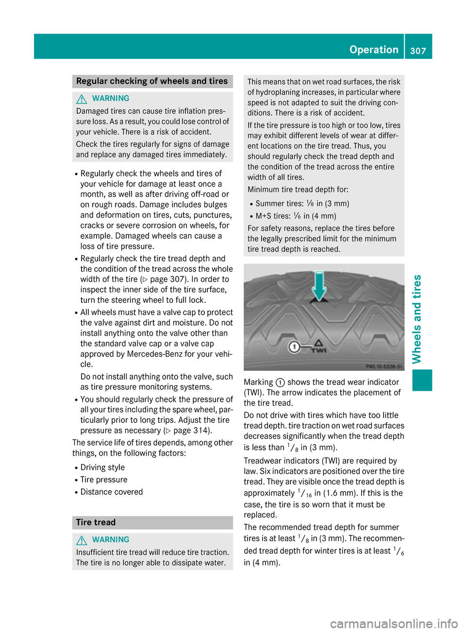
tire tread depth is reached. Marking
:shows the tread wear indicator
(TWI). The arrow indicates the placement of
the tire tread.
Do not drive with tires which have too little
tread depth. tire traction on wet road surfaces decreases significantly when the tread depth
is less than 1
/ 8 in (3 mm).
Treadwear indicators (TWI) are required by
law. Six indicators are positioned over the tire
tread. They are visible once the tread depth is
approximately 1
/ 16 in (1.6 mm). If this is the
case, the tire is so worn that it must be
replaced.
The recommended tread depth for summer
tires is at least 1
/ 8 in (3 mm). The recommen-
ded tread depth for winter tires is at least 1
/ 6
in (4 mm). Operation
307Wheels and tires Z
Page 315 of 350
Tire pressure monitor
Important safety notes G
WARNING
Each tire, including the spare (if provided),
should be checked at least once a month
when cold and inflated to the pressure rec-
ommended by the vehicle manufacturer on
the Tire and Loading Information placard on
the driver's door B-pillar or the tire pressure
label on the inside of the fuel filler flap. If your vehicle has tires of a different size than the
size indicated on the Tire and Loading Infor-
mation placard or the tire pressure label, you should determine the proper tire pressure for
those tires.
As an added safety feature, your vehicle has
been equipped with a tire pressure monitoring system (TPMS) that illuminates a low tire pres-
sure telltale when one or more of your tires
are significantly underinflated. Accordingly,
when the low tire pressure telltale illuminates,
you should stop and check your tires as soon
as possible, and inflate them to the proper
pressure. Driving on a significantly underin-
flated tire causes the tire to overheat and can lead to tire failure. Underinflation also
reduces fuel efficiency and tire tread life, andmay affect the vehicle's handling and stop-
ping ability.
Please note that the TPMS is not a substitute
for proper tire maintenance, and it is the driv-
er's responsibility to maintain correct tire
pressure, even if underinflation has not
reached the level to trigger illumination of the
TPMS low tire pressure telltale.
USA only:
Your vehicle has also been equipped with a
TPMS malfunction indicator to indicate if the
system is not operating properly. The TPMS
malfunction indicator is combined with the
low tire pressure telltale. When the system
detects a malfunction, the warning lamp will
flash for approximately a minute and then
remain continuously illuminated. This
sequence will be repeated every time the vehi- cle is started as long as the malfunction
exists.
When the malfunction indicator is illuminated,
the system may not be able to detect or signal
low tire pressure as intended. TPMS malfunc- tions may occur for a variety of reasons,
including the mounting of incompatible
replacement or alternate tires or wheels on
the vehicle that prevent the TPMS from func-
tioning properly. Always check the TPMS mal-
function telltale after replacing one or more
tires or wheels on your vehicle to ensure that
the replacement or alternate tires and wheels allow the TPMS to continue to function prop-
erly.
It is the driver's responsibility to set the tire
pressure to the recommended cold tire pres-
sure suitable for the operating situation
(Y page 309). Note that the correct tire pres-
sure for the current operating situation must
first be taught-in to the tire pressure monitor. If there is a substantial loss of pressure, the
warning threshold for the warning message is aligned to the reference values taught-in.
Restart the tire pressure monitor after adjust-
ing to the cold tire pressure (Y page 315).
The current pressures are saved as new ref-
erence values. As a result, a warning message will appear if the tire pressure drops signifi-
cantly.
The tire pressure monitor does not warn you
of an incorrectly set tire pressure. Observe
the notes on the recommended tire pressure
(Y page 309).
The tire pressure monitor is not able to warn
you of a sudden loss of pressure, e.g. if the
tire is penetrated by a foreign object. In the
event of a sudden loss of pressure, bring the
vehicle to a halt by braking carefully. Avoid
sudden steering movements.
In order to check the tire pressure, the vehi-
cle's wheels are installed with sensors that
monitor the tire pressure in all four tires. The tire pressure monitor warns you if the pres-
sure drops in one or more of the tires. The tire Tire pressure
313Wheels and tires Z
Page 318 of 350
If you wish to cancel the restart:
X Press the %button.
The tire pressure values stored at the last
restart will continue to be monitored. Loading the vehicle
Instruction labels for tires and loads
G
WARNING
Overloaded tires can overheat, causing a
blowout. Overloaded tires can also impair the steering and driving characteristics and lead
to brake failure. There is a risk of accident.
Observe the load rating of the tires. The load
rating must be at least half of the GAWR of
your vehicle. Never overload the tires by
exceeding the maximum load. :
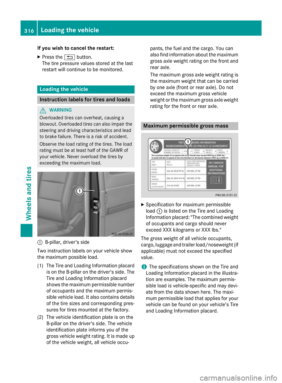
B-pillar, driver's side
Two instruction labels on your vehicle show
the maximum possible load.
(1) The Tire and Loading Information placard is on the B-pillar on the driver's side. The
Tire and Loading Information placard
shows the maximum permissible number
of occupants and the maximum permis-
sible vehicle load. It also contains details
of the tire sizes and corresponding pres-
sures for tires mounted at the factory.
(2) The vehicle identification plate is on the B-pillar on the driver's side. The vehicle
identification plate informs you of the
gross vehicle weight rating. It is made up
of the vehicle weight, all vehicle occu- pants, the fuel and the cargo. You can
also find information about the maximum gross axle weight rating on the front and
rear axle.
The maximum gross axle weight rating is the maximum weight that can be carried
by one axle (front or rear axle). Do not
exceed the maximum gross vehicle
weight or the maximum gross axle weight
rating for the front or rear axle. Maximum permissible gross mass
X
Specification for maximum permissible
load :is listed on the Tire and Loading
Information placard: "The combined weight of occupants and cargo should never
exceed XXX kilograms or XXX lbs."
The gross weight of all vehicle occupants,
cargo, luggage and trailer load/noseweight (if
applicable) must not exceed the specified
value.
i The specifications shown on the Tire and
Loading Information placard in the illustra- tion are examples. The maximum permis-
sible load is vehicle-specific and may devi-
ate from the data shown here. The maxi-
mum permissible load that applies for your vehicle can be found on your vehicle's Tire
and Loading Information placard. 316
Loading the vehicleWheels and ti
res