key battery MERCEDES-BENZ G500 2002 W463 Owner's Manual
[x] Cancel search | Manufacturer: MERCEDES-BENZ, Model Year: 2002, Model line: G500, Model: MERCEDES-BENZ G500 2002 W463Pages: 385, PDF Size: 30.37 MB
Page 7 of 385

4 Contents
Instrument cluster displayMalfunction and indicator
lamps in the
instrument cluster ....................264
On-board diagnostic system .........265
Check engine malfunction
indicator lamp .............................265
Brake warning lamp ..................266
Supplemental restraint system
(SRS) indicator lamp ..................267
Fuel reserve warning .................268
ABS malfunction
indicator lamp .............................269
Electronic stability program
(ESP) — warning lamp ...............270
Seat belt nonusage
warning lamp .............................270
Malfunction and indicator lamp
in the center console ................ 271
AIRBAG OFF indicator lamp ..... 271Malfunction and warning
messages in the
multifunction display .............. 272
DISPLAY DEFECTIVE
(engine control unit) ................. 273
DISPLAY DEFECTIVE
(several systems) ....................... 273
BATTERY / ALTERNATOR ........274
ANTILOCK BRAKE SYSTEM .... 275
BRAKE ASSIST ............................276
BRAKE PAD WEAR .................... 277
BRAKE FLUID ............................ 277
PARKING BRAKE ....................... 278
SEAT BELT SYSTEM .................. 278
ELEC. STABIL. PROG.
(Electronic stability program) . 279
COOLANT
(coolant level) ............................. 280
COOLANT
(coolant temperature) ............... 281
ENGINE OIL LEVEL ................... 282LIGHTING SYSTEM ....................283
LIGHT SENSOR ...........................285
DOOR ...........................................285
TRUNK OPEN .............................286
HOOD ...........................................286
TELEPHONE – FUNCTION .......287
TELE AID .....................................287
WASHER FLUID .........................288
RESTRAINT SYSTEM .................289
KEY ...............................................289
FUEL RESERVE ..........................290
UNDERVOLTAGE ........................290
ELECTRONIC BRAKE BOOSTER
(EBB) ............................................ 291
ENGINE AIR FILTER .................. 291
TC SHIFT ....................................292
TC SHIFT CONDITIONS ............292
TC IN NEUTRAL .........................293
TRANSFER CASE .......................293
J_G463.book Seite 4 Mittwoch, 19. September 2001 8:06 08
Page 8 of 385

5 Contents
Practical hintsFirst aid kit, vehicle tools
and jack ......................................296
CD-changer .....................................296
Fuses ................................................297
Electrical outlet .............................. 301
Stowing items in the vehicle ........ 301
Hood .................................................302
Checking engine oil level .............304
Automatic transmission
fluid level ...................................305
Engine oil consumption ................305
Coolant level ...................................306
Adding coolant ...........................306
Windshield washer/headlamp
cleaning system .........................307
Windshield and headlamp
washer fluid mixing ratio .........307Vehicle jack .................................... 308
Wheels ............................................. 310
Tire replacement ........................ 310
Rotating wheels .......................... 311
Spare wheel cover ..........................312
Spare wheel ..................................... 313
Changing wheels ............................ 314
Tire inflation pressure .................. 318
Battery .............................................. 319
Jump starting ................................. 321
Towing the vehicle ........................ 324
Transmission selector lever,
manually unlocking .................. 327
Stranded vehicle ............................ 327
Exterior lamps ............................... 328
Headlamp assembly .................. 329
Fog lamp, front ........................... 332
Turn signal lamp, front ............ 334Turn signal lamp, side ...............335
Front and rear
side marker lamps .....................337
Taillamp assemblies ..................339
License plate lamp .....................340
Rear fog lamp / Backup lamp ... 341
Changing batteries in
the electronic key .....................343
Synchronizing
remote control ............................345
Emergency operation of
sliding/pop-up roof ...................346
Manual release for
fuel filler flap .............................347
Replacing wiper blades .................348
J_G463.book Seite 5 Mittwoch, 19. September 2001 8:06 08
Page 31 of 385
28 Central locking system
Te ch n i c a l
data Instruments
and controlsOperationDrivingInstrument
cluster displayPractical hints Car care Index
Start lock-out
Important!
Removing the electronic key from the starter switch
activates the start lock-out. The engine cannot be
started.
Inserting the electronic key in the starter switch
deactivates the start lock-out.
Note:
In case the engine cannot be started (vehicle’s battery is
in order), the system is not operational. Contact an
authorized Mercedes-Benz Light Truck Center or call
1-800-FOR-MERCedes (in the USA), or 1-800-387-0100
(in Canada).General notes on the central locking system
If the electronic key is inserted in the starter switch, the
vehicle cannot be locked or unlocked with the remote
control.
If the vehicle cannot be locked or unlocked:
•Check the batteries of the electronic key, see
page 343, or synchronize the electronic key, see
page 345.
•Use the mechanical key to unlock the vehicle. To
start engine, insert the electronic key in the starter
switch. There could be a slight delay until the
electronic key can be turned in the starter switch.
Important!
When unlocking the driver’s door with the mechanical
key, the exterior lamps will flash and the alarm will
sound.
To cancel the alarm, insert the electronic key in the
starter switch or press buttonŒ or‹ on the
electronic key.
J_G463.book Seite 28 Mittwoch, 19. September 2001 8:06 08
Page 32 of 385
29 Central locking system
Te ch n i c a l
data Instruments
and controlsOperationDrivingInstrument
cluster displayPractical hints Car care Index Central locking system
Radio frequency and infrared remote control
The electronic key has an integrated radio frequency
and infrared remote control.
Due to the extended operational range of the remote
control, it could be possible to unintentionally lock or
unlock the vehicle by pressing the transmit button. If
one of the transmit buttons is pressed, the battery check
lamp lights up briefly – indicating that the batteries are
in order. See page 343 for checking batteries.
The vehicle doors, tailgate and fuel filler flap can be
centrally locked and unlocked via remote control.
Opening and closing the windows can only be done with
the infrared portion of the remote control. Aim
transmitter eye at the receiver of the driver’s door (6),
press and hold transmit button Œ or ‹,
seepage32.
If the electronic key is inserted in the starter switch, the
vehicle cannot be locked or unlocked with the remote
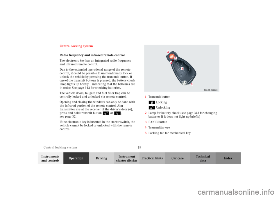
control.1Transmit button
‹ Locking
ΠUnlocking
2Lamp for battery check (see page 343 for changing
batteries if it does not light up briefly)
3PANIC button
4Transmitter eye
5Locking tab for mechanical key
P80.35-2033-26
2
1
4
3
5
J_G463.book Seite 29 Mittwoch, 19. September 2001 8:06 08
Page 34 of 385
31 Central locking system
Te ch n i c a l
data Instruments
and controlsOperationDrivingInstrument
cluster displayPractical hints Car care Index Locking and unlocking with remote control
Unlocking:
Press transmit button Œ. All turn signal lamps blink
once to indicate that the vehicle is unlocked.
The remote control can be programmed for two kinds of
unlocking modes (see below):
Selective unlocking mode –
Press transmit button Œ once to unlock driver’s door
and fuel filler flap.
Press transmit button Πtwice to unlock all doors,
fuel filler flap, and tailgate.
Global unlocking mode –
Press transmit button Πonce to unlock all doors,
fuel filler flap, and tailgate.
Notes:
If the tailgate was previously locked separately, it will
remain locked, see page 39.
The presently active unlocking mode (selective or
global) can only be determined by unlocking the vehicle
with the remote control (see below for changing mode).If within 40 seconds of unlocking with the remote
control, neither door or tailgate is opened, the electronic
key is not inserted in the starter switch, or the central
locking switch is not activated, the vehicle will
automatically lock.
Locking:
Press transmit button ‹ once. All turn signal lamps
blink three times to indicate that the vehicle is locked. If
they do not blink three times, a door or the tailgate is
not properly closed.
Note:
If the vehicle cannot be locked or unlocked by pressing
the transmit button, then it may be necessary to change
the batteries in the electronic key (if ok, battery check
lamp in electronic key will light briefly when pressing
transmit button) or to synchronize the remote control,
see pages 343 and 345.
Choosing global or selective mode on remote control
Press and hold transmit buttons‹ andŒ
simultaneously for 6 seconds to reprogram the remote
control. Battery check lamp will blink two times
indicating the completed mode change.
J_G463.book Seite 31 Mittwoch, 19. September 2001 8:06 08
Page 35 of 385
32 Central locking system
Te ch n i c a l
data Instruments
and controlsOperationDrivingInstrument
cluster displayPractical hints Car care Index
Opening and closing windows and sliding / pop-up
roof from outside
(summer opening / convenience feature)
Aim transmitter eye of remote control at the driver’s
door receiver.
Summer opening:
The sliding / pop-up roof and all side windows can be
opened automatically.
Continue to press transmit button Πafter unlocking
the vehicle.
The windows and sliding/pop-up roof begin to open
after approximately 1 second.
To interrupt opening procedure, release transmit
button.
Convenience feature:
The sliding / pop-up roof and the side windows can be
closed.
Continue to press transmit button ‹ after locking
the vehicle.
The windows and sliding / pop-up roof begin to close
after approximately 1 second.To interrupt closing procedure, release transmit button.
Ensure that all side windows and the sliding / pop-up
roof are properly closed before leaving the vehicle.
Note:
If the windows and sliding / pop-up roof cannot be
operated automatically by pressing the transmit button
of t he r emo te c ontr ol then it m ay be n ece ssar y to chan ge
the batteries in the electronic key (if ok, battery check
lamp in electronic key will light briefly when
transmitting), or to synchronize the remote control, see
page 343 and 345.
Wa r n i n g !
Never operate the windows or sliding / pop-up roof
if there is the possibility of anyone being harmed
by the opening or closing procedure.In case the procedure causes potential danger, the
procedure can be immediately halted by releasing
the remote control button. To reverse direction of
movement press Œ for opening or ‹ for
closing.
J_G463.book Seite 32 Mittwoch, 19. September 2001 8:06 08
Page 50 of 385
47 Seats
Te ch n i c a l
data Instruments
and controlsOperationDrivingInstrument
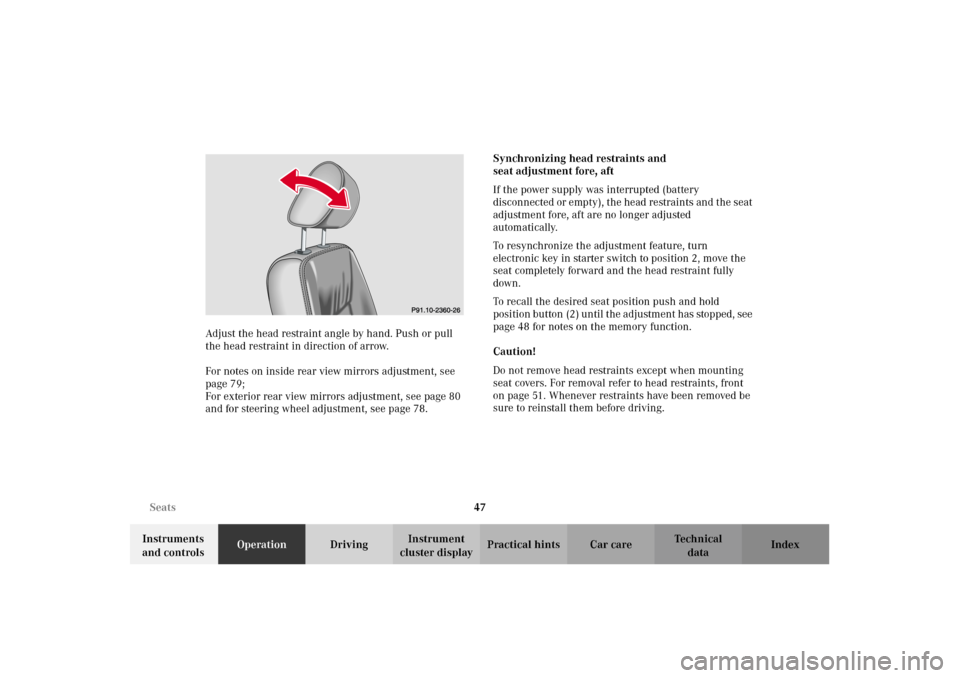
cluster displayPractical hints Car care Index Adjust the head restraint angle by hand. Push or pull
the head restraint in direction of arrow.
For notes on inside rear view mirrors adjustment, see
page 79;
For exterior rear view mirrors adjustment, see page 80
and for steering wheel adjustment, see page 78.Synchronizing head restraints and
seat adjustment fore, aft
If the power supply was interrupted (battery
disconnected or empty), the head restraints and the seat
adjustment fore, aft are no longer adjusted
automatically.
To resynchronize the adjustment feature, turn
electronic key in starter switch to position 2, move the
seat completely forward and the head restraint fully
down.
To recall the desired seat position push and hold
position button (2 ) un til t he ad justm ent has stop ped , see
page 48 for notes on the memory function.
Caution!
Do not remove head restraints except when mounting
seat covers. For removal refer to head restraints, front
on page 51. Whenever restraints have been removed be
sure to reinstall them before driving.
P91.10-2360-26
J_G463.book Seite 47 Mittwoch, 19. September 2001 8:06 08
Page 128 of 385
125 Flexible service system
Te ch n i c a l
data Instruments
and controlsOperationDrivingInstrument
cluster displayPractical hints Car care Index The next service due date is displayed either in days or
in miles, depending on your driving style.
Once the suggested service term has passed, the symbol
and message appear for approximately 30 seconds and
a signal sounds every time when turning the electronic
key in starter switch to position 2.
The service indicator disappears automatically after
30 seconds or if the knob for instrument cluster
illumination, see page 84, in the instrument cluster is
pressed.
Calling up service indicator manually:
Turn the electronic key in starter switch to position 1
or 2.
Call up the trip odometer and main odometer by
pressing button è or ÿ on the multifunction
steering wheel until the display appears. See page 94.
Press button j or k until the FSS indicator
appears.
The next or previous system is displayed by pressing
button è or ÿ.Important!
The FSS indicator is not an engine oil level indicator.
See page 127 for engine oil level indicator.
Note:
When disconnecting vehicle battery for one or more
days at a time, such days will not be counted. Any such
days not counted by the FSS can be added by your
Mercedes-Benz Light Truck Center.
The interval between services is determined by the type
of driving for which the vehicle is used. For example,
driving at extreme speeds, and cold starts combined
wit h short distan ce d r iving in which the e ngin e d oes not
reach operating normal temperature, reduce the interval
between services.
J_G463.book Seite 125 Mittwoch, 19. September 2001 8:06 08
Page 151 of 385
148 Climate control
Te ch n i c a l
data Instruments
and controlsOperationDrivingInstrument
cluster displayPractical hints Car care Index
Residual engine heat utilization
With the engine switched off, it is possible to continue
to heat or ventilate the interior for a short while,
dependent of the temperature setting of the climate
control. Air volume and distribution are controlled
automatically.
To select:
Turn the electronic key in starter switch to position 1
or 0 or remove it altogether.
Press button T. The indicator lamp in the button
illuminates.
Set the left and right temperature to your personal
requirements.
This function selection will not activate if the battery
level is insufficient. Press button T again to switch off. The indicator
lamp in the button will go out.
The function switches off automatically:
•if the electronic key in starter switch is turned to
position 2,
•after approximately 30 minutes,
•if the battery voltage drops.
J_G463.book Seite 148 Mittwoch, 19. September 2001 8:06 08
Page 152 of 385
149 Climate control
Te ch n i c a l
data Instruments
and controlsOperationDrivingInstrument
cluster displayPractical hints Car care Index Rear window defroster
Turn the electronic key in starter switch to position 2.
To select:
Press the F button in the control panel of the
automatic air conditioner. The indicator lamp in the
button illuminates.
To c a nc el:
Press the F button in the control panel of the
automatic air conditioner. The indicator lamp in the
button goes out.Notes:
Heavy accumulation of snow and ice should be removed
before activating the defroster.
The rear window defroster uses a large amount of power.
To keep the battery drain to a minimum, turn off the
defroster as soon as the rear window is clear.
The defroster is automatically turned off after
approximately 6–17 minutes of operation depending on
the outside temperature and vehicle speed.
If several power consumers are turned on
simultaneously, or the battery is only partially charged,
it is possible that the defroster will automatically turn
itself off. When this happens, the indicator lamp inside
the switch starts blinking.
As soon as the battery has sufficient voltage, the
defroster automatically turns itself back on.
J_G463.book Seite 149 Mittwoch, 19. September 2001 8:06 08