power steering MERCEDES-BENZ G500 2002 W463 Owner's Manual
[x] Cancel search | Manufacturer: MERCEDES-BENZ, Model Year: 2002, Model line: G500, Model: MERCEDES-BENZ G500 2002 W463Pages: 385, PDF Size: 30.37 MB
Page 5 of 385

2 Contents
Infant and
child restraint systems ................ 73
Steering wheel adjustment
(electrical) .................................... 78
Inside rear view mirror ................... 79
Antiglare night position .............. 79
Exterior rear view mirrors ............. 80
Instrument cluster ........................... 84
Multifunction steering wheel,
multifunction display ................. 90
Trip and main odometer and
sub menu ..................................... 94
Audio systems .................................. 96
Radio .............................................. 96
CD player ....................................... 97
Telephone .......................................... 98
Navigation system .......................... 103
Trip computer ................................. 104
Malfunction/warning
message memory ...................... 106
Individual settings ......................... 108
Setting the audio volume .............. 122
Coolant temperature gauge .......... 123Flexible service system
(FSS) ........................................... 124
Engine oil level indicator ............. 127
Exterior lamp switch ..................... 129
Headlamp mode ..............................130
Night security illumination ..........132
Locator lighting ...........................133
Headlamp cleaning system ...........133
Combination switch .......................134
Rear window wiper/washer ..........138
Hazard warning flasher switch ....139
Climate control .............................. 140
Rear passenger compartment
adjustable air outlets ................150
Power windows ............................... 151
Sliding/pop-up roof ........................154
Interior lighting ..............................156
Door entry lamps ........................157
Rear interior lamps ....................158
Cargo compartment lamps ........159
Sun visors ........................................ 161
Illuminated vanity mirrors ........... 161
Interior .............................................162Storage compartments,
armrest and cup holder ........... 162
Glove box ..................................... 163
Ashtrays .......................................... 168
Lighter ............................................. 170
Floor mat ......................................... 170
Split rear seat bench ..................... 171
Rear seat head restraints .......... 173
Enlarged cargo area ....................... 174
Cargo tie-down rings ..................... 174
Partition net .................................... 175
Loading instructions ..................... 178
Parcel net in
front passenger footwell .......... 180
Cargo area cover blind .................. 180
Roof racks ........................................ 181
Brush guard .................................... 182
Telephone, general ........................ 184
Cellular telephone ......................... 184
Garage door opener ....................... 185
J_G463.book Seite 2 Mittwoch, 19. September 2001 8:06 08
Page 9 of 385

6 Contents
Vehicle careCleaning and care
of the vehicle .............................350
Power washer .............................. 351
Tar stains ..................................... 351
Paintwork, painted body
components ................................. 351
Engine cleaning ..........................352
Vehicle washing .........................352
Ornamental moldings ................352
Headlamps, taillamps,
turn signal lenses ......................352
Window cleaning ........................353
Wiper blades ...............................353
Light alloy wheels ......................353
Instrument cluster .....................353
Steering wheel and
gear selector lever ......................353
Cup holder ...................................354
Seat belts .....................................354Headliner .................................... 354
Upholstery .................................. 354
Hard plastic trim items ............. 354
Plastic and rubber parts ........... 354
Technical dataSpare parts service ....................... 356
Warranty coverage ........................ 356
Identification labels ...................... 357
Layout of poly-V-belt drive ........... 358
Technical data ................................ 359
Fuels, coolants, lubricants etc. –
capacities ................................... 361
Engine oils ...................................... 363
Engine oil additives ...................... 363
Air conditioner refrigerant .......... 363
Brake fluid ...................................... 363
Premium unleaded gasoline ........ 364
Fuel requirements ........................ 364
Gasoline additives ......................... 365
Coolants .......................................... 365
Consumer information ................. 367
IndexIndex ................................................369
J_G463.book Seite 6 Mittwoch, 19. September 2001 8:06 08
Page 25 of 385
22 Instruments and controls
Te ch n i c a l
data Instruments
and controlsOperation DrivingInstrument
cluster displayPractical hints Car care Index
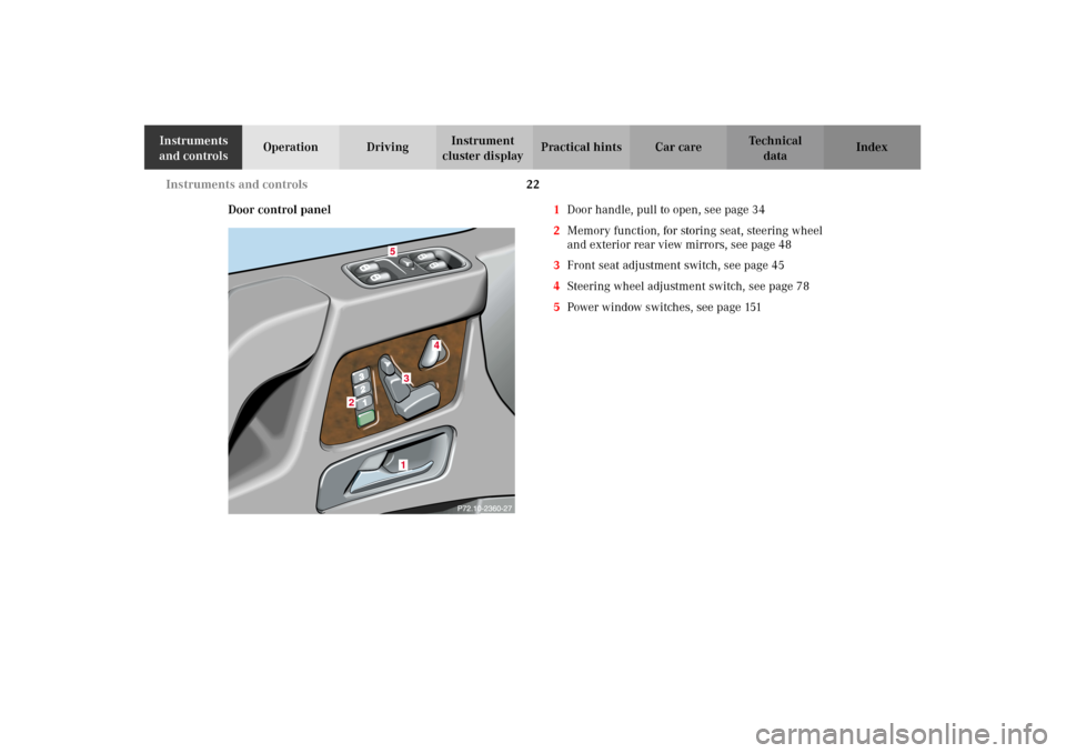
Door control panel1Door handle, pull to open, see page 34
2Memory function, for storing seat, steering wheel
and exterior rear view mirrors, see page 48
3Front seat adjustment switch, see page 45
4Steering wheel adjustment switch, see page 78
5Power window switches, see page 151
1
2
3
4
5
J_G463.book Seite 22 Mittwoch, 19. September 2001 8:06 08
Page 49 of 385
46 Seats
Te ch n i c a l
data Instruments
and controlsOperationDrivingInstrument
cluster displayPractical hints Car care Index
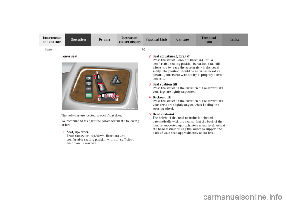
Power seat
The switches are located in each front door.
We recommend to adjust the power seat in the following
order:
1Seat, up / down
Press the switch (up / down direction) until
comfortable seating position with still sufficient
headroom is reached.2Seat adjustment, fore / aft
Press the switch (fore / aft direction) until a
comfortable seating position is reached that still
allows you to reach the accelerator / brake pedal
safely. The position should be as far rearward as
possible, consistent with ability to properly operate
controls.
3Seat cushion tilt
Press the switch in the direction of the arrow until
your legs are lightly supported.
4Backrest tilt
Press the switch in the direction of the arrow until
your arms are slightly angled when holding the
steering wheel.
5Head restraint
The height of the head restraint is adjusted
automatically with the seat so that the back of the
head is supported approximately at ear level. Adjust
the head restraint using the switch to support the
back of your head approximately at ear level.
5
41
3
2
2
J_G463.book Seite 46 Mittwoch, 19. September 2001 8:06 08
Page 50 of 385
47 Seats
Te ch n i c a l
data Instruments
and controlsOperationDrivingInstrument
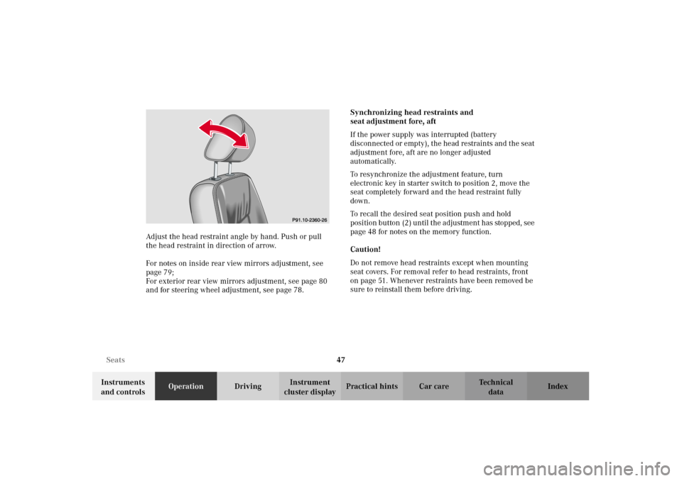
cluster displayPractical hints Car care Index Adjust the head restraint angle by hand. Push or pull
the head restraint in direction of arrow.
For notes on inside rear view mirrors adjustment, see
page 79;
For exterior rear view mirrors adjustment, see page 80
and for steering wheel adjustment, see page 78.Synchronizing head restraints and
seat adjustment fore, aft
If the power supply was interrupted (battery
disconnected or empty), the head restraints and the seat
adjustment fore, aft are no longer adjusted
automatically.
To resynchronize the adjustment feature, turn
electronic key in starter switch to position 2, move the
seat completely forward and the head restraint fully
down.
To recall the desired seat position push and hold
position button (2 ) un til t he ad justm ent has stop ped , see
page 48 for notes on the memory function.
Caution!
Do not remove head restraints except when mounting
seat covers. For removal refer to head restraints, front
on page 51. Whenever restraints have been removed be
sure to reinstall them before driving.
P91.10-2360-26
J_G463.book Seite 47 Mittwoch, 19. September 2001 8:06 08
Page 52 of 385
49 Seats
Te ch n i c a l
data Instruments
and controlsOperationDrivingInstrument
cluster displayPractical hints Car care Index Storing positions into memory:
With the electronic key in starter switch position 1 or 2
or with the relevant door open and the electronic key
inserted in the starter switch.
Adjust the seat to the desired position, see page 46.
Driver’s seat:
You can also adjust the steering wheel and the exterior
rear view mirrors electrically for the driver’s seat. See
page 80 for exterior rear view mirror adjustment and
page 78 for steering wheel adjustment.
Push memory button (1), release and push the position
button (2) within 3 seconds.Recalling positions from memory:
To recall a seat / steering wheel / exterior rear view
mirror position, push and hold button (2) to selected
memory position until the adjustment has stopped.
The seat / steering wheel / exterior rear view mirror
movement stops when the button is released.
Caution!
Do not operate the power seats using the memory
button if the backrest is in an excessively reclined
position. Doing so could cause damage to front or rear
seats.
First move backrest to an upright position.
J_G463.book Seite 49 Mittwoch, 19. September 2001 8:06 08
Page 220 of 385
217 Driving instructions
Te ch n i c a l
data Instruments
and controlsOperationDrivingInstrument
cluster displayPractical hints Car care Index Power assistance
BrakesExcessive use of road salt and other snow melting
chemicals spread on roads during the winter months
may cause a build up of moisture or residue to form on
the braking components. This build up or residue could
cause light corrosion of the braking components if the
vehicle is parked with the brakes cold. Apply steady and
even braking pressure when stopping the vehicle to
warm up and dry the brake components.
Important!
Please pay attention to the function of the brake assist
system (BAS), see page 237.
The condition of the parking brake system is checked
each time the vehicle is in the shop for the required
maintenance service.
If the parking brake is released and the brake warning
lamp in the instrument cluster stays on and there is no
audible warning (EBB), the brake fluid level in the
reservoir is too low.
Brake pad wear or a leak in the system may be the
reason for low brake fluid in the reservoir.
Have the brake system inspected at an authorized
Mercedes-Benz Light Truck Center immediately.
Wa r n i n g !
When the engine is not running, the brake and
steering systems are without power assistance.
Under these circumstances, a much greater effort is
necessary to stop or steer the vehicle.Wa r n i n g !
After driving in heavy rain for some time without
applying the brakes or through water deep enough
to wet brake components or salty road conditions,
the first braking action may be somewhat reduced
and increased pedal pressure may be necessary to
obtain expected braking effect. Be sure to maintain
a safe distance from vehicles in front.Resting your foot on the brake pedal will cause
excessive and premature wear of the brake pads.It can also result in the brakes overheating thereby
significantly reducing their effectiveness. It may
not be possible to stop the vehicle in sufficient time
to avoid an accident.
J_G463.book Seite 217 Mittwoch, 19. September 2001 8:06 08
Page 242 of 385
239 Driving systems
Te ch n i c a l
data Instruments
and controlsOperationDrivingInstrument
cluster displayPractical hints Car care Index Antilock brake system (ABS)
Important!
The ABS improves steering control of the vehicle during
hard braking maneuvers.
The ABS prevents the wheels from locking up above a
vehicle speed of approximately 5 mph (8 km / h)
independent of road surface conditions.
At the instant one of the wheels is about to lock up, a
slight pulsation can be felt in the brake pedal,
indicating that the ABS is in the regulating mode. Keep
firm and steady pressure on the brake pedal while
experiencing the pulsation.
Continuous steady brake pedal pressure results in
applying the advantages of the ABS, namely braking
power and ability to steer the vehicle.In the case of an emergency brake maneuver keep
continuous full pressure on the brake pedal. In this
manner only can the ABS be most effective.
On slippery road surfaces, the ABS will respond even
with light brake pedal pressure because of the
increased likelihood of locking wheels. The pulsating
brake pedal can be an indication of hazardous road
conditions and functions as a reminder to take extra
care while driving.
ABS control
The ABS malfunction indicator lamp- in the
instrument cluster comes on with the electronic key in
starter switch position 2 and should go out with the
engine running.
When the ABS malfunction indicator lamp- in the
instrument cluster comes on while the engine is
running, it indicates that the ABS has detected a
malf un ction an d has s witched of f . In t his c ase, t he brake
system functions in the usual manner, but without
antilock assistance.
With the ABS malfunctioning, the BAS, ESP and 4-ETS
are also switched off. The malfunction indicator lamps
come on with the engine running.
Wa r n i n g !
Do not pump the brake pedal, rather use firm,
steady brake pedal pressure. Pumping the brake
pedal defeats the purpose for ABS and significantly
reduces braking effectiveness.
J_G463.book Seite 239 Mittwoch, 19. September 2001 8:06 08
Page 247 of 385
244 Driving systems
Te ch n i c a l
data Instruments
and controlsOperationDrivingInstrument
cluster displayPractical hints Car care Index
If the ESP warning lampv comes on continuously
and warning messages appears in the multifunction
display with the engine running, a malfunction has
been detected in either system. Only partial engine
output will be available.
If the BAS malfunctions, the brake system functions in
the usual manner, but without BAS, ESP and 4-ETS.
If the ESP warning lampv and the
Émalfunction indicator lamp come on and warning
messages appears in the multifunction display, have the
BAS or ESP checked at your authorized Mercedes-Benz
Light Truck Center as soon as possible.
With the ABS malfunctioning, the BAS, ESP and 4-ETS
are also switched off.
For warn in g m ess ages and malfun ction in d icator lamps ,
see page 264 and page 272.
Driving the vehicle with varied size tires will cause the
wheels to rotate at different speeds, therefore the ESP
may activate (yellow ESP warning lampv in
speedometer dial comes on). For this reason, all wheels,
including the spare wheel, must have the same tire
outside diameter.When testing the parking brake on a brake test
dynamometer, the engine must be shut off. Otherwise,
the ESP will immediately be engaged and will apply the
rear wheel brakes.
In winter operation, the maximum effectiveness of the
ESP is on ly achieved wit h Me rced es -B enz re comm end ed
M+S rated radial-ply tires and / or snow chains.
Synchronizing ESP
If the power supply was interrupted (battery
disconnected or empty), the ESP warning lampv
and warning messages appears in the multifunction
display with the engine running.
Turn steering wheel completely to the left and then to
the right. The ESP warning lampv and the warning
messages in the multifunction display should go out.
J_G463.book Seite 244 Mittwoch, 19. September 2001 8:06 08
Page 254 of 385
251 Driving systems
Te ch n i c a l
data Instruments
and controlsOperationDrivingInstrument
cluster displayPractical hints Car care Index A few words about differentials and differential
locks
When a vehicle negotiates a turn, wheels on the outside
of the curve must travel farther and rotate faster than
the inside wheels. The differential, the operation of a set
of gears that allow the powered wheels in a vehicle to
turn a different speeds, provides for this essential
function.
The drawback is that the differential also sends most of
the engine's power to the wheel with the least load or
strain on it. For example, if one of a vehicle's powered
wheels sits on a patch of snow and spins because there
is no traction, all of the engine's power will go to that
wheel because the power will take the path of least
resistance. Meanwhile, the opposite wheel, sitting on
dry pavement where it could get enough grip to start the
vehicle moving, sits idle because it gets no power.
The Electronic Traction System (ETS) addresses this
problem and provides for good control and steering
ability by automatically slowing the slipping wheel and
thus increasing the power to the other non-slipping
d rive whee ls to get t he ve hicle m ovin g. The ESP and ETS
in this vehicle feature such intelligent limited-slip
differential technology, ideally suited for on-road and light off-road driving. The position “LOW” of the
transfer case (see pages 247and 226) also enhances
off-road driving capabilities.
More extreme off-road conditions may call for another
cure which is to engage a differential lock, preventing
the differential from operating altogether. This vehicle
offers as standard equipment three differential locks:
front, transfer case (center), and rear. Each can be
engaged simply by pushing a dashboard-mounted
button (see pages 253 and 254 for engaging differential
locks). When the transfer case (center) differential is
locked, half of the engine's power is automatically
distributed to the front wheels and half to the rear
wheels. When the rear differential is locked, power
going to the rear wheels is equally distributed, so that
both rear wheels turn at the same speed and torque.
When the front differential is locked, all four wheels
now turn with equal power and torque. Please be aware
that engaging the differential locks will significantly
reduce steering ability of the vehicle.
J_G463.book Seite 251 Mittwoch, 19. September 2001 8:06 08