height MERCEDES-BENZ G55AMG 2010 W463 User Guide
[x] Cancel search | Manufacturer: MERCEDES-BENZ, Model Year: 2010, Model line: G55AMG, Model: MERCEDES-BENZ G55AMG 2010 W463Pages: 272, PDF Size: 7.04 MB
Page 136 of 272

Keep compartment lids closed. This will help
to prevent stored objects from being thrown
about and injuring vehicle occupants during
Rbraking
Rvehicle maneuvers
Ran accident
Storage bags
GWarning!
Storage bags are intended for storing light-
weight items only.
Heavy objects, objects with sharp edges or
fragile objects may not be transported in the
storage bag. In an accident, during hard
braking, or sudden maneuvers, they could be
thrown around inside the vehicle and cause
injury to vehicle occupants.
Storage bags cannot protect transported
goods in the event of an accident.
Storage bags are located on the back of the
front seats.
Useful features
Cup holders
GWarning!
In order to help prevent spilling liquids on
vehicle occupants and/or vehicle equipment,
only use containers that fit into the cup
holder. Use lids on open containers and do
not fill containers to a height where the
contents, especially hot liquids, could spill
during braking, vehicle maneuvers, or in an
accident. Liquids spilled on vehicle occupants
may cause serious personal injury. Liquids
spilled on vehicle equipment may cause
damage not covered by the Mercedes-Benz
Limited Warranty.
When not in use, keep the cup holder closed.
An open cup holder may cause injury to you
or others when contacted during braking,
vehicle maneuvers, or in an accident.
Keep in mind that objects placed in the cup
holder may come loose during braking,
vehicle maneuvers, or in an accident and be
thrown around in the vehicle interior. Objects
thrown around in the vehicle interior may
cause an accident and/or serious personal
injury.
Cup holder next to armrest
XPlace bracket of cup holder : into recess
indicated by arrow of cup holder base ;.
If the cup holder is no longer in use, it can for
example, be stored in the glove box or storage
compartment below the armrest.
Cup holder in front passenger footwell
XSwing cup holder : upwards until it clicks
into place.
! Fold the cup holder closed before moving
the front passenger seat fully forward.
134Useful featuresControls in detail
463_AKB; 3; 35, en-USd2ureepe,Version: 2.11.8.12009-07-16T20:59:56+02:00 - Seite 134
Page 155 of 272
! Never open the hood if the wiper arms are
folded forward away from the windshield.
Otherwise the windshield wipers or the
hood could be damaged.
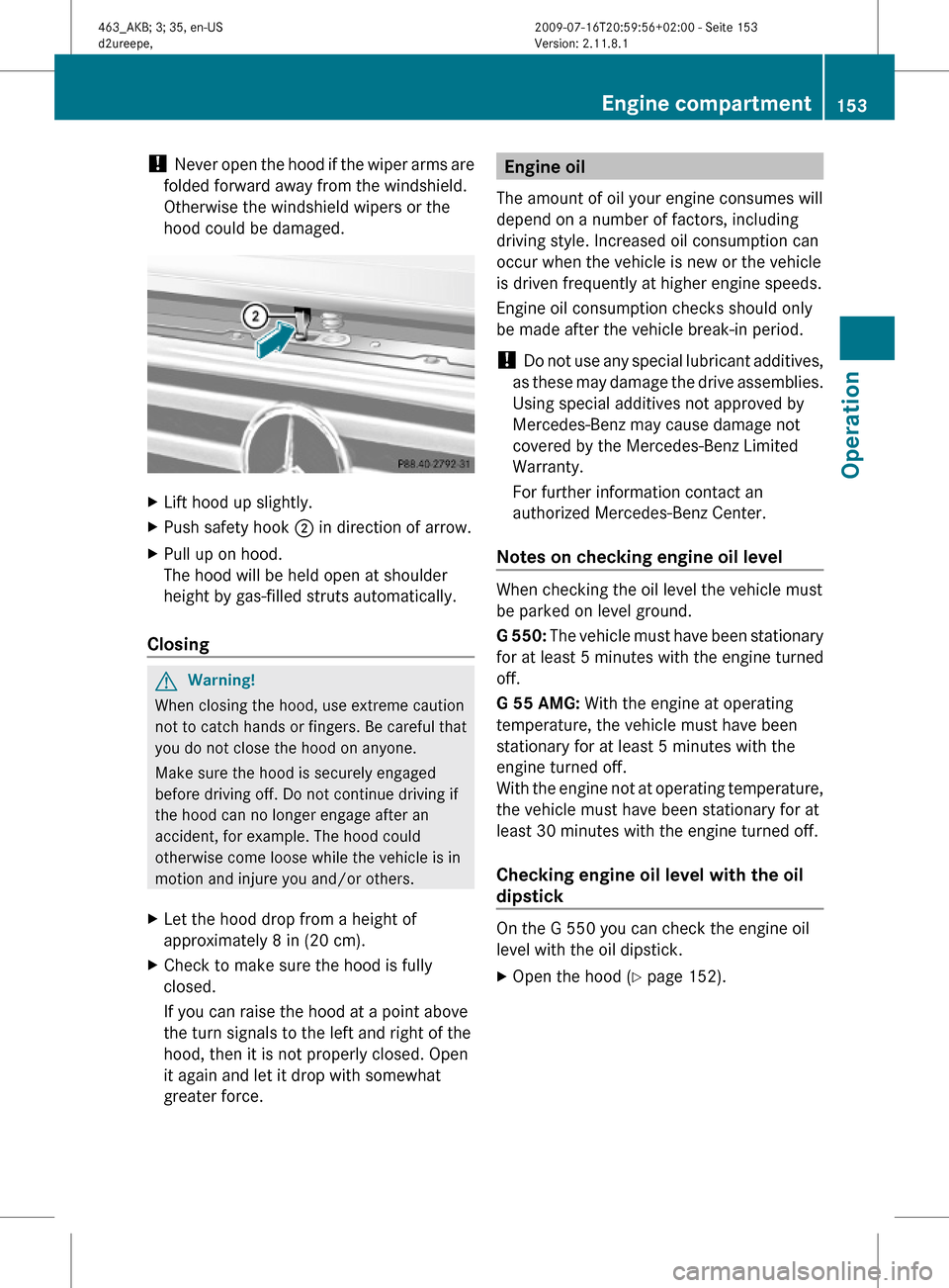
XLift hood up slightly.XPush safety hook ; in direction of arrow.XPull up on hood.
The hood will be held open at shoulder
height by gas-filled struts automatically.
Closing
GWarning!
When closing the hood, use extreme caution
not to catch hands or fingers. Be careful that
you do not close the hood on anyone.
Make sure the hood is securely engaged
before driving off. Do not continue driving if
the hood can no longer engage after an
accident, for example. The hood could
otherwise come loose while the vehicle is in
motion and injure you and/or others.
XLet the hood drop from a height of
approximately 8 in (20 cm).
XCheck to make sure the hood is fully
closed.
If you can raise the hood at a point above
the turn signals to the left and right of the
hood, then it is not properly closed. Open
it again and let it drop with somewhat
greater force.
Engine oil
The amount of oil your engine consumes will
depend on a number of factors, including
driving style. Increased oil consumption can
occur when the vehicle is new or the vehicle
is driven frequently at higher engine speeds.
Engine oil consumption checks should only
be made after the vehicle break-in period.
! Do not use any special lubricant additives,
as these may damage the drive assemblies.
Using special additives not approved by
Mercedes-Benz may cause damage not
covered by the Mercedes-Benz Limited
Warranty.
For further information contact an
authorized Mercedes-Benz Center.
Notes on checking engine oil level
When checking the oil level the vehicle must
be parked on level ground.
G 550: The vehicle must have been stationary
for at least 5 minutes with the engine turned
off.
G 55 AMG: With the engine at operating
temperature, the vehicle must have been
stationary for at least 5 minutes with the
engine turned off.
With the engine not at operating temperature,
the vehicle must have been stationary for at
least 30 minutes with the engine turned off.
Checking engine oil level with the oil
dipstick
On the G 550 you can check the engine oil
level with the oil dipstick.
XOpen the hood (Y page 152).Engine compartment153Operation463_AKB; 3; 35, en-USd2ureepe,Version: 2.11.8.12009-07-16T20:59:56+02:00 - Seite 153Z
Page 176 of 272

Letter “T” preceding the size designation:
Temporary spare tires which are high
pressure compact spares designed for
temporary emergency use only.
Tire width
Tire width : indicates the nominal tire width
in millimeters.
Aspect ratio
Aspect ratio ; is the dimensional
relationship between tire section height and
section width and is expressed in percentage.
The aspect ratio is arrived at by dividing
section height by section width.
Tire code
Tire code = indicates the tire construction
type. The “R” stands for radial tire type. Letter
“D” means diagonal or bias ply construction;
letter “B” means belted-bias ply construction.
At the tire manufacturer’s option, any tire
with a speed capability above 149 mph
(240 km/h) can include a “ZR” in the size
designation (for example: 245/40 ZR 18). For
additional information, see “Tire speed
rating” ( Y page 174).
Rim diameter
Rim diameter ? is the diameter of the bead
seat, not the diameter of the rim edge. The
rim diameter is indicated in inches (in).
Load indexGWarning!
The tire load rating must always be at least
half of the GAWR of your vehicle. Otherwise,
tire failure may be the result which may cause
an accident and/or serious injury to you or
others.
Always replace rims and tires with the same
designation, manufacturer and type as shown
on the original part.
GWarning!
Do not overload the tires by exceeding the
specified load limit as indicated on the Tire
and Loading Information placard on the
driver’s door B-pillar. Overloading the tires
can overheat them, possibly causing a
blowout. Overloading the tires can also result
in handling or steering problems, or brake
failure.
Load index A is a numerical code associated
with the maximum load a tire can support.
For example, a load rating of 91 corresponds
to a maximum load of 1356 lb (615 kg) the
tire is designed to support. See also
“Maximum tire load” (Y page 169) where the
maximum load associated with the load index
is indicated in kilograms and lbs.
For additional information on the load index,
see “Load identification” ( Y page 176).
Speed symbol GWarning!
Even when permitted by law, never operate a
vehicle at speeds greater than the maximum
speed rating of the tires.
Exceeding the maximum speed for which tires
are rated can lead to sudden tire failure,
causing loss of vehicle control and possibly
resulting in an accident and/or serious
personal injury and possible death, for you
and for others.
Regardless of the tire speed rating, local
speed limits should be obeyed. Use prudent
driving speeds appropriate to prevailing
conditions.
Speed symbol B indicates the approved
maximum speed (tire speed rating) for the
tire.
Summer tires
IndexSpeed ratingQup to 100 mph (160 km/h)Rup to 106 mph (170 km/h)Sup to 112 mph (180 km/h)Tup to 118 mph (190 km/h)174Tires and wheelsOperation
463_AKB; 3; 35, en-USd2ureepe,Version: 2.11.8.12009-07-16T20:59:56+02:00 - Seite 174
Page 179 of 272
Tire type code
Tire type code ? may, at the option of the
manufacturer, be used as a descriptive code
for identifying significant characteristics of
the tire.
Date of manufacture
The date of manufacture A identifies the
week and year of manufacture.
The first two figures identify the week,
starting with “01” to represent the first full
week of the calendar year. The second two
figures represent the year.
For example, “3208” represents the 32nd
week of 2008.
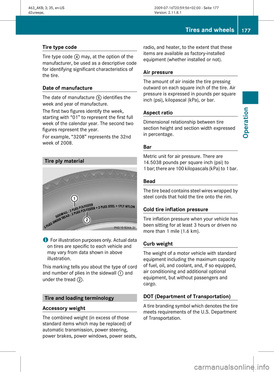
Tire ply material
iFor illustration purposes only. Actual data
on tires are specific to each vehicle and
may vary from data shown in above
illustration.
This marking tells you about the type of cord
and number of plies in the sidewall : and
under the tread ;.
Tire and loading terminology
Accessory weight
The combined weight (in excess of those
standard items which may be replaced) of
automatic transmission, power steering,
power brakes, power windows, power seats,
radio, and heater, to the extent that these
items are available as factory-installed
equipment (whether installed or not).
Air pressure
The amount of air inside the tire pressing
outward on each square inch of the tire. Air
pressure is expressed in pounds per square
inch (psi), kilopascal (kPa), or bar.
Aspect ratio
Dimensional relationship between tire
section height and section width expressed
in percentage.
Bar
Metric unit for air pressure. There are
14.5038 pounds per square inch (psi) to
1 bar; there are 100 kilopascals (kPa) to 1 bar.
Bead
The tire bead contains steel wires wrapped by
steel cords that hold the tire onto the rim.
Cold tire inflation pressure
Tire inflation pressure when your vehicle has
been sitting for at least 3 hours or driven no
more than 1 mile (1.6 km).
Curb weight
The weight of a motor vehicle with standard
equipment including the maximum capacity
of fuel, oil, and coolant, and, if so equipped,
air conditioning and additional optional
equipment, but without passengers and
cargo.
DOT (Department of Transportation)
A tire branding symbol which denotes the tire
meets requirements of the U.S. Department
of Transportation.
Tires and wheels177Operation463_AKB; 3; 35, en-USd2ureepe,Version: 2.11.8.12009-07-16T20:59:56+02:00 - Seite 177Z
Page 243 of 272
Always lower the vehicle onto sufficient
capacity jackstands before working under the
vehicle.
Always firmly engage the parking brake and
block the wheels with wheel chocks or other
sizeable objects before raising the vehicle
with the jack. Do not disengage the parking
brake while the vehicle is raised.
Make sure that the ground on which the
vehicle is standing and where you place the
jack is solid, level and not slippery. If
necessary, use a large underlay. On slippery
surfaces, such as tiled floors, you should use
a non-slip underlay, for example a rubber mat.
Do not use wooden blocks or similar objects
to support the jack. Otherwise the jack may
not be able to achieve its load-bearing
capacity if it is not at its full height.
Never start the engine when the vehicle is
raised.
Also observe the notes on the jack.
XPrevent the vehicle from rolling away by
blocking wheels with wheel chocks (not
included) or other sizeable objects.
When changing a wheel on a level surface:
XPlace a wheel chock or other sizeable
object in front of and another wheel chock
or other sizeable object behind the wheel
that is diagonally opposite to the wheel
being changed.
Always try lifting the vehicle using the jack on
a level surface. However, should
circumstances require you to do so on a hill:
XPlace wheel chocks or other sizeable
objects on the downhill side in front of both
wheels on the side opposite to the side on
which the wheel is to be changed.
GWarning!
Only jack up the vehicle on level ground or on
slight inclines/declines. Otherwise, the
vehicle could fall off the jack and injure you or
others.
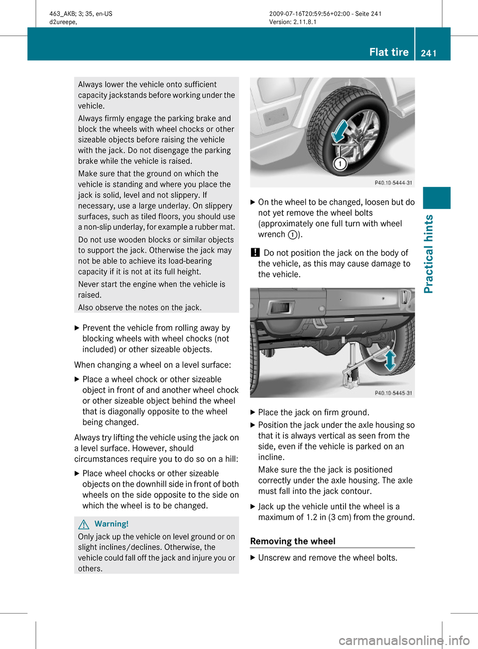
XOn the wheel to be changed, loosen but do
not yet remove the wheel bolts
(approximately one full turn with wheel
wrench :).
! Do not position the jack on the body of
the vehicle, as this may cause damage to
the vehicle.
XPlace the jack on firm ground.XPosition the jack under the axle housing so
that it is always vertical as seen from the
side, even if the vehicle is parked on an
incline.
Make sure the the jack is positioned
correctly under the axle housing. The axle
must fall into the jack contour.
XJack up the vehicle until the wheel is a
maximum of 1.2 in (3 cm) from the ground.
Removing the wheel
XUnscrew and remove the wheel bolts.Flat tire241Practical hints463_AKB; 3; 35, en-USd2ureepe,Version: 2.11.8.12009-07-16T20:59:56+02:00 - Seite 241Z
Page 258 of 272

Vehicle specification G 550 (463.237)
The quoted data apply only to the standard
vehicle. Contact an authorized Mercedes-
Benz Center for the corresponding data of all
special bodies and special equipment.Engine G 550Engine, type273Mode of operation4-stroke engine,
gasoline injectionNo. of cylinders8Bore3.86 in (98.00 mm)Stroke3.56 in (90.50 mm)Total piston
displacement333.3 cu in
(5 461 cm 3
)Compression
ratio10.7:1Output acc. to
SAE J 1349 10382 hp/6
000 rpm
(285 kW/6 000 rpm)Maximum torque
acc. to SAE J 1349391 lb-ft/
2 800 - 4 800 rpm
(530 Nm/
2 800 - 4 800 rpm)Maximum engine
speed6 500 rpmFiring order1-5-4-2-6-3-7-8Poly-V-belt2 404 mmElectrical system G 550Alternator14 V/180 AStarter motor12 V/1.4 kWElectrical system G 550Battery12 V/95 AhSpark plugs, typeNGK PLKR 7ASpark plugs,
electrode gap0.031 in (0.8 mm)Spark plugs,
tightening torque15 - 18 lb-ft
(20 - 25 Nm)Main dimensions G 550Overall vehicle
length 11186.2 in (4
730 mm)Overall vehicle
width 1279.7 in (2
025 mm)Overall vehicle
height77.8 in (1 977 mm)Wheelbase112.2 in (2 850 mm)Track, front59.7 in (1 515 mm)Track, rear59.7 in (1 515 mm)Ground
clearance, front8.5 in (217 mm)Ground
clearance, rear8.1 in (205 mm)Turning circle43.6 ft (13.3 m)10 Premium fuel required. Performance may vary with fuel octane rating.
11 Inc. spare wheel.
12 Exterior rear view mirrors folded out.256Vehicle specification G 550 (463.237)Technical data
463_AKB; 3; 35, en-USd2ureepe,Version: 2.11.8.12009-07-16T20:59:56+02:00 - Seite 256
Page 260 of 272

Main dimensions G 55 AMGOverall vehicle
height77.4 in (1 965 mm)Wheelbase112.2 in (2 850 mm)Track, front59.1 in (1 501 mm)Track, rear59.1 in (1 501 mm)Ground
clearance, front7.9 in (200 mm)Ground
clearance, rear7.9 in (200 mm)Turning circle43.6 ft (13.3 m)Weights and ratings G 55 AMGGross Vehicle
Weight Rating
(GVWR) 196
615 lb (3 000 kg)Gross Axle
Weight Rating
(GAWR), front 203
263 lb (1 480 kg)Gross Axle
Weight Rating
(GAWR), rear 203
965 lb (1 800 kg)
Rims and tires
Notes
! Only use tires which have been tested and
approved by Mercedes-Benz. Tires
approved by Mercedes-Benz are developed
to provide best possible performance in
conjunction with the driving safety systems
on your vehicle such as the ABS or the
ESP ®
. Tires specially developed for your
vehicle and tested and approved by
Mercedes-Benz can be identified by finding
the following on the tire’s sidewall:
R MO =
Mercedes-Benz Original
equipment tires
May not apply to all approved tires. For
information on tested and approved
tires, contact an authorized Mercedes-
Benz Center.
Using tires other than those approved by
Mercedes-Benz may result in damage that
is not covered by the Mercedes-Benz
Limited Warranty.
! Using tires other than those approved by
Mercedes-Benz can have detrimental
effects, such as
R poor handling characteristics
R increased noise
R increased fuel consumption
Moreover, tires and rims not approved by
Mercedes-Benz may, under load, exhibit
dimensional variations and different tire
deformation characteristics that could
cause them to come into contact with the
vehicle body or axle parts. Damage to the
tires or the vehicle may be the result.
i Further information on tires and rims is
available at any authorized Mercedes-Benz
Center. The Tire and Loading Information
placard with the recommended tire
inflation pressures for cold tires is located
on the driver’s door B-pillar. Supplemental
tire inflation pressure information for
driving at high speeds or for vehicle loads
less than the maximum loaded vehicle
condition can be found on the tire inflation
pressure label. The tire inflation pressure
label is located on the inside of the fuel filler
flap. The tire inflation pressure should be
checked regularly and should only be
adjusted on cold tires. Follow tire
19 The GVWR is the maximum permissible vehicle weight. The Gross Vehicle Weight (GVW) comprises weight
of vehicle including fuel, tools, spare wheel, installed accessories, passengers, cargo, and if applicable, trailer
tongue load. The GVW must never exceed the GVWR.
20 The GAWR is the maximum permissible axle weight.258Rims and tiresTechnical data
463_AKB; 3; 35, en-USd2ureepe,Version: 2.11.8.12009-07-16T20:59:56+02:00 - Seite 258