length MERCEDES-BENZ GL 2010 Owners Manual
[x] Cancel search | Manufacturer: MERCEDES-BENZ, Model Year: 2010, Model line: GL, Model: MERCEDES-BENZ GL 2010Pages: 380, PDF Size: 9.81 MB
Page 92 of 380
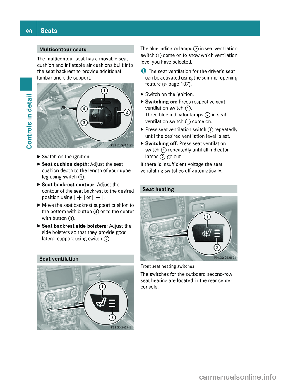
Multicontour seats
The multicontour seat has a movable seat
cushion and inflatable air cushions built into
the seat backrest to provide additional
lumbar and side support.
XSwitch on the ignition.XSeat cushion depth: Adjust the seat
cushion depth to the length of your upper
leg using switch :.
XSeat backrest contour: Adjust the
contour of the seat backrest to the desired
position using W or X.
XMove the seat backrest support cushion to
the bottom with button ? or to the center
with button =.
XSeat backrest side bolsters: Adjust the
side bolsters so that they provide good
lateral support using switch ;.
Seat ventilation
The blue indicator lamps ; in seat ventilation
switch : come on to show which ventilation
level you have selected.
iThe seat ventilation for the driver’s seat
can be activated using the summer opening
feature (Y page 107).
XSwitch on the ignition.XSwitching on: Press respective seat
ventilation switch :.
Three blue indicator lamps ; in seat
ventilation switch : come on.
XPress seat ventilation switch : repeatedly
until the desired ventilation level is set.
XSwitching off: Press seat ventilation
switch : repeatedly until all indicator
lamps ; go out.
If there is insufficient voltage the seat
ventilating switches off automatically.
Seat heating
Front seat heating switches
The switches for the outboard second-row
seat heating are located in the rear center
console.
90SeatsControls in detail
X164_AKB; 5; 31, en-USd2ureepe,Version: 2.11.8.12009-09-11T12:30:16+02:00 - Seite 90
Page 120 of 380
Rocking the vehicle
Rocking the vehicle by shifting the automatic
transmission directly between drive position
D and reverse gear R can help free a vehicle
stuck in mud or snow. The engine control
system of this vehicle electronically limits
directly shifting the automatic transmission
between drive position D and reverse gear R
to very low speeds, i.e. approximately 5 mph
(9 km/h). To shift the automatic transmission
directly between drive position D and reverse
gear R, move the gear selector lever up or
down past the resistance point.
Working on the vehicle
GWarning!
When working on the vehicle, engage the
parking brake and shift the automatic
transmission into park position P. Otherwise
the vehicle could roll away which could result
in an accident and/or serious personal injury.
Towing a trailer
XWhen you tow a trailer, shift into a lower
gear range manually if the automatic
transmission hunts between gears on
inclines.
A lower gear range and reduction of speed
reduces the potential to overload or to
overheat the engine.
For more information on trailer towing, see
“Trailer towing” (Y page 269).
Gear ranges
With the automatic transmission in drive
position D, you can limit or extend the gear
range, see “One-touch gearshifting”
(Y page 118).
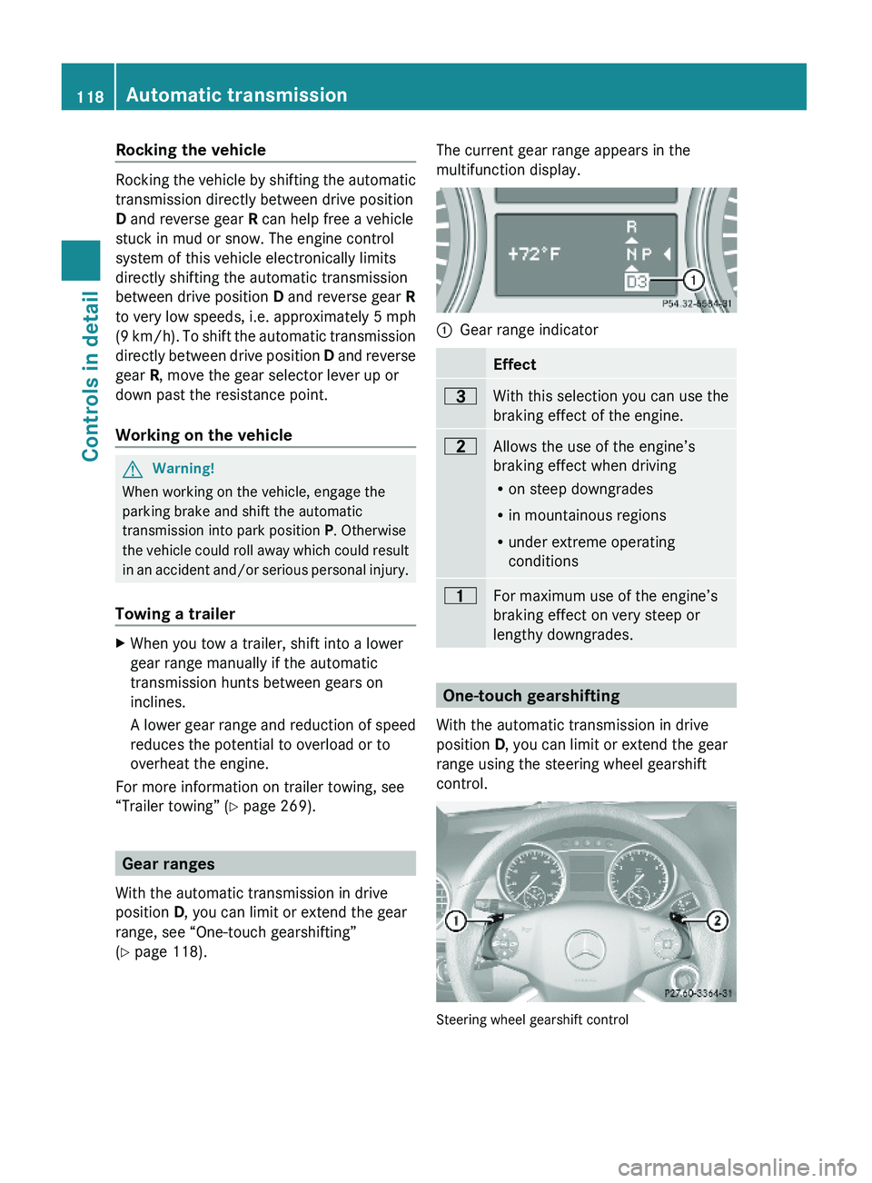
The current gear range appears in the
multifunction display.:Gear range indicator Effect=With this selection you can use the
braking effect of the engine.
5Allows the use of the engine’s
braking effect when driving
Ron steep downgrades
Rin mountainous regions
Runder extreme operating
conditions
4For maximum use of the engine’s
braking effect on very steep or
lengthy downgrades.
One-touch gearshifting
With the automatic transmission in drive
position D, you can limit or extend the gear
range using the steering wheel gearshift
control.
Steering wheel gearshift control
118Automatic transmissionControls in detail
X164_AKB; 5; 31, en-USd2ureepe,Version: 2.11.8.12009-09-11T12:30:16+02:00 - Seite 118
Page 200 of 380
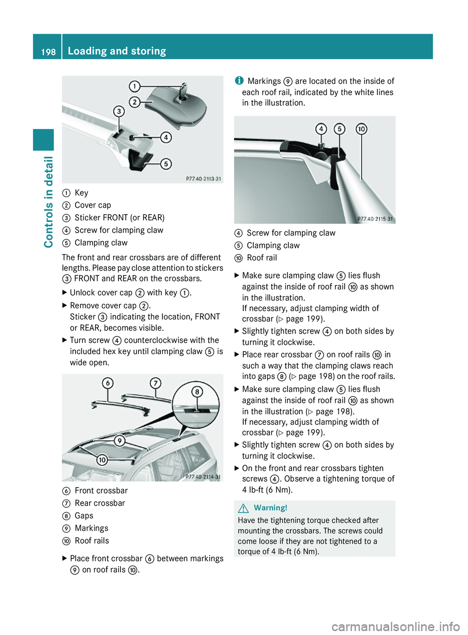
:Key;Cover cap=Sticker FRONT (or REAR)?Screw for clamping clawAClamping claw
The front and rear crossbars are of different
lengths. Please pay close attention to stickers
= FRONT and REAR on the crossbars.
XUnlock cover cap ; with key :.XRemove cover cap ;.
Sticker = indicating the location, FRONT
or REAR, becomes visible.
XTurn screw ? counterclockwise with the
included hex key until clamping claw A is
wide open.
BFront crossbarCRear crossbarDGapsEMarkingsFRoof railsXPlace front crossbar B between markings
E on roof rails F.
iMarkings E are located on the inside of
each roof rail, indicated by the white lines
in the illustration.
?Screw for clamping clawAClamping clawFRoof railXMake sure clamping claw A lies flush
against the inside of roof rail F as shown
in the illustration.
If necessary, adjust clamping width of
crossbar (Y page 199).
XSlightly tighten screw ? on both sides by
turning it clockwise.
XPlace rear crossbar C on roof rails F in
such a way that the clamping claws reach
into gaps D (Y page 198) on the roof rails.
XMake sure clamping claw A lies flush
against the inside of roof rail F as shown
in the illustration (Y page 198).
If necessary, adjust clamping width of
crossbar (Y page 199).
XSlightly tighten screw ? on both sides by
turning it clockwise.
XOn the front and rear crossbars tighten
screws ?. Observe a tightening torque of
4 lb-ft (6 Nm).
GWarning!
Have the tightening torque checked after
mounting the crossbars. The screws could
come loose if they are not tightened to a
torque of 4 lb-ft (6 Nm).
198Loading and storingControls in detail
X164_AKB; 5; 31, en-USd2ureepe,Version: 2.11.8.12009-09-11T12:30:16+02:00 - Seite 198
Page 224 of 380
Reprogramming a single signal
transmitter button
To program a device using a signal
transmitter button previously trained, follow
these steps:
XSwitch on the ignition.XPress and hold the desired signal
transmitter button ( ;, = or ?). Do not
release the button.
Indicator lamp : will begin to flash after
20 seconds.XWithout releasing the signal transmitter
button, proceed with programming starting
with step 3.
Operation of integrated remote control
XSwitch on the ignition.XSelect and press the appropriate
integrated signal transmitter button ( ;,
= or ?) to activate the remote controlled
device.
The integrated remote control transmitter
continues to send the signal as long as the
button is pressed – up to 20 seconds.
Erasing the integrated remote control
memory
i If you sell your vehicle, erase the codes of
all three channels.
XSwitch on the ignition.XSimultaneously press and hold outer signal
transmitter buttons ; and ?, for
approximately 20 seconds, until indicator
lamp : flashes rapidly. Do not hold for
longer than 30 seconds.
The codes of all three channels are erased.Programming tips
If you are having difficulty programming the
integrated remote control, here are some
helpful tips:
R Check the frequency of hand-held remote
control A (typically located on the reverse
side of the remote). The integrated remote
control is compatible with radio-frequency
devices operating between 280-390 MHz.
R Put a new battery in hand-held remote
control A. This will increase the likelihood
of the hand-held remote control sending a
stronger and more accurate signal to the
integrated remote control.
R While performing step 3, hold hand-held
remote control A at different lengths and
angles from the signal transmitter button
( ; , = or ?) you are programming.
Attempt varying angles at the distance of 2
to 12 inches (5 to 30 cm) away or the same
angle at varying distances.
R If another hand-held remote control is
available for the same device, try the
programming steps again using that other
hand-held remote control. Make sure new
batteries are in the hand-held remote
control before beginning the procedure.
R Straighten the antenna wire from the
garage door opener assembly. This may
help improve transmitting and/or receiving
signals.
i Certain types of garage door openers are
incompatible with the integrated remote
control. If you should experience further
difficulties with programming the
integrated remote control, contact an
authorized Mercedes-Benz Center, or call
the Mercedes-Benz Customer Assistance
Center (USA only) at
1-800-FOR-MERCedes (1-800-367-6372),
or the HomeLink ®
Hotline (USA only) at
1-800-355-3515, or the Customer Service
(Canada only) at 1-800-387-0100.
222Useful featuresControls in detail
X164_AKB; 5; 31, en-USd2ureepe,Version: 2.11.8.12009-09-11T12:30:16+02:00 - Seite 222
Page 261 of 380
maneuvers. Do not use the cruise control
system under such conditions.
When the vehicle is in danger of skidding, shift
the automatic transmission to neutral
position N. Try to keep the vehicle under
control by corrective steering action.
i For information on driving with snow
chains, see “Snow chains” ( Y page 258).
Road salts and chemicals can adversely
affect braking efficiency. Increased pedal
force may become necessary to produce the
normal brake effect.
Depressing the brake pedal periodically when
traveling at length on salt-strewn roads can
bring road-salt-impaired braking efficiency
back to normal.
If the vehicle is parked after being driven on
salt-treated roads, the braking efficiency
should be tested as soon as possible after
driving is resumed.GWarning!
Make sure not to endanger any other road
users when carrying out these braking
maneuvers.
Driving instructions
Drive sensibly – save fuel
To save fuel you should:
R Keep tires at the recommended inflation
pressures.
R Remove unnecessary loads.
R Remove carriers when not in use.
R Remove the crossbars when not in use.
R Allow engine to warm up under low load
use.
R Avoid frequent acceleration and
deceleration.
R Have all maintenance work performed at
the intervals specified in the Maintenance
Booklet and as required by the
Maintenance system. Contact an
authorized Mercedes-Benz Center.
Fuel consumption is also increased by driving
in cold weather, in stop-and-go traffic, on
short trips and in mountainous areas.
Drinking and driving
GWarning!
Drinking and driving and/or taking drugs and
driving are very dangerous combinations.
Even a small amount of alcohol or drugs can
affect your reflexes, perceptions and
judgment.
The possibility of a serious or even fatal
accident are greatly increased when you drink
or take drugs and drive.
Do not drink or take drugs and drive or allow
anyone to drive who has been drinking or
taking drugs.
Pedals
GWarning!
Make sure absolutely no objects are
obstructing the pedals’ range of movement.
Keep the driver’s footwell clear of all
obstacles. If there are any floormats or
carpets in the footwell, make sure that the
pedals still have sufficient clearance.
During sudden driving or braking maneuvers,
the objects could get caught between the
pedals. You could then no longer brake or
accelerate. This could lead to accidents and
injury.
Power assistance
GWarning!
There is no power assistance for the steering
and the brake when the engine is not running.
Driving instructions259OperationX164_AKB; 5; 31, en-USd2ureepe,Version: 2.11.8.12009-09-11T12:30:16+02:00 - Seite 259Z
Page 267 of 380
100% grade which is equivalent to a slope
angle of 45°. Keep in mind that the
climbing ability of the vehicle depends on
terrain conditions.
R Shift automatic transmission into gear
range 1 (Y page 118).
R Drive slowly.
R Avoid excessive engine speeds – drive with
moderate engine speeds (max. 3 000 rpm).
R Utilize the engine’s braking power when
descending a slope, observe the engine
speed (do not overrev the engine). Apply
the service brake as needed.
i For maximum engine speed, see
“Tachometer” (Y page 125) and see vehicle
specification for your vehicle
( Y page 362).
R Check the brakes after a lengthy
downgrade drive.GWarning!
Never turn the vehicle around on steep
inclines. The vehicle might roll over. If the
vehicle cannot complete the attempted climb,
back it down in reverse gear.
i The hill-start assist system supports you
when driving uphill.
For more information, see “Hill-start assist
system” ( Y page 155).
Traction in steep terrain
The maximum vehicle climbing ability is a
100% grade which is equivalent to a slope
angle of 45°. Keep in mind that the climbing
ability of the vehicle depends on terrain
conditions.
Be easy on the accelerator and watch for
continuous wheel traction when driving in
steep terrain.
i The 4-ETS helps greatly when starting out
on a steep incline when the front wheels
have then the tendency to slip due to the
weight shifting towards the rear axle.
The 4-ETS recognizes the situation and
limits the torque for the front wheels by
braking them.
Simultaneously the torque for the rear
wheels is increased.
i Vehicles with enhanced off-road package
are equipped with automatic locks for the
center and rear axle differential to improve
vehicle traction.
Driving across a hilltop
Decelerate just ahead of a hilltop (do not shift
automatic transmission into neutral position
N ), to prevent the vehicle from speeding up
too much after climbing a hill.
Use the momentum of the vehicle to drive
across the hilltop.
After climbing a hill, driving in this manner
prevents the vehicle from:
R losing ground contact when cresting hills
R losing its forward momentum
R speeding up too much after climbing the hill
Driving downhill
R Drive slowly.
R Do not drive at an angle to the incline. Steer
into the line of gravity and drive with the
front wheels pointing straight downhill.
Otherwise, the vehicle may slide sideways
off the path and roll over.
R Shift automatic transmission into gear
range 1 (Y page 118).
R On steep inclines, use the Downhill Speed
Regulation ( Y page 155).
R Utilize the engine’s braking power to
reduce vehicle speed.
If this is insufficient, apply the brakes
gently. Make sure the vehicle is moving in
the line of gravity.
R Check the brakes after a lengthy
downgrade drive.
Driving instructions265OperationX164_AKB; 5; 31, en-USd2ureepe,Version: 2.11.8.12009-09-11T12:30:16+02:00 - Seite 265Z
Page 272 of 380
The values as measured must not exceed
the weight limits listed under “Vehicle and
trailer weights and ratings” ( Y page 269).
Coupling a trailer GWarning!
While you are coupling or decoupling a trailer,
make sure nobody locks or unlocks the
vehicle and/or opens or closes doors or the
tailgate.
The vehicle’s level could change and you
could endanger yourself and/or others as a
result.
Make sure that you do not operate the ADS
button or the vehicle level control system
when coupling/decoupling the trailer.
Observe maximum permitted trailer
dimensions (width and length).
Most states and all Canadian provinces
require
R safety chains between the towing vehicle
and the trailer
The chains should be criss-crossed under
the trailer tongue. They must be attached
to the hitch receiver, and not to the
vehicle’s bumper or axle.
Make sure to leave enough slack in the
chains to permit turning corners.
R a separate brake system at various trailer
weights
R a break-away switch on trailers with a
separate brake system.
Check with your local state laws for specific
requirements.
The switch activates the trailer brakes in
the possible event that the trailer might
separate from the tow vehicle.
! Do not connect a trailer brake system (if
trailer is so equipped) directly to the
vehicle’s hydraulic brake system, as your
vehicle is equipped with antilock brakes. If
you do, neither the vehicle’s brakes nor the
trailer’s brakes will function properly.
i The provided vehicle electrical wiring
harness for trailer towing has a brake signal
wire for hook-up to a brake controller.XMake sure the automatic transmission is in
park position P (Y page 115).XEngage the parking brake for the vehicle
( Y page 112).XStart the engine ( Y page 108).XSelect the highway level ( Y page 159).XVehicles with Adaptive Damping System
(ADS):
Set the ADS to AUTO or COMF
( Y page 159).XTurn off the engine ( Y page 113).XClose all doors and the tailgate.XAttach the trailer.XPlug in all electrical connectors.
i
When you are towing a trailer, the vehicle
level always remains in the highway setting.
The following applies additionally when
towing a trailer:
R The vehicle is lowered to the highway
level when it reaches a speed of 5 mph
(8 km/h) if not set to highway level.
R The highspeed level is not available.
The restrictions that apply to towing also
apply when using accessories that are
connected to the trailer power socket, such
as a bicycle rack.
Towing a trailer
There are many different laws, including
speed limit restrictions, having to do with
trailer towing. Make sure your rig will be legal,
not only for where you reside, but also for
where you will be driving. A good source for
this information can be the police or local
authorities.
Note the following, when driving with a trailer:
R In order to gain skill and an understanding
of the vehicle’s behavior, you should
270Driving instructionsOperation
X164_AKB; 5; 31, en-USd2ureepe,Version: 2.11.8.12009-09-11T12:30:16+02:00 - Seite 270
Page 346 of 380
Do not tighten the wheel bolts when the
vehicle is raised. Otherwise the vehicle could
fall off the jack.
Wheel bolt : must be used for 19", 20", and
21" light alloy wheels. Wheel bolt ; must be
used for the Minispare wheel. The wheel bolts
for the Minispare wheel are located in vehicle
tool kit.
! Wheel bolts ; must be used when
mounting the Minispare wheel. The use of
any wheel bolts other than wheel bolts ;
for the Minispare wheel will damage the
vehicle’s brakes.
GWarning!
Make sure to use the original length wheel
bolts when remounting the original wheel
after it has been repaired.
XClean contact surfaces of wheel and wheel
hub.
! To avoid paint damage, place wheel flat
against hub and hold it there while
installing first wheel bolt.
XGuide the spare wheel onto the alignment
bolt and push it on.
XInsert the wheel bolts and tighten them
slightly.
XUnscrew the alignment bolt.XInstall the last wheel bolt and tighten it
slightly.
Lowering the vehicle
XAttach ratchet to vehicle jack so that the
word DOWN can be seen.
Lower the vehicle until the vehicle is resting
fully on its own weight:
XTurn ratchet in direction DOWN.XRemove the jack.XTighten the five wheel bolts evenly,
following the diagonal sequence illustrated
(: to A), until all bolts are tight. Observe
a tightening torque of 110 lb-ft (150 Nm).
344Flat tirePractical hints
X164_AKB; 5; 31, en-USd2ureepe,Version: 2.11.8.12009-09-11T12:30:16+02:00 - Seite 344
Page 353 of 380
Never lean over batteries while connecting or
jump starting. You might get injured.
Battery fluid contains sulfuric acid. Do not
allow this fluid to come in contact with eyes,
skin or clothing. In case it does, immediately
flush affected area with water, and seek
medical help if necessary.
A battery will also produce hydrogen gas,
which is flammable and explosive. Keep
flames or sparks away from battery, avoid
improper connection of jumper cables,
smoking, etc.
Attempting to jump start a frozen battery can
result in it exploding, causing personal injury.
Read all instructions before proceeding.
! Do not tow-start the vehicle. You could
otherwise seriously damage the automatic
transmission which is not covered by the
Mercedes-Benz Limited Warranty.
! Jump starting should only be performed
using the jump-start terminals located in
the engine compartment.
Avoid repeated and lengthy starting
attempts.
Do not attempt to start the engine using a
battery quick-charge unit.
If the engine does not run after several
unsuccessful starting attempts, have it
checked at the nearest authorized
Mercedes-Benz Center.
Excessive unburned fuel generated by
repeated failed starting attempts may
damage the catalytic converter 20
and may
present a fire risk.
Make sure the jumper cables do not have
loose or missing insulation.
Make sure the cable clamps do not touch
any other metal part while the other end is
still attached to a battery.If the battery is discharged, the engine can be
started with jumper cables and the fully
charged battery of another vehicle or an
equivalent starter pack. Observe the
following:
R Access to the battery is not possible on all
vehicles. If you cannot access the battery
of the other vehicle, provide jump start
power by an external battery or starter
pack.
R Jump starting should only be performed
when the engine and catalytic converter 21
are cold.
R Do not start the engine if the battery is
frozen. Let the battery thaw out first.
R Only jump start from batteries with the
same voltage rating (12 V). Jump starting
with a more powerful battery could damage
the vehicle’s electrical system. Such
damage will not be covered by the
Mercedes-Benz Limited Warranty.
R Only use jumper cables with sufficient
cross-section and insulated terminal
clamps.
R Always make sure the jumper cables are
not on or near pulleys, fans or other parts
that move when an engine is started or
running.
R Should the battery be drained completely,
let the donating power source charge the
vehicle for several minutes before
reattempting the starting process.
The jump-start contacts are located in the
engine compartment on the passenger side.XMake sure the two vehicles do not touch.XSwitch off all electrical consumers.XEngage the parking brake.XMake sure the automatic transmission is in
park position P.XOpen the hood ( Y page 228).20
Vehicles with gasoline engine only.
21 Vehicles with gasoline engine only.Jump starting351Practical hintsX164_AKB; 5; 31, en-USd2ureepe,Version: 2.11.8.12009-09-11T12:30:16+02:00 - Seite 351Z
Page 364 of 380
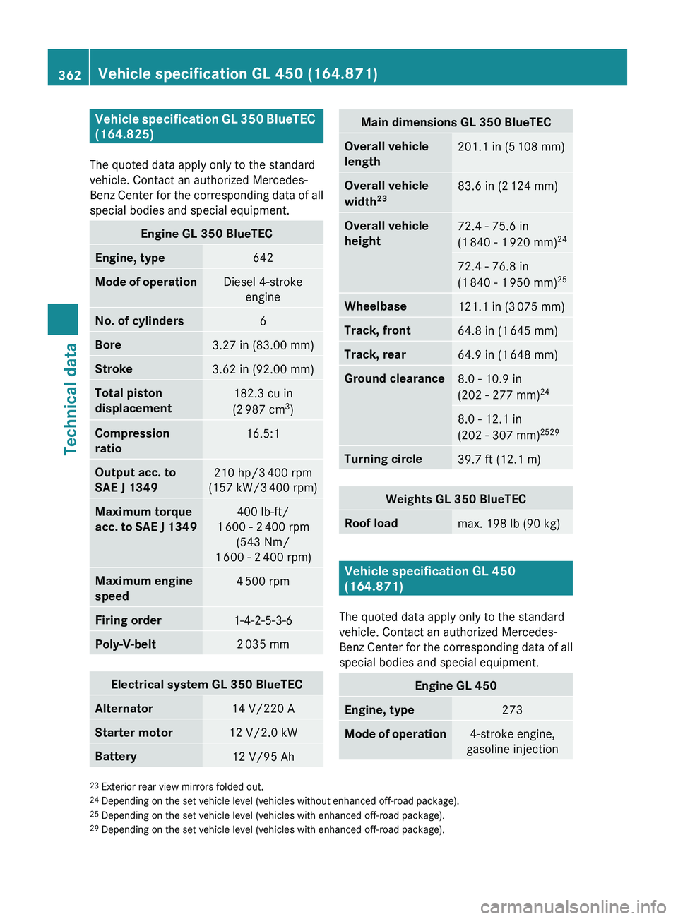
Vehicle specification GL 350 BlueTEC
(164.825)
The quoted data apply only to the standard
vehicle. Contact an authorized Mercedes-
Benz Center for the corresponding data of all
special bodies and special equipment.Engine GL 350 BlueTECEngine, type642Mode of operationDiesel 4-stroke engineNo. of cylinders6Bore3.27 in (83.00 mm)Stroke3.62 in (92.00 mm)Total piston
displacement182.3 cu in
(2 987 cm 3
)Compression
ratio16.5:1Output acc. to
SAE J 1349210 hp/3 400 rpm
(157 kW/3 400 rpm)Maximum torque
acc. to SAE J 1349400 lb-ft/
1 600 - 2 400 rpm
(543 Nm/
1 600 - 2 400 rpm)Maximum engine
speed4 500 rpmFiring order1-4-2-5-3-6Poly-V-belt2 035 mmElectrical system GL 350 BlueTECAlternator14 V/220 AStarter motor12 V/2.0 kWBattery12 V/95 AhMain dimensions GL 350 BlueTECOverall vehicle
length201.1 in (5 108 mm)Overall vehicle
width 2383.6 in (2
124 mm)Overall vehicle
height72.4 - 75.6 in
(1 840 - 1 920 mm) 2472.4 - 76.8 in
(1 840 - 1 950 mm) 25Wheelbase121.1 in (3
075 mm)Track, front64.8 in (1 645 mm)Track, rear64.9 in (1 648 mm)Ground clearance8.0 - 10.9 in
(202 - 277 mm) 248.0 - 12.1 in
(202 - 307 mm) 2529Turning circle39.7 ft (12.1 m)Weights GL 350 BlueTECRoof loadmax. 198 lb (90 kg)
Vehicle specification GL 450
(164.871)
The quoted data apply only to the standard
vehicle. Contact an authorized Mercedes-
Benz Center for the corresponding data of all
special bodies and special equipment.
Engine GL 450Engine, type273Mode of operation4-stroke engine,
gasoline injection23 Exterior rear view mirrors folded out.
24 Depending on the set vehicle level (vehicles without enhanced off-road package).
25 Depending on the set vehicle level (vehicles with enhanced off-road package).
29 Depending on the set vehicle level (vehicles with enhanced off-road package).362Vehicle specification GL 450 (164.871)Technical data
X164_AKB; 5; 31, en-USd2ureepe,Version: 2.11.8.12009-09-11T12:30:16+02:00 - Seite 362