set clock MERCEDES-BENZ GL 2010 Owners Manual
[x] Cancel search | Manufacturer: MERCEDES-BENZ, Model Year: 2010, Model line: GL, Model: MERCEDES-BENZ GL 2010Pages: 380, PDF Size: 9.81 MB
Page 8 of 380
Central locking
Automatic ................................ 74, 138
KEYLESS-GO .................................... 71
Locking/unlocking from inside ........75
SmartKey ......................................... 70
Central locking/unlocking switch ..... 75
Certification label .............................. 360
Children in the vehicle
Air bags ........................................... 37
BabySmart™ air bag deactivation
system ............................................. 46
Child safety locks (rear doors) .........60
Child seat anchors – LATCH-type ....59
Indicator lamp, front passenger
front air bag off (Canada only) .........46
Indicator lamp, front passenger
front air bag off (USA only) ..............42
Infant and child restraint systems .... 56
OCS (Occupant Classification
System) ........................................... 42
Override switch ................................ 60
Safety notes ..................................... 55
Tether anchorage points ..................58
Top tether ........................................ 58
Child safety
see Children in the vehicle
Child seat anchors – LATCH-type
see Children in the vehicle
Chrome-plated exhaust tip,
cleaning .............................................. 281
Cigarette lighter ................................ 212
Climate control system .................... 172
3-zone automatic climate control ..181
Air conditioning .....................177, 186
Air conditioning refrigerant ............371
Air distribution ....................... 178, 188
Air recirculation mode ...........180, 190
Air volume ............................. 179, 189
Automatic mode ....................178, 187
Climate control .............................. 175
Deactivating system ..............177, 185
Front defroster ...................... 179, 189
Residual heat and
ventilation .............................. 180, 191
Temperature .......................... 178, 187
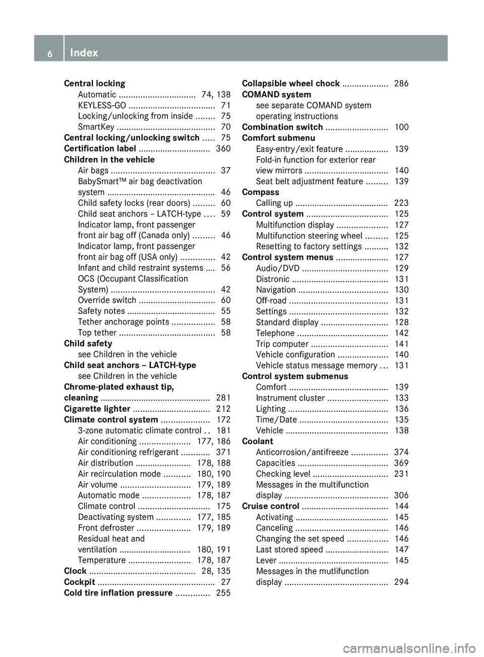
Clock ............................................ 28, 135
Cockpit ................................................. 27
Cold tire inflation pressure .............. 255Collapsible wheel chock ................... 286
COMAND system see separate COMAND system
operating instructions
Combination switch .......................... 100
Comfort submenu
Easy-entry/exit feature .................. 139
Fold-in function for exterior rear
view mirrors ................................... 140
Seat belt adjustment feature .........139
Compass
Calling up ....................................... 223
Control system .................................. 125
Multifunction display .....................127
Multifunction steering wheel .........125
Resetting to factory settings ..........132
Control system menus ...................... 127
Audio/DVD .................................... 129
Distronic ........................................ 131
Navigation ..................................... 130
Off-road ......................................... 131
Settings ......................................... 132
Standard display ............................ 128
Telephone ...................................... 142
Trip computer ................................ 141
Vehicle configuration .....................140
Vehicle status message memory ...131
Control system submenus
Comfort ......................................... 139
Instrument cluster .........................133
Lighting .......................................... 136
Time/Date ..................................... 135
Vehicle ........................................... 138
Coolant
Anticorrosion/antifreeze ...............374
Capacities ...................................... 369
Checking level ............................... 231
Messages in the multifunction
display ........................................... 306
Cruise control .................................... 144
Activating ....................................... 145
Canceling ....................................... 146
Changing the set speed .................146
Last stored speed ..........................147
Lever .............................................. 145
Messages in the mutlifunction
display ........................................... 2946IndexX164_AKB; 5; 31, en-USd2ureepe,Version: 2.11.8.12009-09-11T12:30:16+02:00 - Seite 6
Page 9 of 380
Resume function ............................ 147
Setting current speed ....................145
Cup holders ........................................ 209
Curb weight ....................................... 255
Customer Assistance Center (CAC) ... 23
Customer Relations Department ....... 23
D
Dashboard see Instrument cluster
Data recording ..................................... 24
Date, Setting ...................................... 135
Daytime running lamp mode .............. 99
Switching on or off ......................... 136
Deep water
see Standing water
Defroster
Rear window .................................. 191
Windshield ............................. 179, 189
Delayed shut-off
Exterior lamps ................................ 137
Interior lighting .............................. 138
Department of Transportation
see DOT
Diesel engine
Preglow indicator lamp ....................29
Diesel fuel
see Fuel
Differential locks ............................... 121
A few words about .........................122
Messages in the multifunction
display ................................... 123, 302
Switching ....................................... 122
Difficulties
While driving .................................. 111
With starting .................................. 110
Digital clock
see Clock
Digital speedometer ......................... 129
Dimensions (vehicle) see Vehicle specification
Direction of rotation (tires) .............. 246
Displays
Digital speedometer ......................129
Distronic ........................................ 149
Maintenance service indicator .......273
Messages in the multifunction
display ........................................... 287
Multifunction display .....................127
Outside temperature .............129, 135
Symbol messages ..........................299
Text messages ............................... 288
Trip computer ................................ 141
Vehicle status message memory ...131
Vehicle system settings .................132
Distronic ............................................ 147
Cleaning system sensor cover .......278
Control system .............................. 131
Distance warning function .............155
Distance warning
lamp ...................................... 149, 319
Driving with .................................... 153
Menu ............................................. 150
Messages in the multifunction
display ........................................... 294
Resume function ............................ 152
Sensor cover .................................. 278
Speed settings ............................... 151
Door control panel .............................. 34
Door handles ........................................ 34
Doors
Child safety locks ............................ 60
Locking/unlocking (KEYLESS-GO) ...71
Locking/unlocking (SmartKey) ........70
Messages in the multifunction
display ........................................... 304
Opening from inside ......................... 74
Remote door unlock (Tele Aid) .......219
Unlocking (Mechanical key) ...........323
DOT (Department of
Transportation) .................................. 255
Downhill Speed Regulation see DSR
Drinking and driving ......................... 259
Driving
Abroad ........................................... 272
Hydroplaning ................................. 262
Instructions ........................... 108, 259
In winter ........................................ 258
Off-road ......................................... 262
Problems ....................................... 111
Safety systems ................................ 61
Systems ......................................... 144Index7X164_AKB; 5; 31, en-USd2ureepe,Version: 2.11.8.12009-09-11T12:30:16+02:00 - Seite 7
Page 30 of 380
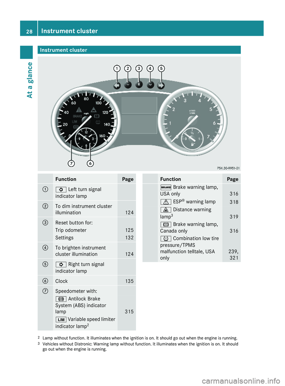
Instrument clusterFunctionPage:# Left turn signal
indicator lamp
;To dim instrument cluster
illumination124
=Reset button for: Trip odometer125Settings132?To brighten instrument
cluster illumination124
A! Right turn signal
indicator lamp
BClock 135CSpeedometer with: ! Antilock Brake
System (ABS) indicator
lamp 315
È Variable speed limiter
indicator lamp2FunctionPage$ Brake warning lamp,
USA only 316
d ESP® warning lamp 318· Distance warning
lamp3319
J Brake warning lamp,
Canada only316
h Combination low tire
pressure/TPMS
malfunction telltale, USA
only
239,
321
2Lamp without function. It illuminates when the ignition is on. It should go out when the engine is running.3Vehicles without Distronic: Warning lamp without function. It illuminates when the ignition is on. It shouldgo out when the engine is running.
28Instrument clusterAt a glance
X164_AKB; 5; 31, en-USd2ureepe,Version: 2.11.8.12009-09-11T12:30:16+02:00 - Seite 28
Page 137 of 380
Selecting display (digital speedometer or
outside temperature) for status indicator
XPress button V or U repeatedly until
the Settings menu appears in the
multifunction display.
XPress button &.XMove the selection marker with button
W or X to the Instrument
Cluster submenu.
XPress button & or * repeatedly until
the message Status Line Display
appears in the multifunction display.
The selection marker is on the current
setting.
XPress button W or X to select the
desired setting.
The selected display is then shown
continuously in the status indicator (lower
display).
The other display now appears in the
Standard display menu (Y page 128).
Time/Date submenu
Access the Time/Date submenu via the
Settings menu. Use the Time/Date
submenu to change the time and date display
settings.
The following functions are available:
RSetting the time (Y page 135)
RSetting the date (Y page 135)
If your vehicle is equipped with the COMAND
system and navigation module, see separate
COMAND system operating instructions for
information on how to set the time and date.
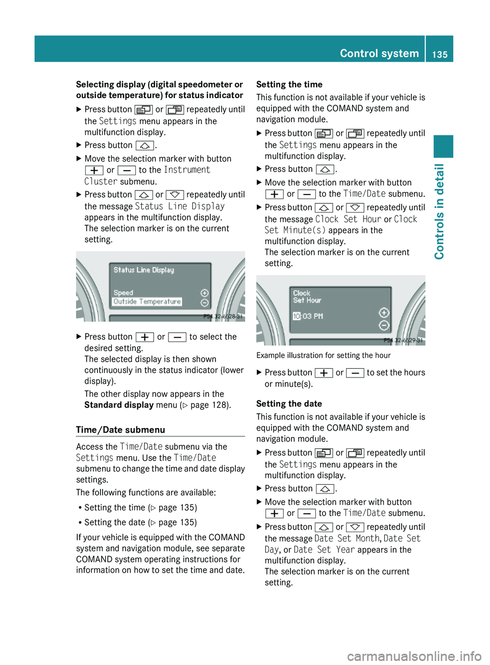
Setting the time
This function is not available if your vehicle is
equipped with the COMAND system and
navigation module.
XPress button V or U repeatedly until
the Settings menu appears in the
multifunction display.
XPress button &.XMove the selection marker with button
W or X to the Time/Date submenu.
XPress button & or * repeatedly until
the message Clock Set Hour or Clock
Set Minute(s) appears in the
multifunction display.
The selection marker is on the current
setting.
Example illustration for setting the hour
XPress button W or X to set the hours
or minute(s).
Setting the date
This function is not available if your vehicle is
equipped with the COMAND system and
navigation module.
XPress button V or U repeatedly until
the Settings menu appears in the
multifunction display.
XPress button &.XMove the selection marker with button
W or X to the Time/Date submenu.
XPress button & or * repeatedly until
the message Date Set Month, Date Set
Day, or Date Set Year appears in the
multifunction display.
The selection marker is on the current
setting.
Control system135Controls in detailX164_AKB; 5; 31, en-USd2ureepe,Version: 2.11.8.12009-09-11T12:30:16+02:00 - Seite 135Z
Page 180 of 380
The air conditioning uses the refrigerant
R134a. This refrigerant is free of CFCs which
are harmful to the ozone layer.
! If the air conditioning cannot be activated
again, this indicates that the air
conditioning is losing refrigerant. The
compressor has turned off.
Have the air conditioning checked at the
nearest authorized Mercedes-Benz Center.
Automatic mode
When operating the climate control system in
automatic mode, the interior air temperature,
air volume and air distribution are adjusted
automatically.
In automatic mode, cooling with
dehumidification is switched on. This function
can be switched off if necessary.
GWarning!
If you switch off the air conditioning, the
vehicle will not be cooled when weather
conditions are warm. The windows can fog up
more quickly. Window fogging may impair
visibility and endanger you and others.
XSet the desired temperature
( Y page 178).XActivating: Press button Ã.
The indicator lamp in the button comes on.
The air volume and air distribution are
adjusted automatically.
i The settings for the passenger side are
also used for the rear passenger
compartment.
XDeactivating: Press button I or K .
The indicator lamp in button à goes out.
The automatic operation of air volume
switches off. The selected blower speed isshown in air volume display G
( Y page 175).
or
XPress air distribution button ¯, P , or
O .
The indicator lamp in button à goes out.
The automatic operation of air distribution
switches off.
Setting the temperature
You can adjust the air temperature on each
side of the passenger compartment. You
should raise or lower the temperature setting
in small increments, preferably starting at
72‡ (22†).
XIncreasing/decreasing: Turn
temperature control : and/or C
( Y page 175) slightly clockwise or
counterclockwise.
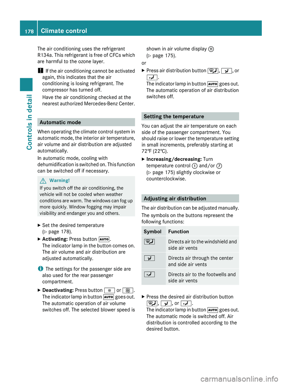
Adjusting air distribution
The air distribution can be adjusted manually.
The symbols on the buttons represent the
following functions:
SymbolFunction¯Directs air to the windshield and
side air ventsPDirects air through the center
and side air ventsODirects air to the footwells and
side air ventsXPress the desired air distribution button
¯ , P , or O .
The indicator lamp in button à goes out.
The automatic mode is switched off. Air
distribution is controlled according to the
desired button.178Climate controlControls in detail
X164_AKB; 5; 31, en-USd2ureepe,Version: 2.11.8.12009-09-11T12:30:16+02:00 - Seite 178
Page 201 of 380
XAttach cover caps (Y page 198) and lock
them.
XStore key and hex key back into the storage
well (Y page 284).
Adjusting the clamping widths of the
crossbars
GWarning!
Only install the crossbars at the exact
locations designated on the roof rails. The
designated locations for the front crossbars
are between the markings engraved on the
inside of the roof rails. The designated
locations for the rear crossbars are between
the gaps on the roof rails.
Otherwise, the crossbars, mounted
accessories and the objects attached to them
could come loose from the vehicle causing an
accident, thereby injuring you and other
persons and/or causing damage to property,
including damage to your vehicle.
The clamping widths of the crossbars are
factory set for your vehicle. These clamping
widths are solely intended for the designated
positions.
Only install the crossbars at the designated
locations and pay attention to the stickers
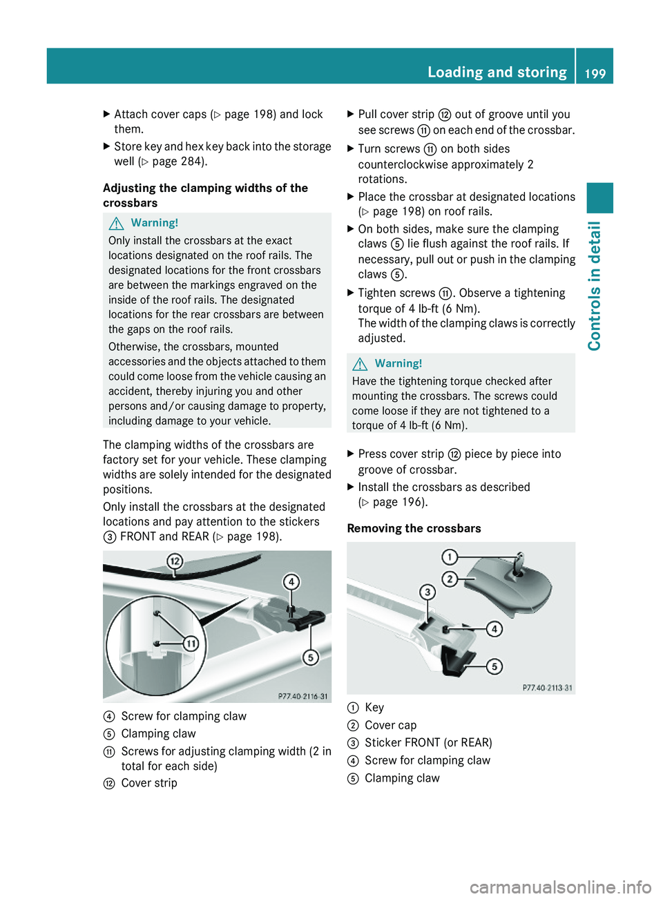
= FRONT and REAR (Y page 198).
?Screw for clamping clawAClamping clawGScrews for adjusting clamping width (2 in
total for each side)
HCover stripXPull cover strip H out of groove until you
see screws G on each end of the crossbar.
XTurn screws G on both sides
counterclockwise approximately 2
rotations.
XPlace the crossbar at designated locations
(Y page 198) on roof rails.
XOn both sides, make sure the clamping
claws A lie flush against the roof rails. If
necessary, pull out or push in the clamping
claws A.
XTighten screws G. Observe a tightening
torque of 4 lb-ft (6 Nm).
The width of the clamping claws is correctly
adjusted.
GWarning!
Have the tightening torque checked after
mounting the crossbars. The screws could
come loose if they are not tightened to a
torque of 4 lb-ft (6 Nm).
XPress cover strip H piece by piece into
groove of crossbar.
XInstall the crossbars as described
(Y page 196).
Removing the crossbars
:Key;Cover cap=Sticker FRONT (or REAR)?Screw for clamping clawAClamping clawLoading and storing199Controls in detailX164_AKB; 5; 31, en-USd2ureepe,Version: 2.11.8.12009-09-11T12:30:16+02:00 - Seite 199Z
Page 230 of 380

iLeaving the engine running and the fuel
filler cap open can cause the yellow fuel
tank reserve warning lamp to flash and the
malfunction indicator lamp ! (USA
only) or ; (Canada only) to illuminate.
For more information, see also “Practical
hints” ( Y page 320).XRemove the SmartKey from the starter
switch.
KEYLESS-GO: Open the driver’s door. This
puts the starter switch in position 0, same
as with the SmartKey removed from the
starter switch. The driver’s door then can
be closed again.XOpening: Press fuel filler flap : at the
point indicated by the arrow.XTurn fuel filler cap ; counterclockwise.XTake off fuel filler cap ;.
!
The fuel filler cap is tethered to the fuel
filler neck. Do not drop the cap. It could
damage the vehicle paint finish.
XSet fuel filler cap ; on fuel filler flap :.XFully insert filler nozzle unit and refuel.XOnly fill your tank until the filler nozzle unit
cuts out – do not top off or overfill .XClosing: Turn fuel filler cap ; clockwise
until it audibly engages.
i Close the fuel filler flap before locking the
vehicle. Otherwise the flap locking pin will
prevent closing the fuel filler flap.
XClose fuel filler flap :.
Low outside temperatures (diesel
engine)
! Do not fill the tank with gasoline. Do not
blend diesel fuel with gasoline or kerosene.
The fuel system and engine will otherwise
be damaged, which is not covered by the
Mercedes-Benz Limited Warranty.
To prevent malfunctions, diesel fuel with
improved cold flow characteristics is offered
in the winter months. Check with your fuel
retailer.
Check regularly and before a long trip
For information on quantities and
requirements of operating agents, see “Fuels,
coolants, lubricants, etc.” ( Y page 368).
Check the following:
R Engine oil level ( Y page 230)
R Tire inflation pressure ( Y page 237)
R Coolant level ( Y page 231)
R Vehicle lighting ( Y page 328)
R Washer system and headlamp cleaning
system ( Y page 232)
R Brake fluid ( Y page 233)
Engine compartment
Hood
GWarning!
Do not pull the release lever while the vehicle
is in motion. Otherwise the hood could be
forced open by passing air flow.
This could cause the hood to come loose and
injure you and/or others.
Opening
GWarning!
Do not open the hood when the engine is
overheated. You could be seriously injured.
Observe the coolant temperature display to
determine whether the engine may be
overheated. If you see flames or smoke
coming from the engine compartment, move
away from the vehicle. Wait until the engine
has cooled. If necessary, call the fire
department.
228Engine compartmentOperation
X164_AKB; 5; 31, en-USd2ureepe,Version: 2.11.8.12009-09-11T12:30:16+02:00 - Seite 228
Page 289 of 380
XRemoving: Open the tailgate (Y page 75).XLift the cargo compartment floor and
secure it on the upper cargo compartment
lip (Y page 284).
! To prevent damage, always disengage the
securing hook from upper cargo
compartment lip and lower the cargo
compartment floor before closing the
tailgate.
XRemove the jack from the vehicle tool kit
(Y page 285).
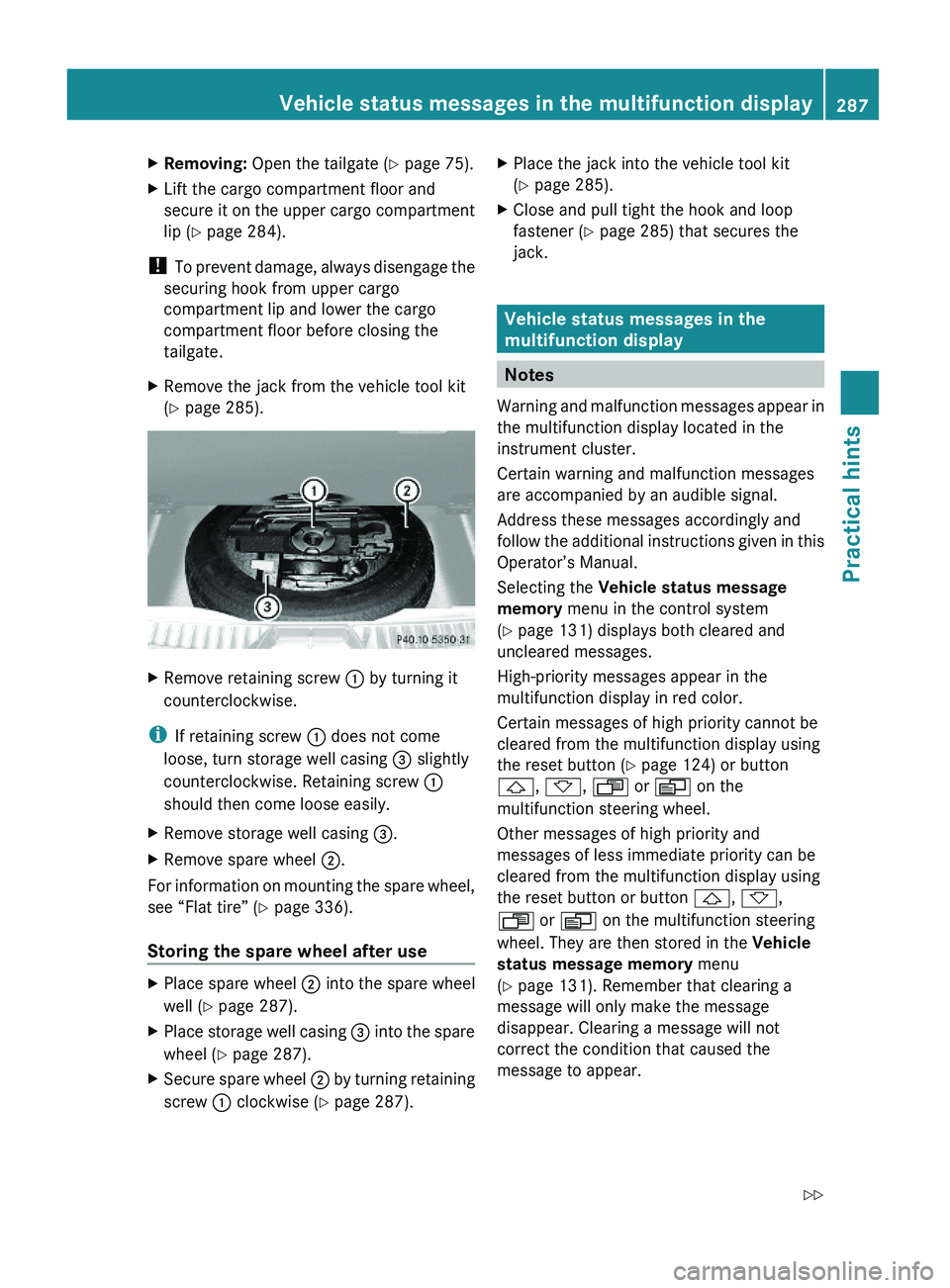
XRemove retaining screw : by turning it
counterclockwise.
iIf retaining screw : does not come
loose, turn storage well casing = slightly
counterclockwise. Retaining screw :
should then come loose easily.
XRemove storage well casing =.XRemove spare wheel ;.
For information on mounting the spare wheel,
see “Flat tire” (Y page 336).
Storing the spare wheel after use
XPlace spare wheel ; into the spare wheel
well (Y page 287).
XPlace storage well casing = into the spare
wheel (Y page 287).
XSecure spare wheel ; by turning retaining
screw : clockwise (Y page 287).
XPlace the jack into the vehicle tool kit
(Y page 285).
XClose and pull tight the hook and loop
fastener (Y page 285) that secures the
jack.
Vehicle status messages in the
multifunction display
Notes
Warning and malfunction messages appear in
the multifunction display located in the
instrument cluster.
Certain warning and malfunction messages
are accompanied by an audible signal.
Address these messages accordingly and
follow the additional instructions given in this
Operator’s Manual.
Selecting the Vehicle status message
memory menu in the control system
(Y page 131) displays both cleared and
uncleared messages.
High-priority messages appear in the
multifunction display in red color.
Certain messages of high priority cannot be
cleared from the multifunction display using
the reset button (Y page 124) or button
&, *, U or V on the
multifunction steering wheel.
Other messages of high priority and
messages of less immediate priority can be
cleared from the multifunction display using
the reset button or button &, *,
U or V on the multifunction steering
wheel. They are then stored in the Vehicle
status message memory menu
(Y page 131). Remember that clearing a
message will only make the message
disappear. Clearing a message will not
correct the condition that caused the
message to appear.
Vehicle status messages in the multifunction display287Practical hintsX164_AKB; 5; 31, en-USd2ureepe,Version: 2.11.8.12009-09-11T12:30:16+02:00 - Seite 287Z
Page 352 of 380
The factory-equipped battery may only be
replaced with a battery that
R has the same security features
R is of identical size
R is of identical voltage
R is of identical capacity
! As any other battery, the battery may
discharge if you do not operate the vehicle
for an extended period of time. Have the
battery disconnected at a qualified
workshop or an authorized Mercedes-Benz
Center in such a case. You may also
connect an accessory battery charge unit
expressly approved by Mercedes-Benz for
your vehicle model to maintain the battery
charge. Contact an authorized Mercedes-
Benz Center for further information.
The battery, the battery ventilation hose
and the lateral plug must always be
securely installed when the vehicle is in
operation.
! Never loosen or detach battery terminal
clamps while the engine is running or the
SmartKey is in the starter switch or
KEYLESS-GO button is in position 1.
Otherwise the alternator and other
electronic components could be severely
damaged.
Have the battery checked regularly at an
authorized Mercedes-Benz Center.
Refer to Maintenance Booklet for
maintenance intervals or contact an
authorized Mercedes-Benz Center for
further information.
i After battery power was interrupted, do
the following:
R Set the clock ( Y page 135).
Vehicles with COMAND system with
navigation module: Time and date are set
automatically.
R Synchronize the door windows
( Y page 107).R
Synchronize the power tilt/sliding
sunroof ( Y page 194).
R Synchronize the exterior rear view
mirrors ( Y page 96).
Charging the battery
GWarning!
Never charge a battery while still installed in
the vehicle unless the accessory battery
charge unit approved by Mercedes-Benz is
being used. Gases may escape during
charging and could cause an explosion that
may result in personal injury, paint damage or
corrosion.
An accessory battery charge unit specially
adapted for Mercedes-Benz vehicles and
tested and approved by Mercedes-Benz is
available. It permits the charging of the
battery in its installed position. Contact an
authorized Mercedes-Benz Center for
information and availability.
Charge battery in accordance with the
separate instructions for the accessory
battery charger.
Have the battery charged at an authorized
Mercedes-Benz Center. If you charge the
battery yourself, follow the operating
instructions for your charging device.
Only use a battery charge unit with a
maximum charging voltage of 14.8 V.
XCharge battery in accordance with the
instructions of the battery charger
manufacturer.
Jump starting
GWarning!
Failure to follow these directions will cause
damage to the electronic components, and
can lead to a battery explosion and severe
injury or death.
350Jump startingPractical hints
X164_AKB; 5; 31, en-USd2ureepe,Version: 2.11.8.12009-09-11T12:30:16+02:00 - Seite 350