MERCEDES-BENZ GL 2011 Owners Manual
Manufacturer: MERCEDES-BENZ, Model Year: 2011, Model line: GL, Model: MERCEDES-BENZ GL 2011Pages: 376, PDF Size: 17.39 MB
Page 271 of 376
There are two securing hooks : on each side
of the cargo compartment.
Luggage compartment cover
Important safety notes
! When loading the vehicle, make sure that
you do not stack the load in the cargo
compartment higher than the lower edge of
the side windows. Do not place heavy
objects on top of the cargo compartment
cover.
The cargo compartment cover can be
attached behind the 2nd or 3rd row of seats.
Extending/retracting the luggage
compartment cover
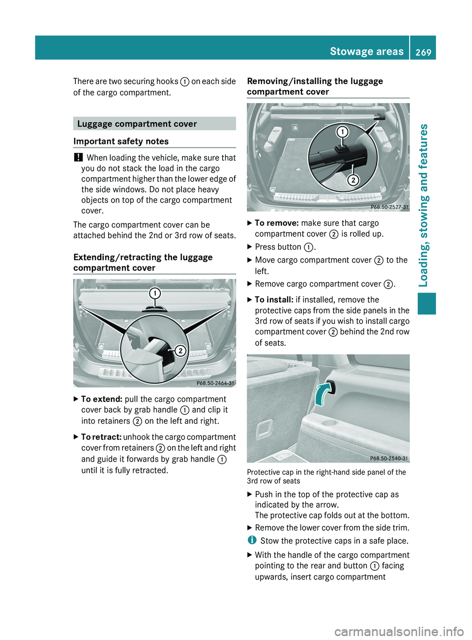
XTo extend: pull the cargo compartment
cover back by grab handle : and clip it
into retainers ; on the left and right.XTo retract: unhook the cargo compartment
cover from retainers ; on the left and right
and guide it forwards by grab handle :
until it is fully retracted.Removing/installing the luggage
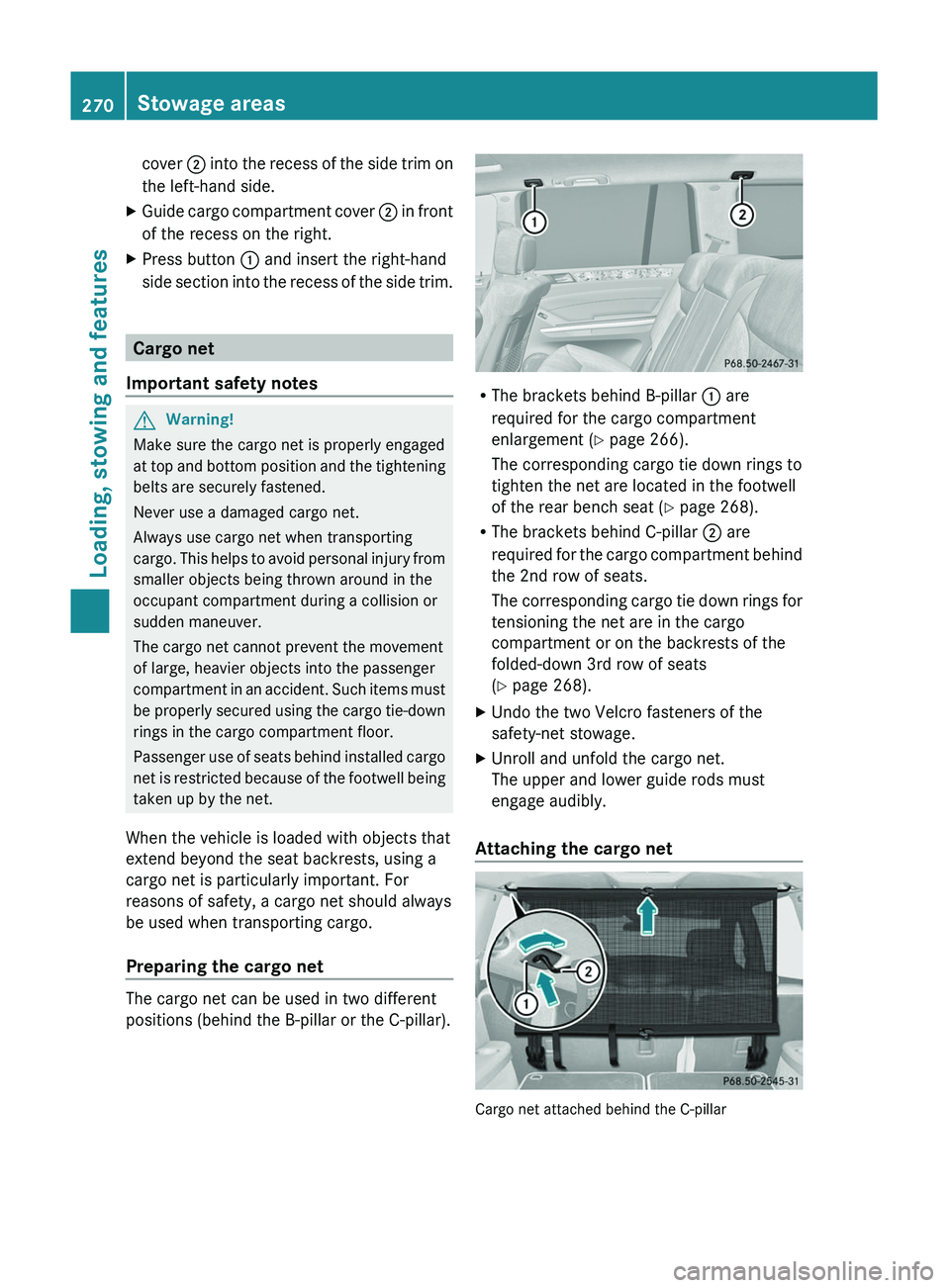
compartment coverXTo remove: make sure that cargo
compartment cover ; is rolled up.XPress button :.XMove cargo compartment cover ; to the
left.XRemove cargo compartment cover ;.XTo install: if installed, remove the
protective caps from the side panels in the
3rd row of seats if you wish to install cargo
compartment cover ; behind the 2nd row
of seats.
Protective cap in the right-hand side panel of the
3rd row of seats
XPush in the top of the protective cap as
indicated by the arrow.
The protective cap folds out at the bottom.XRemove the lower cover from the side trim.
i Stow the protective caps in a safe place.
XWith the handle of the cargo compartment
pointing to the rear and button : facing
upwards, insert cargo compartmentStowage areas269Loading, stowing and featuresBA 164.8 USA, CA Edition B 2011; 1; 2, en-USd2sboikeVersion: 3.0.3.52010-04-21T15:08:44+02:00 - Seite 269Z
Page 272 of 376
cover ; into the recess of the side trim on
the left-hand side.XGuide cargo compartment cover ; in front
of the recess on the right.XPress button : and insert the right-hand
side section into the recess of the side trim.
Cargo net
Important safety notes
GWarning!
Make sure the cargo net is properly engaged
at top and bottom position and the tightening
belts are securely fastened.
Never use a damaged cargo net.
Always use cargo net when transporting
cargo. This helps to avoid personal injury from
smaller objects being thrown around in the
occupant compartment during a collision or
sudden maneuver.
The cargo net cannot prevent the movement
of large, heavier objects into the passenger
compartment in an accident. Such items must
be properly secured using the cargo tie-down
rings in the cargo compartment floor.
Passenger use of seats behind installed cargo
net is restricted because of the footwell being
taken up by the net.
When the vehicle is loaded with objects that
extend beyond the seat backrests, using a
cargo net is particularly important. For
reasons of safety, a cargo net should always
be used when transporting cargo.
Preparing the cargo net
The cargo net can be used in two different
positions (behind the B-pillar or the C-pillar).
R The brackets behind B-pillar : are
required for the cargo compartment
enlargement ( Y page 266).
The corresponding cargo tie down rings to
tighten the net are located in the footwell
of the rear bench seat ( Y page 268).
R The brackets behind C-pillar ; are
required for the cargo compartment behind
the 2nd row of seats.
The corresponding cargo tie down rings for
tensioning the net are in the cargo
compartment or on the backrests of the
folded-down 3rd row of seats
( Y page 268).
XUndo the two Velcro fasteners of the
safety-net stowage.XUnroll and unfold the cargo net.
The upper and lower guide rods must
engage audibly.
Attaching the cargo net
Cargo net attached behind the C-pillar
270Stowage areasLoading, stowing and features
BA 164.8 USA, CA Edition B 2011; 1; 2, en-USd2sboikeVersion: 3.0.3.52010-04-21T15:08:44+02:00 - Seite 270
Page 273 of 376
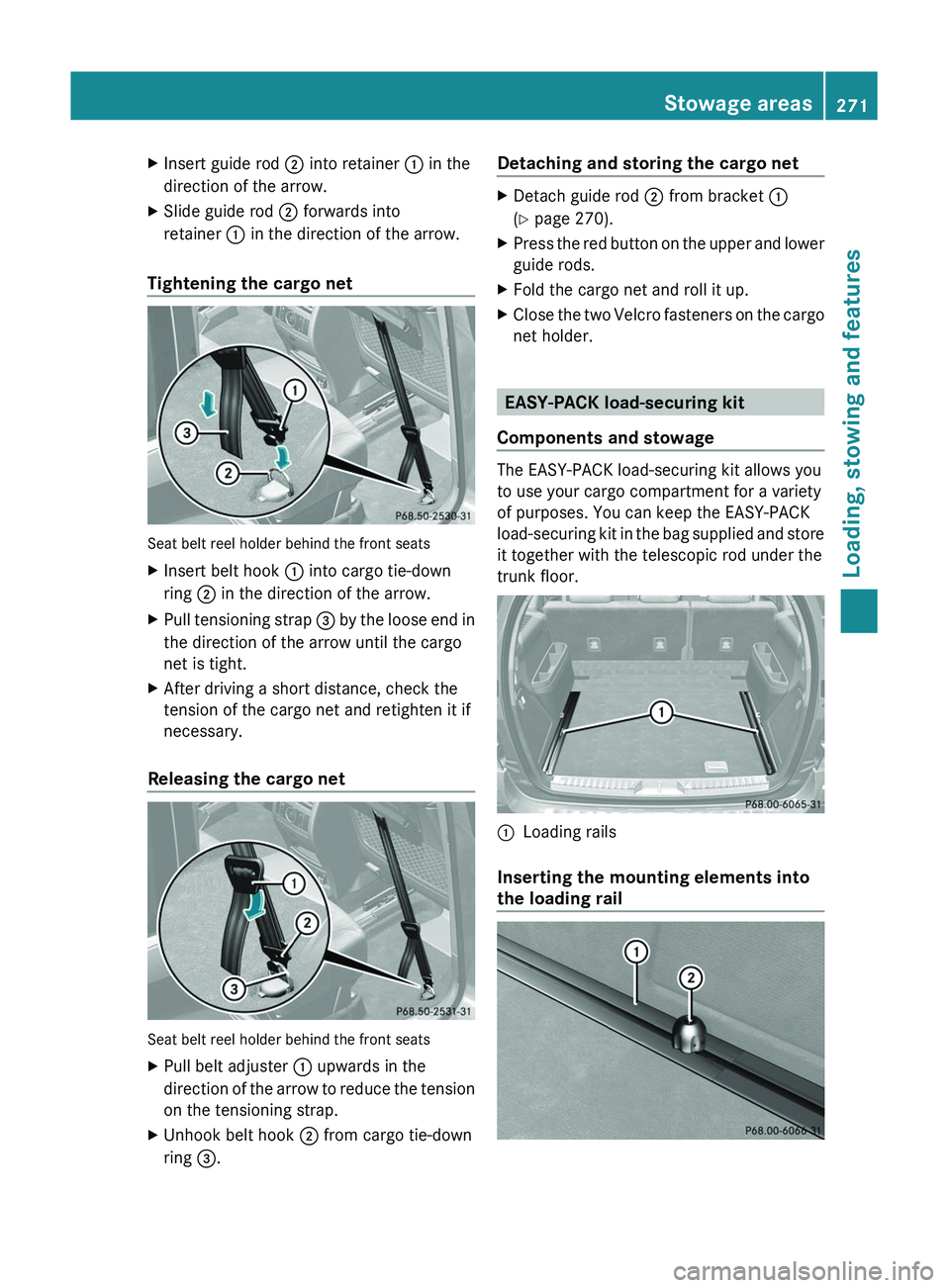
XInsert guide rod ; into retainer : in the
direction of the arrow.XSlide guide rod ; forwards into
retainer : in the direction of the arrow.
Tightening the cargo net
Seat belt reel holder behind the front seats
XInsert belt hook : into cargo tie-down
ring ; in the direction of the arrow.XPull tensioning strap = by the loose end in
the direction of the arrow until the cargo
net is tight.XAfter driving a short distance, check the
tension of the cargo net and retighten it if
necessary.
Releasing the cargo net
Seat belt reel holder behind the front seats
XPull belt adjuster : upwards in the
direction of the arrow to reduce the tension
on the tensioning strap.XUnhook belt hook ; from cargo tie-down
ring =.Detaching and storing the cargo netXDetach guide rod ; from bracket :
( Y page 270).XPress the red button on the upper and lower
guide rods.XFold the cargo net and roll it up.XClose the two Velcro fasteners on the cargo
net holder.
EASY-PACK load-securing kit
Components and stowage
The EASY-PACK load-securing kit allows you
to use your cargo compartment for a variety
of purposes. You can keep the EASY-PACK
load-securing kit in the bag supplied and store
it together with the telescopic rod under the
trunk floor.
:Loading rails
Inserting the mounting elements into
the loading rail
Stowage areas271Loading, stowing and featuresBA 164.8 USA, CA Edition B 2011; 1; 2, en-USd2sboikeVersion: 3.0.3.52010-04-21T15:08:44+02:00 - Seite 271Z
Page 274 of 376
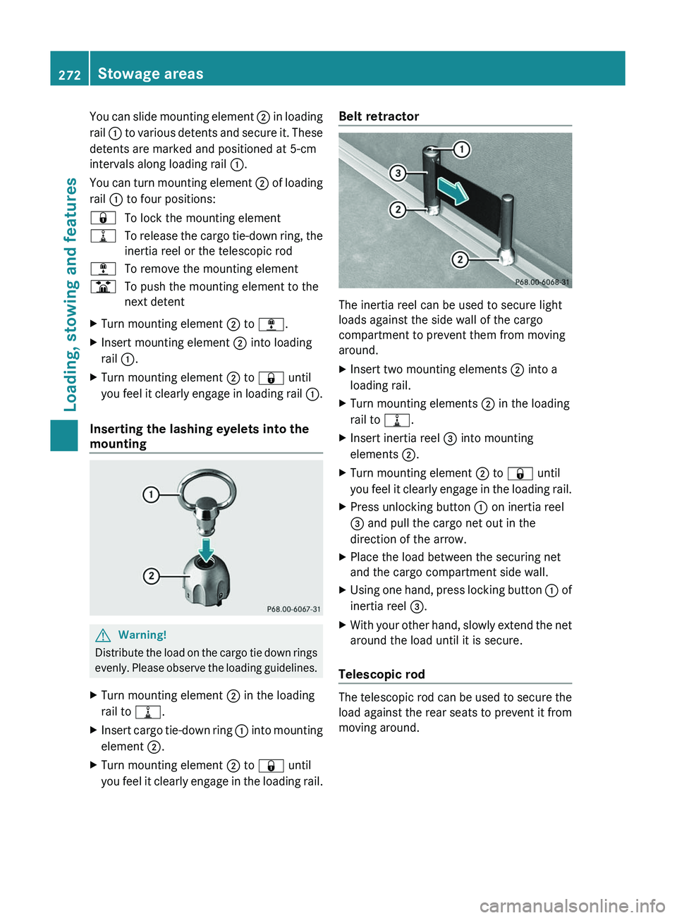
You can slide mounting element ; in loading
rail : to various detents and secure it. These
detents are marked and positioned at 5-cm
intervals along loading rail :.
You can turn mounting element ; of loading
rail : to four positions:&To lock the mounting element=To release the cargo tie-down ring, the
inertia reel or the telescopic rod;To remove the mounting elementBTo push the mounting element to the
next detentXTurn mounting element ; to ; .XInsert mounting element ; into loading
rail :.XTurn mounting element ; to & until
you feel it clearly engage in loading rail :.
Inserting the lashing eyelets into the
mounting
GWarning!
Distribute the load on the cargo tie down rings
evenly. Please observe the loading guidelines.
XTurn mounting element ; in the loading
rail to =.XInsert cargo tie-down ring : into mounting
element ;.XTurn mounting element ; to & until
you feel it clearly engage in the loading rail.Belt retractor
The inertia reel can be used to secure light
loads against the side wall of the cargo
compartment to prevent them from moving
around.
XInsert two mounting elements ; into a
loading rail.XTurn mounting elements ; in the loading
rail to =.XInsert inertia reel = into mounting
elements ;.XTurn mounting element ; to & until
you feel it clearly engage in the loading rail.XPress unlocking button : on inertia reel
= and pull the cargo net out in the
direction of the arrow.XPlace the load between the securing net
and the cargo compartment side wall.XUsing one hand, press locking button : of
inertia reel =.XWith your other hand, slowly extend the net
around the load until it is secure.
Telescopic rod
The telescopic rod can be used to secure the
load against the rear seats to prevent it from
moving around.
272Stowage areasLoading, stowing and features
BA 164.8 USA, CA Edition B 2011; 1; 2, en-USd2sboikeVersion: 3.0.3.52010-04-21T15:08:44+02:00 - Seite 272
Page 275 of 376
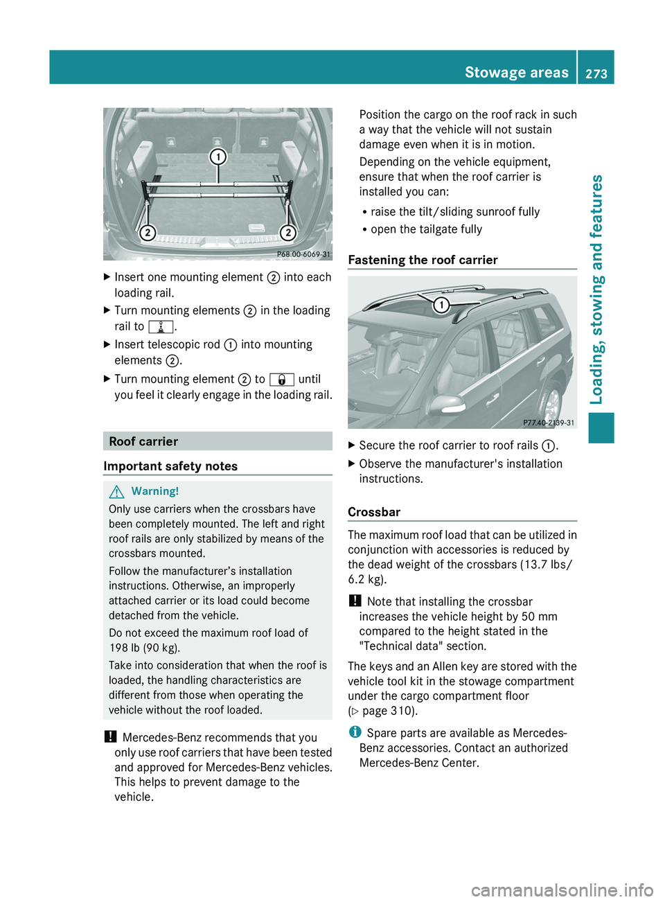
XInsert one mounting element ; into each
loading rail.XTurn mounting elements ; in the loading
rail to =.XInsert telescopic rod : into mounting
elements ;.XTurn mounting element ; to & until
you feel it clearly engage in the loading rail.
Roof carrier
Important safety notes
GWarning!
Only use carriers when the crossbars have
been completely mounted. The left and right
roof rails are only stabilized by means of the
crossbars mounted.
Follow the manufacturer’s installation
instructions. Otherwise, an improperly
attached carrier or its load could become
detached from the vehicle.
Do not exceed the maximum roof load of
198 lb (90 kg).
Take into consideration that when the roof is
loaded, the handling characteristics are
different from those when operating the
vehicle without the roof loaded.
! Mercedes-Benz recommends that you
only use roof carriers that have been tested
and approved for Mercedes-Benz vehicles.
This helps to prevent damage to the
vehicle.
Position the cargo on the roof rack in such
a way that the vehicle will not sustain
damage even when it is in motion.
Depending on the vehicle equipment,
ensure that when the roof carrier is
installed you can:
R raise the tilt/sliding sunroof fully
R open the tailgate fully
Fastening the roof carrierXSecure the roof carrier to roof rails :.XObserve the manufacturer's installation
instructions.
Crossbar
The maximum roof load that can be utilized in
conjunction with accessories is reduced by
the dead weight of the crossbars (13.7 lbs/
6.2 kg).
! Note that installing the crossbar
increases the vehicle height by 50 mm
compared to the height stated in the
"Technical data" section.
The keys and an Allen key are stored with the
vehicle tool kit in the stowage compartment
under the cargo compartment floor
( Y page 310).
i Spare parts are available as Mercedes-
Benz accessories. Contact an authorized
Mercedes-Benz Center.
Stowage areas273Loading, stowing and featuresBA 164.8 USA, CA Edition B 2011; 1; 2, en-USd2sboikeVersion: 3.0.3.52010-04-21T15:08:44+02:00 - Seite 273Z
Page 276 of 376
Installing the crossbarsGWarning!
Please follow these installation instructions
carefully. Caution should be exercised to
avoid damage to the vehicle while installing
the crossbars. Also, be careful not to injure
yourself or others while installing and
adjusting the crossbars or loading items on
them.
Each individual step of the installation
instructions, the warning notices, the general
safety precautions and the instructions for
use must be followed exactly. If the crossbars
are not mounted correctly, they and the
objects attached to them could come loose
from your vehicle and cause an accident,
thereby injuring you and other persons and/
or causing damage to property, including
damage to your vehicle.
GWarning!
Every time the crossbars are mounted, before
you set off on a journey and periodically
during longer journeys, check all the screws
on the crossbars to make sure that they are
secure, and tighten them if necessary. Repeat
these checks at regular intervals as road-
surface conditions dictate, and at least after
every 1500 miles (2500 km) of continuous
use.
Otherwise, the crossbars, mounted
accessories and the objects attached to them
could come loose from the vehicle causing an
accident, thereby injuring you and other
persons and/or causing damage to property,
including damage to your vehicle.
Do not use lubricant on the screws of the
crossbars. The screws could work loose and
the crossbars could become detached from
your vehicle, together with the objects
attached to them causing an accident,
thereby injuring you and other persons and/
or causing damage to property, including
damage to your vehicle.
GWarning!
Only install the crossbars at the exact
locations designated on the roof rails. The
designated locations for the front crossbars
are between the markings engraved on the
inside of the roof rails. The designated
locations for the rear crossbars are between
the gaps on the roof rails.
Otherwise, the crossbars, mounted
accessories and the objects attached to them
could come loose from the vehicle causing an
accident, thereby injuring you and other
persons and/or causing damage to property,
including damage to your vehicle.
GWarning!
A roof load creates a greater surface area
exposed to the wind and causes the vehicle
to have a higher center of gravity, thereby
changing the vehicle’s driving characteristics.
Accordingly, the additional weight on the roof
of the vehicle can have a detrimental effect
on braking, cornering and acceleration.
Never exceed the maximum permissible roof
load or the maximum permissible vehicle
weight, even when accessories for the
crossbars (e.g. ski racks, bicycle racks, etc.)
are being used. Overloading the vehicle could
result in an accident. When calculating the
weight placed on the roof please make sure
to add the weight of the crossbars, accessory
racks and the load carried together.
Always adapt your driving style to the road,
traffic and weather conditions, and drive with
added caution when the roof is loaded.
Always drive with extreme care when the
carrier is loaded. Take into consideration that
when the carrier is loaded, the handling
characteristics are different from those when
operating the vehicle without a carrier loaded.
GWarning!
Do not use accessories which have not been
approved by Mercedes-Benz for use in
conjunction with these crossbars. If non-
approved accessories are used, these
274Stowage areasLoading, stowing and features
BA 164.8 USA, CA Edition B 2011; 1; 2, en-USd2sboikeVersion: 3.0.3.52010-04-21T15:08:44+02:00 - Seite 274
Page 277 of 376
accessories and/or the objects attached to
them could come loose from the vehicle,
thereby injuring you and other persons and/
or causing damage to property, including
damage to your vehicle.
! Have a second person assist you when
installing the crossbars. Otherwise, the
vehicle could be damaged.
! Objects that are attached to crossbar
system accessories must not limit or
obstruct the movement of the sliding
sunroof. Otherwise, the tilt/sliding sunroof
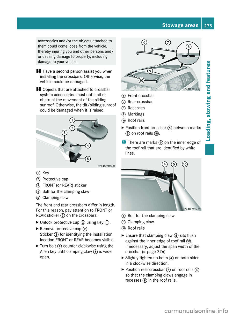
could be damaged when it is raised.:Key;Protective cap=FRONT (or REAR) sticker?Bolt for the clamping clawAClamping claw
The front and rear crossbars differ in length.
For this reason, pay attention to FRONT or
REAR sticker = on the crossbars.
XUnlock protective cap ; using key :.XRemove protective cap ;.
Sticker = for identifying the installation
location FRONT or REAR becomes visible.XTurn bolt ? counter-clockwise using the
Allen key until clamping claw A is wide
open.BFront crossbarCRear crossbarDRecessesEMarkingsFRoof railsXPosition front crossbar B between marks
E on roof rails F.
i
There are marks E on the inner edge of
the roof rail that are identified by white
lines.
?Bolt for the clamping clawAClamping clawFRoof railsXEnsure that clamping claw A sits flush
against the inner edge of roof rail F.
If necessary, adjust the span width of the
crossbar ( Y page 276).XSlightly tighten up bolts ? on both sides
in a clockwise direction.XPosition rear crossbar C on roof rails F
so that the clamping claws engage in
recesses D in the roof rails.Stowage areas275Loading, stowing and featuresBA 164.8 USA, CA Edition B 2011; 1; 2, en-USd2sboikeVersion: 3.0.3.52010-04-21T15:08:44+02:00 - Seite 275Z
Page 278 of 376
XEnsure that clamping claw A sits flush
against the inner edge of roof rail F.
If necessary, adjust the span width of the
crossbar ( Y page 276).XSlightly tighten up bolts ? on both sides
in a clockwise direction.XTighten up bolts ? on the front and rear
crossbars. Observe the tightening torque of
4 lb/ft (6 Nm) .GWarning!
Have the tightening torque checked after
mounting the crossbars. The screws could
come loose if they are not tightened to a
torque of 4 lb-ft (6 Nm).
XAttach and lock protective caps ;.XStow the key and Allen key in the stowage
compartment under the cargo
compartment floor again ( Y page 274).
Setting the span width of the crossbars
GWarning!
Only install the crossbars at the exact
locations designated on the roof rails. The
designated locations for the front crossbars
are between the markings engraved on the
inside of the roof rails. The designated
locations for the rear crossbars are between
the gaps on the roof rails.
Otherwise, the crossbars, mounted
accessories and the objects attached to them
could come loose from the vehicle causing an
accident, thereby injuring you and other
persons and/or causing damage to property,
including damage to your vehicle.
The span width of the crossbars for your
vehicle is set at the factory. The span widths
only fit in the intended positions on the
vehicle.
Only install the crossbars at the marked
positions and observe stickers = FRONT and
REAR.
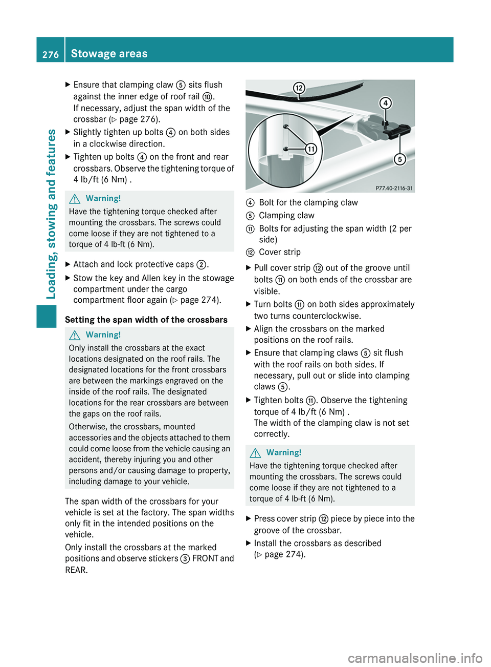
?Bolt for the clamping clawAClamping clawGBolts for adjusting the span width (2 per
side)HCover stripXPull cover strip H out of the groove until
bolts G on both ends of the crossbar are
visible.XTurn bolts G on both sides approximately
two turns counterclockwise.XAlign the crossbars on the marked
positions on the roof rails.XEnsure that clamping claws A sit flush
with the roof rails on both sides. If
necessary, pull out or slide into clamping
claws A.XTighten bolts G. Observe the tightening
torque of 4 lb/ft (6 Nm) .
The width of the clamping claw is not set
correctly.GWarning!
Have the tightening torque checked after
mounting the crossbars. The screws could
come loose if they are not tightened to a
torque of 4 lb-ft (6 Nm).
XPress cover strip H piece by piece into the
groove of the crossbar.XInstall the crossbars as described
( Y page 274).276Stowage areasLoading, stowing and features
BA 164.8 USA, CA Edition B 2011; 1; 2, en-USd2sboikeVersion: 3.0.3.52010-04-21T15:08:44+02:00 - Seite 276
Page 279 of 376
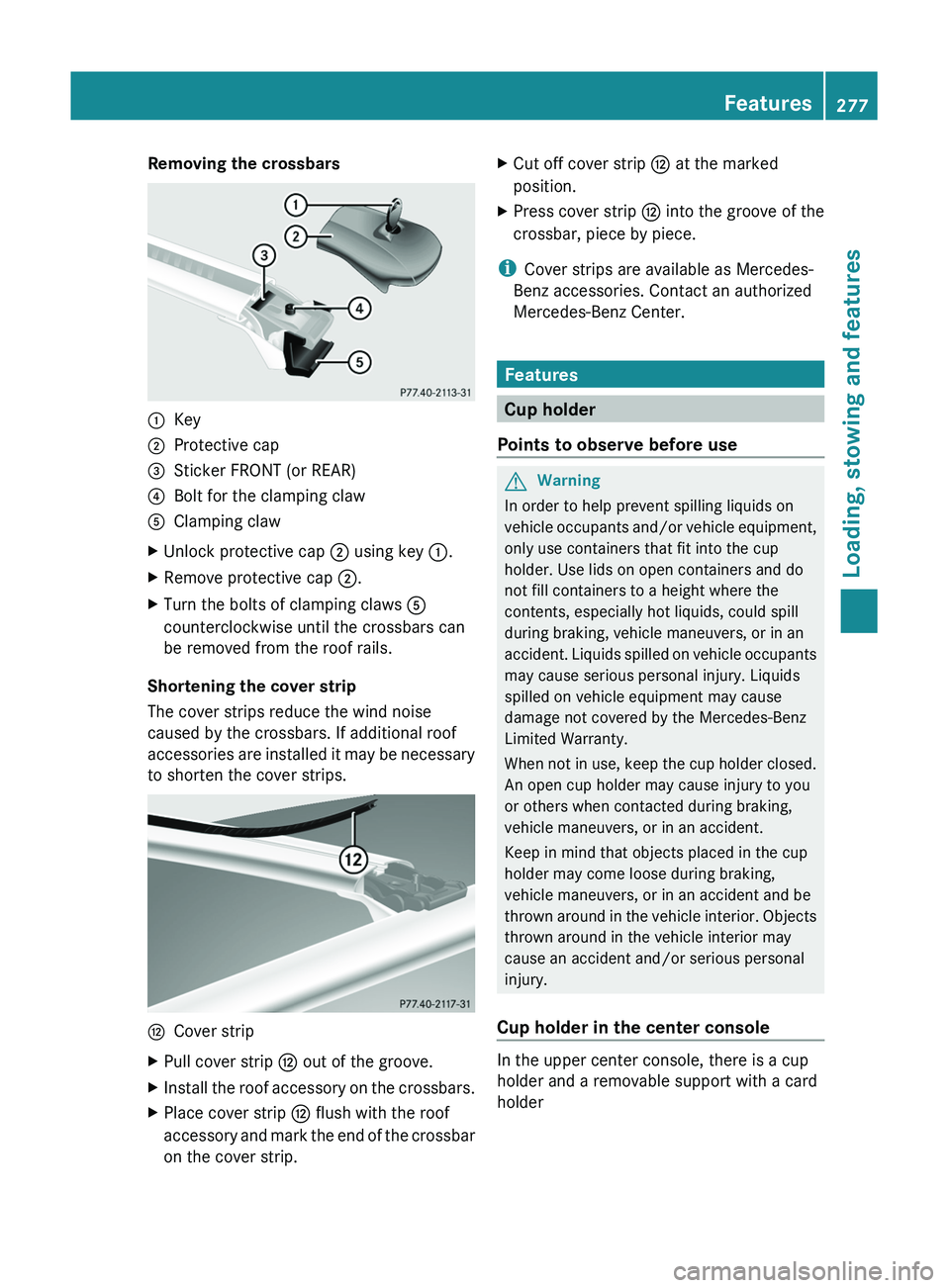
Removing the crossbars:Key;Protective cap=Sticker FRONT (or REAR)?Bolt for the clamping clawAClamping clawXUnlock protective cap ; using key :.XRemove protective cap ;.XTurn the bolts of clamping claws A
counterclockwise until the crossbars can
be removed from the roof rails.
Shortening the cover strip
The cover strips reduce the wind noise
caused by the crossbars. If additional roof
accessories are installed it may be necessary
to shorten the cover strips.
HCover stripXPull cover strip H out of the groove.XInstall the roof accessory on the crossbars.XPlace cover strip H flush with the roof
accessory and mark the end of the crossbar
on the cover strip.XCut off cover strip H at the marked
position.XPress cover strip H into the groove of the
crossbar, piece by piece.
i Cover strips are available as Mercedes-
Benz accessories. Contact an authorized
Mercedes-Benz Center.
Features
Cup holder
Points to observe before use
GWarning
In order to help prevent spilling liquids on
vehicle occupants and/or vehicle equipment,
only use containers that fit into the cup
holder. Use lids on open containers and do
not fill containers to a height where the
contents, especially hot liquids, could spill
during braking, vehicle maneuvers, or in an
accident. Liquids spilled on vehicle occupants
may cause serious personal injury. Liquids
spilled on vehicle equipment may cause
damage not covered by the Mercedes-Benz
Limited Warranty.
When not in use, keep the cup holder closed.
An open cup holder may cause injury to you
or others when contacted during braking,
vehicle maneuvers, or in an accident.
Keep in mind that objects placed in the cup
holder may come loose during braking,
vehicle maneuvers, or in an accident and be
thrown around in the vehicle interior. Objects
thrown around in the vehicle interior may
cause an accident and/or serious personal
injury.
Cup holder in the center console
In the upper center console, there is a cup
holder and a removable support with a card
holder
Features277Loading, stowing and featuresBA 164.8 USA, CA Edition B 2011; 1; 2, en-USd2sboikeVersion: 3.0.3.52010-04-21T15:08:44+02:00 - Seite 277Z
Page 280 of 376
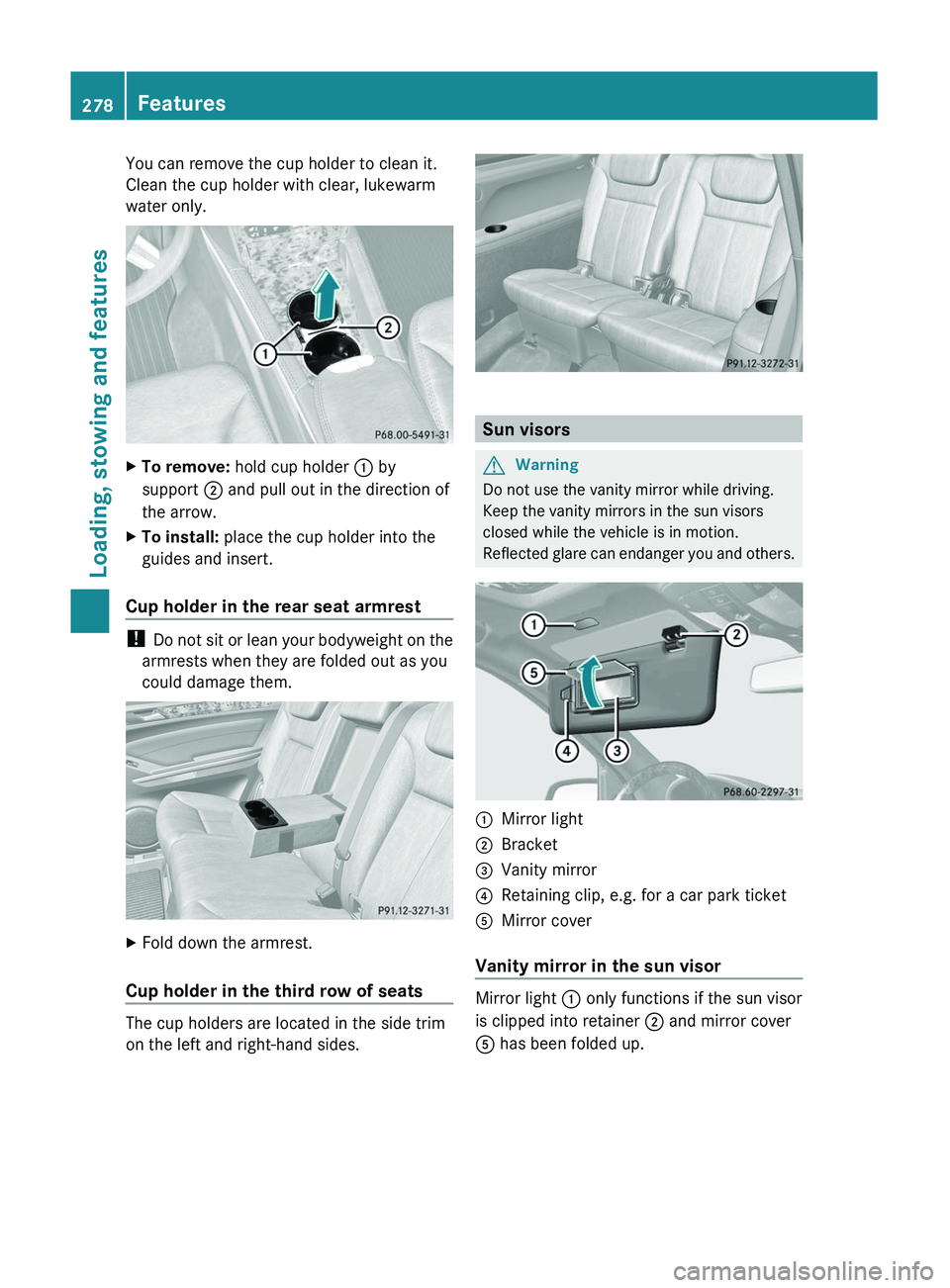
You can remove the cup holder to clean it.
Clean the cup holder with clear, lukewarm
water only.XTo remove: hold cup holder : by
support ; and pull out in the direction of
the arrow.XTo install: place the cup holder into the
guides and insert.
Cup holder in the rear seat armrest
! Do not sit or lean your bodyweight on the
armrests when they are folded out as you
could damage them.
XFold down the armrest.
Cup holder in the third row of seats
The cup holders are located in the side trim
on the left and right-hand sides.
Sun visors
GWarning
Do not use the vanity mirror while driving.
Keep the vanity mirrors in the sun visors
closed while the vehicle is in motion.
Reflected glare can endanger you and others.
:Mirror light;Bracket=Vanity mirror?Retaining clip, e.g. for a car park ticketAMirror cover
Vanity mirror in the sun visor
Mirror light : only functions if the sun visor
is clipped into retainer ; and mirror cover
A has been folded up.
278FeaturesLoading, stowing and features
BA 164.8 USA, CA Edition B 2011; 1; 2, en-USd2sboikeVersion: 3.0.3.52010-04-21T15:08:44+02:00 - Seite 278