MERCEDES-BENZ GL 2012 Owners Manual
Manufacturer: MERCEDES-BENZ, Model Year: 2012, Model line: GL, Model: MERCEDES-BENZ GL 2012Pages: 384, PDF Size: 15.71 MB
Page 211 of 384
lost and steering would no longer be possible.
The differential locks must therefore only be
activated off-road and only if activating the
other driving systems (4ETS, ESP ®
and LOW
Range off-road gear) is no longer sufficient.
Engaging the differential locks
! Pull away slowly when the differential
locks are activated.
Function or performance tests may only be
performed on a 2-axle dynamometer. If you
wish to operate the vehicle on such a
dynamometer, please consult an
authorized Mercedes-Benz Center
beforehand. You could otherwise damage
the drive train or the brake system.
Automatic mode
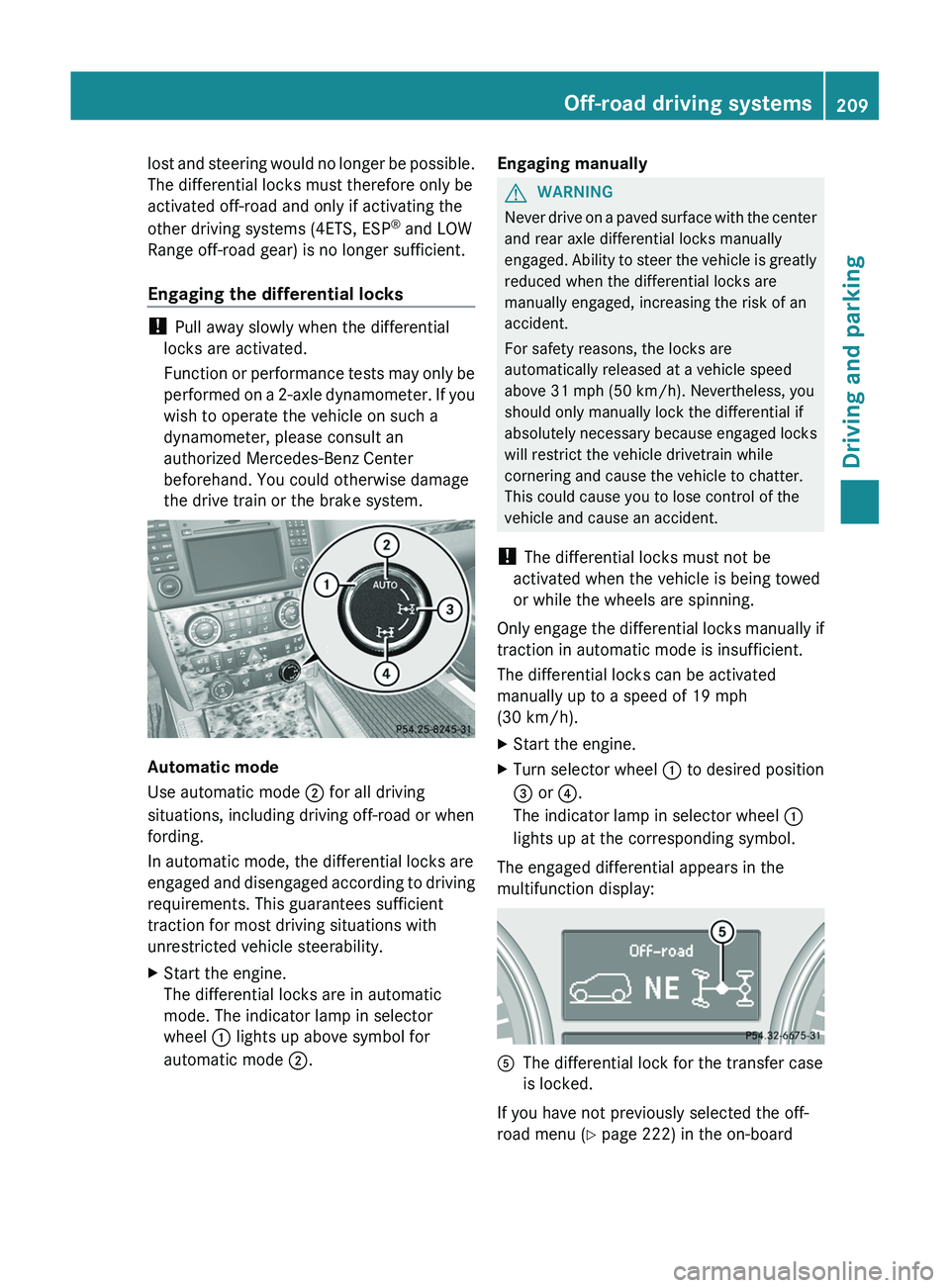
Use automatic mode ; for all driving
situations, including driving off-road or when
fording.
In automatic mode, the differential locks are
engaged and disengaged according to driving
requirements. This guarantees sufficient
traction for most driving situations with
unrestricted vehicle steerability.
XStart the engine.
The differential locks are in automatic
mode. The indicator lamp in selector
wheel : lights up above symbol for
automatic mode ;.Engaging manuallyGWARNING
Never drive on a paved surface with the center
and rear axle differential locks manually
engaged. Ability to steer the vehicle is greatly
reduced when the differential locks are
manually engaged, increasing the risk of an
accident.
For safety reasons, the locks are
automatically released at a vehicle speed
above 31 mph (50 km/h). Nevertheless, you
should only manually lock the differential if
absolutely necessary because engaged locks
will restrict the vehicle drivetrain while
cornering and cause the vehicle to chatter.
This could cause you to lose control of the
vehicle and cause an accident.
! The differential locks must not be
activated when the vehicle is being towed
or while the wheels are spinning.
Only engage the differential locks manually if
traction in automatic mode is insufficient.
The differential locks can be activated
manually up to a speed of 19 mph
(30 km/h).
XStart the engine.XTurn selector wheel : to desired position
= or ?.
The indicator lamp in selector wheel :
lights up at the corresponding symbol.
The engaged differential appears in the
multifunction display:
AThe differential lock for the transfer case
is locked.
If you have not previously selected the off-
road menu ( Y page 222) in the on-board
Off-road driving systems209Driving and parkingZ
Page 212 of 384
computer, the message disappears after
about five seconds.
The differential locks are not controlled
automatically. The steerability of the vehicle
is restricted considerably. Drive carefully and
accelerate gently for optimum traction.
! If the differential locks are activated
manually, the wheels scuff on the road
when cornering since the rotation
difference between the wheels is no longer
balanced out.
You can switch back to automatic mode at
any time. For safety reasons, the differential
locks are deactivated automatically at speeds
over 31 mph (50 km/h). If you stop the
vehicle and switch off the ignition for longer
than ten seconds, the differential locks
switch back to automatic mode.
Message in the multifunction display
Diff. lock system overheated.
Wait briefly.
The differential lock system has overheated
and briefly disengaged.XContinue driving.
The differential locks cool off and are soon
available once again.
Trailer towing
Notes on towing a trailer
Important safety notes
GWARNING
When towing a trailer, incorrect equipment
and driving style could cause you to lose
control of the vehicle.
Towing incorrectly or not observing this
Operator's Manual could lead to damage to
the vehicle and/or serious injuries. Observe
the following guidelines to ensure safe trailer
towing.
Contact a Mercedes-Benz Center if you need
further explanation of the information
contained in this Operator's Manual.
General information
R Only install an approved trailer coupling on
your vehicle.
Further information on availability and on
installation is available from any authorized
Mercedes-Benz Center.
R The bumpers of your vehicle are not
suitable for installing detachable trailer
couplings.
R Do not install hired trailer couplings or
other detachable trailer couplings on the
bumpers of your vehicle.
R To reduce the risk of damage to the ball
coupling, remove it from the ball coupling
recess when not in use.
Coupling up a trailer
GWARNING
While you are coupling or decoupling a trailer,
make sure nobody locks or unlocks the
vehicle and/or opens or closes doors or the
tailgate.
The vehicle's level could change and you
could endanger yourself and/or others as a
result.
Make sure that you do not operate the ADS
button or the vehicle level control system
when coupling/decoupling the trailer.
Observe the maximum permissible trailer
dimensions (width and length).
Most federal states and all Canadian
provinces require by law:
R safety chains between the towing vehicle
and the trailer. The chains should be cross-
wound under the trailer drawbar. They must
be fastened to the vehicle's trailer
coupling, not to the bumper or the axle.
210Trailer towingDriving and parking
Page 213 of 384
Allow for enough play in the chains to
facilitate turning tight corners.
R a separate brake system for certain types
of trailer.
R a safety switch for braked trailers. Check
the specific legal requirements applicable
to your federal state.
If the trailer detaches from the towing
vehicle, the safety switch applies the
trailer's brakes.
! Do not connect the trailer's brake system
(if featured) to the hydraulic brake system
of the towing vehicle, as the latter is
equipped with an anti-lock brake system.
Doing so will result in a loss of function of
the brake systems of both the vehicle and
the trailer.
i The vehicle's wiring harness features a
line to the brake indicator lamp.XMake sure that the automatic transmission
is set to position P.XApply the vehicle's parking brake.XStart the engine.XSelect highway level.XVehicles with the adaptive damping
system: set ADS to AUTO or COMF .XSwitch off the engine.XClose all doors and the tailgate.XCouple up the trailer.XEstablish all electrical connections.
i
Vehicles with the AIRMATIC package:
with a trailer attached, the vehicle will
always remain at highway level. When
coupling up a trailer, please observe the
following:
R if highway level has not been set
manually, the vehicle will automatically
sink to highway level as soon as it
reaches a speed of 5 mph (8 km/h).
R high-speed level is not available.
These restrictions apply to all accessories
powered through a connection to the trailer
power socket of your vehicle, e.g. a bicycle
carrier.
Towing a trailer
There are numerous legal requirements
concerning the towing of a trailer, e.g. speed
restrictions. Make sure that your vehicle/
trailer combination complies with the local
requirements not only in your area of
residence but also at any location to which
you are traveling. The police and local
authorities can provide reliable information.
Please observe the following when towing a
trailer:
R To acquaint yourself with driving with a
trailer and with the resulting changes to
handling, you should practice cornering,
stopping and reversing in a traffic-free
location.
R Before driving, check:
- the trailer tow hitch
- the safety switch for braked trailers
- the safety chains
- the electrical connections
- the lights
- the wheels
R Adjust the exterior mirrors to provide an
unobstructed view of the rear section of the
trailer.
R If the trailer features electronically
controlled brakes, pull away the vehicle/
trailer combination carefully, manually
brake using the brake controller, and check
the brakes for correct function.
R Secure any objects on the trailer to prevent
the cargo from slipping when the vehicle is
in motion.
R If you couple up a trailer, regularly check
the cargo for secure fastening and make
sure that the trailer lamps and (if
applicable) the trailer brakes are
functioning correctly.
R Bear in mind that the handling will be less
stable when towing a trailer than when
Trailer towing211Driving and parkingZ
Page 214 of 384
driving without one. Avoid sudden steering
movements.
R The vehicle/trailer combination is heavier,
accelerates more slowly, has a decreased
gradient climbing capability and a longer
braking distance.
It is more susceptible to side winds and
requires more careful steering.
R If possible, avoid abrupt braking. Depress
the brake pedal moderately at first, so that
the trailer can activate its own brakes. Then
increase the pressure on the brake pedal.
R If the automatic transmission continues to
shift back and forth between two gears
when driving up or downhill, restrict the
shift range. Select shift range 4, 3, 2, or 1.
A lower gear and lower speed reduce the
risk of engine failure.
R On long and steep gradients that are
difficult to drive down in shift range 1,
switch to the off-road drive program or
engage the LOW RANGE off-road gear.
R When driving downhill, shift to a lower gear
to utilize the engine's braking effect.
Avoid continuous brake application as this
may overheat the vehicle brakes and, if
installed, the trailer brakes.
R If the coolant temperature increases
dramatically while the air-conditioning
system is switched on, switch off the air-
conditioning system.
Coolant heat can additionally be dissipated
by opening the windows and by setting the
blower fan and the interior temperature to
maximum.
R When overtaking, pay particular attention
to the extended length of your vehicle/
trailer combination.
Due to the length of your vehicle/trailer
combination, you will have to travel an
additional distance beyond the vehicle you
are overtaking before returning to the
previous lane.Decoupling a trailerGWARNING
While you are coupling or decoupling a trailer,
make sure nobody locks or unlocks the
vehicle and/or opens or closes doors or the
tailgate.
The vehicle's level could change and you
could endanger yourself and/or others as a
result.
Make sure that you do not operate the ADS
button or the vehicle level control system
when coupling/decoupling the trailer.
XMake sure that the automatic transmission
is set to position P.XApply the vehicle's parking brake.XStart the engine.XClose all doors and the tailgate.XApply the trailer's parking brake.GWARNING
As soon as you disconnect the electrical
connection between the trailer and the
vehicle, the vehicle will lower. To help avoid
personal injury, make sure no one is near the
wheel housing or underneath the vehicle
before the electrical connection is
disconnected.
When you decouple the trailer, the vehicle is
temporarily raised because the springs are
relieved of load. Be especially careful during
this process, as you could otherwise injure
yourself and/or others. Make sure that any
persons remaining in the vehicle do not press
the switches for vehicle level control or the
ADS.
XRemove the trailer cable and decouple the
trailer.XSwitch off the engine.212Trailer towingDriving and parking
Page 215 of 384
Permissible trailer loads and drawbar
noseweights
Weight specifications
The Gross Trailer Weight (GTW) is the
combined weight of the trailer together with
the cargo and equipment loaded on the
trailer. Permissible gross weight: 7500 lb
(3402 kg).
The permissible Trailer drawbar Weight
Rating (TWR) is the maximum weight
permitted on the trailer drawbar: 600 lb
(272 kg) limit for Mercedes-Benz-approved
trailer couplings.
Loading a trailer
R When loading a trailer, please note that
neither the permissible gross trailer weight
nor the permissible Gross Vehicle Weight
Rating (GVWR) may be exceeded. The
permissible Gross Vehicle Weight Rating
(GVWR) is specified on the type plate
located on the B-pillar on the driver's side
of your vehicle.
You can find the maximum permissible
values on the type plates of your vehicle
and the trailer. Always observe the lowest
respective value when determining the
maximum weight with which you can load
the vehicle and the trailer.
R The drawbar noseweight acting on the ball
coupling has to be added to the rear axle
weight in order to prevent the permissible
Gross Axle Weight Rating (GAWR) from
being exceeded. The permissible Gross
Vehicle Weight Rating (GVWR) is specified
on the type plate located on the B-pillar on
the driver's side of your vehicle.
i Mercedes-Benz recommends loading the
trailer so that the drawbar noseweight
remains between 8% and 15% of the
permissible gross trailer weight.
i The weight of additional accessories,
passengers, and cargo reduces the
permissible trailer load and drawbar
noseweight for your vehicle.
Checking the vehicle and trailer weight
R To check that the weights of the towing
vehicle and the trailer comply with the
maximum permissible values, have the
vehicle/trailer combination (including the
driver, passengers, and cargo with a fully
laden trailer) weighed on a calibrated
weighbridge.
R Check the gross axle weight rating of the
front and rear axle, the Gross Trailer Weight
(GTW), and the drawbar noseweight.
Trailer power supply
The trailer power socket of your vehicle is
designed for connecting the 7-pin connector
supplied as part of the Mercedes-Benz-
approved trailer coupling.
i Depending on your trailer, you may need
an adapter to connect your trailer to the
vehicle.
Further information is available from any
authorized Mercedes-Benz Center.
Trailer towing213Driving and parkingZ
Page 216 of 384

214
Page 217 of 384

Useful information ............................216
Important safety notes ....................216
Displays and operation ....................216
Menus and submenus ......................219
Display messages ............................. 232
Warning and indicator lamps in the
instrument cluster ............................258215On-board computer and displays
Page 218 of 384
Useful information
i This Operator's Manual describes all
models and all standard and optional
equipment of your vehicle available at the
time of publication of the Operator's
Manual. Country-specific differences are
possible. Please note that your vehicle may
not be equipped with all features
described. This also applies to safety-
related systems and functions.
i Please read the information on qualified
specialist workshops ( Y page 24).
Important safety notes
You will find an illustration of the instrument
cluster in the "At a glance" section
( Y page 29).
GWARNING
A driver's attention to the road and traffic
conditions must always be his/her primary
focus when driving.
For your safety and the safety of others,
selecting features through the multifunction
steering wheel should only be done by the
driver when traffic and road conditions permit
it to be done safely.
Bear in mind that at a speed of just 30 mph
(approximately 50 km/h ), your vehicle is
covering a distance of 44 feet (approximately
14 m) every second.
GWARNING
No messages will be displayed if either the
instrument cluster or the multifunction
display is inoperative.
As a result, you will not be able to see
information about your driving conditions,
such as
R speed
R outside temperature
R warning/indicator lamps
Rmalfunction/warning messages
R failure of any systems
Driving characteristics may be impaired.
If you must continue to drive, do so with added
caution. Contact an authorized Mercedes-
Benz Center as soon as possible.GWARNING
Malfunction and warning messages are only
indicated for certain systems and are
intentionally not very detailed. The
malfunction and warning messages are
simply a reminder with respect to the
operation of certain systems. They do not
replace the owner's and/or driver's
responsibility to maintain the vehicle's
operating safety. Have all required
maintenance and safety checks performed on
the vehicle. Bring the vehicle to an authorized
Mercedes-Benz Center to address the
malfunction and warning messages.
Displays and operation
Tachometer
The red band in the tachometer indicates the
engine's overrevving range.
! Do not drive in the overrevving range, as
this could damage the engine.
The fuel supply is interrupted to protect the
engine when the red band is reached.
Outside temperature display
The outside temperature display is in the
multifunction display ( Y page 218).
GWARNING
The outside temperature indicator is not
designed to serve as an ice-warning device
and is therefore unsuitable for that purpose.
Indicated temperatures just above the
freezing point do not guarantee that the road
216Displays and operationOn-board computer and displays
Page 219 of 384
surface is free of ice. The road may still be icy,
especially in wooded areas or on bridges.
Changes in the outside temperature are
displayed after a short delay.
Speedometer with segments
The segments in the speedometer indicate
which speed range is available.
DISTRONIC ( Y page 182) activated:
One or two segments in the set speed range
light up.
DISTRONIC detects a vehicle in front:
The segments between the speed of the
vehicle in front and the stored speed light up.
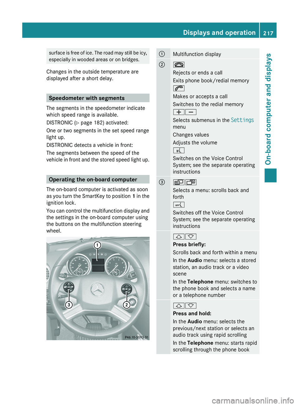
Operating the on-board computer
The on-board computer is activated as soon
as you turn the SmartKey to position 1 in the
ignition lock.
You can control the multifunction display and
the settings in the on-board computer using
the buttons on the multifunction steering
wheel.
:Multifunction display;~
Rejects or ends a call
Exits phone book/redial memory
6
Makes or accepts a call
Switches to the redial memory
WX
Selects submenus in the Settings
menu
Changes values
Adjusts the volume
?
Switches on the Voice Control
System; see the separate operating
instructions=VU
Selects a menu: scrolls back and
forth
A
Switches off the Voice Control
System; see the separate operating
instructions&*
Press briefly:
Scrolls back and forth within a menu
In the Audio menu: selects a stored
station, an audio track or a video
scene
In the Telephone menu: switches to
the phone book and selects a name
or a telephone number&*
Press and hold:
In the Audio menu: selects the
previous/next station or selects an
audio track using rapid scrolling
In the Telephone menu: starts rapid
scrolling through the phone bookDisplays and operation217On-board computer and displaysZ
Page 220 of 384
Multifunction display
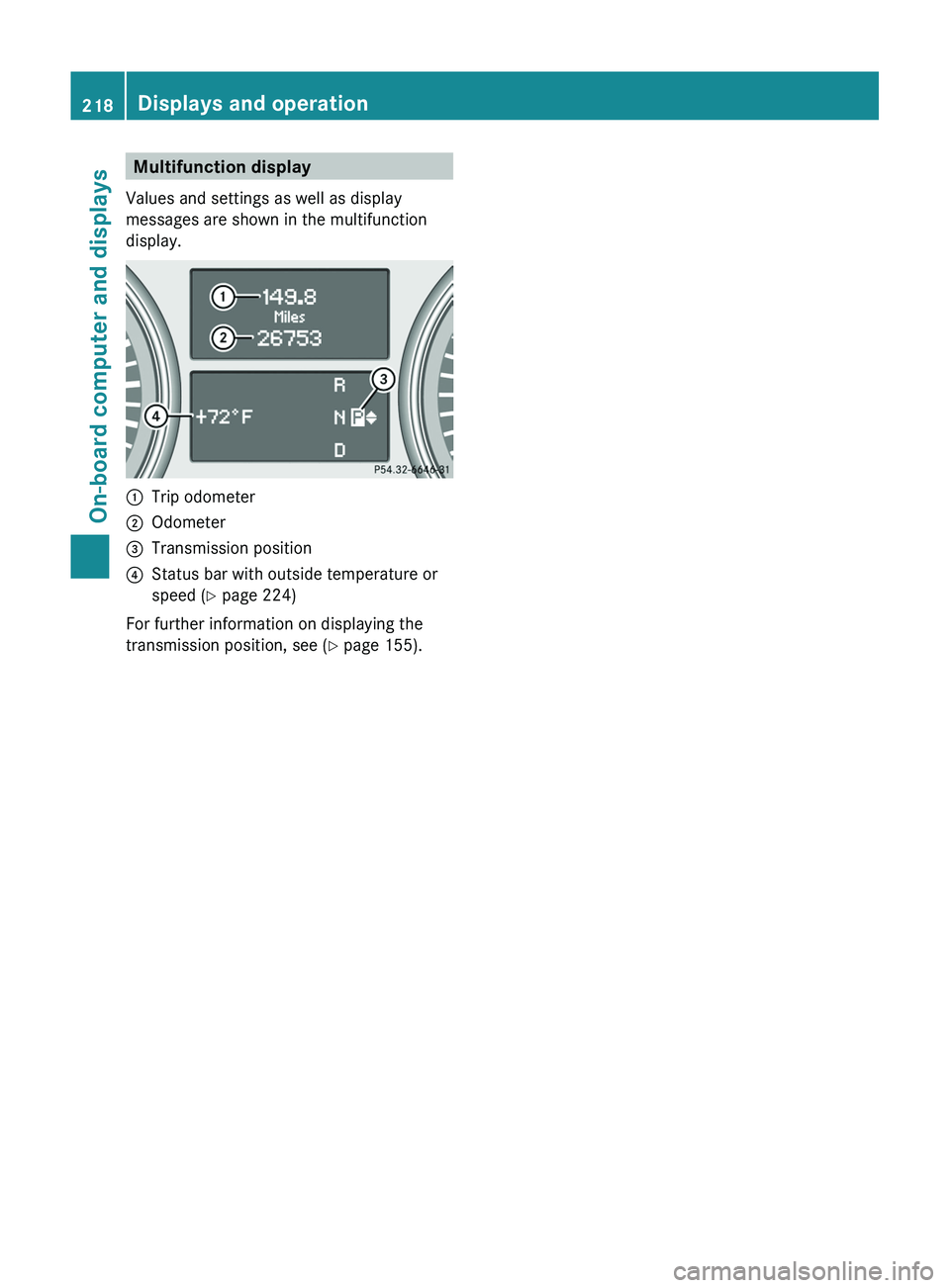
Values and settings as well as display
messages are shown in the multifunction
display.:Trip odometer;Odometer=Transmission position?Status bar with outside temperature or
speed ( Y page 224)
For further information on displaying the
transmission position, see ( Y page 155).
218Displays and operationOn-board computer and displays