width MERCEDES-BENZ GL 2012 Owners Manual
[x] Cancel search | Manufacturer: MERCEDES-BENZ, Model Year: 2012, Model line: GL, Model: MERCEDES-BENZ GL 2012Pages: 384, PDF Size: 15.71 MB
Page 9 of 384
Convenience closing feature .............. 91
Convenience opening feature ............ 91
Coolant (engine) Checking the level .........................303
Display message ............................ 244
Notes ............................................. 376
Temperature gauge ........................ 220
Cooling
see Climate control
Cornering light (display message) ... 241
Crash-responsive emergency
lighting ............................................... 123
Crossbar Installing ........................................ 278
Setting the span width ...................280
Cruise control
Cruise control lever .......................180
Deactivating ................................... 181
Display message ............................ 250
Driving system ............................... 179
Function/notes ............................. 179
Important safety notes ..................179
LIM indicator lamp .........................180
Setting a speed .............................. 181
Storing and maintaining current
speed ............................................. 180
Cup holder
Center console .............................. 282
Important safety notes ..................282
Rear compartment .........................282
third row of seats ........................... 282
Customer Assistance Center (CAC) ... 24
Customer Relations Department ....... 25
D
Dashboard see Cockpit
Date (on-board computer) ................ 224
Daytime running lamp mode see Daytime running lamps
Daytime running lamps
Display message ............................ 243
Switching on/off (on-board
computer) ...................................... 224
Switching on/off (switch) ..............119
DEF
Adding ........................................... 164
Display message ............................ 247
Delayed switch-off
Exterior lighting (on-board
computer) ...................................... 225
Interior lighting .............................. 226
Diesel particle filter .......................... 169
Differential locks Display message ............................ 249
Notes/function .............................. 208
Digital speedometer
Displaying ...................................... 220
Setting the unit (on-board
computer) ...................................... 224
DIRECT SELECT lever
see Automatic transmission
Display (cleaning instructions) ........ 310
Display messages Calling up (on-board computer) .....232
Driving systems ............................. 248
Engine ............................................ 244
General notes ................................ 232
Hiding (on-board computer) ...........232
Key ................................................ 256
KEYLESS-GO .................................. 256
Lights ............................................. 241
Safety systems .............................. 233
Service interval display ..................305
Tires ............................................... 252
Vehicle ........................................... 254
Distance recorder ............................. 220
see Odometer
see Trip odometer
Distance warning (warning lamp) .... 265
Distance warning function
(vehicles with DISTRONIC) Activating/deactivating (on-
board computer) ............................ 228
Notes ............................................... 72
DISTRONIC
Deactivating ................................... 187
Display message ............................ 251
Displays in the multifunction
display ........................................... 187
Driving tips .................................... 188
Important safety notes ..................182
Notes/function .............................. 182Index7
Page 59 of 384
portion of the seat belt under your arm. For
this purpose, you can adjust the height of
the seat belt outlet.
R Position the lap belt as low as possible on
your hips and not across the abdomen. If
the lap belt is positioned across your
abdomen, it could cause serious injuries in
a crash.
R Never wear seat belts over rigid or
breakable objects in or on your clothing,
such as eyeglasses, pens, keys etc., as
these might cause injuries.
R Make sure the seat belt is always fitted
snugly. Take special care of this when
wearing loose clothing.
R Never use a seat belt for more than one
person at a time. Do not fasten a seat belt
around a person and another person or
other objects at the same time.
R Seat belts should not be worn twisted. In a
crash, you would not have the full width of
the seat belt to distribute impact forces.
The twisted seat belt against your body
could cause injuries.
R Pregnant women should also always use a
lap-shoulder belt. The lap belt portion
should be positioned as low as possible on
the hips to avoid any possible pressure on
the abdomen.
R Place the seat backrest in a position that is
as upright as possible.
R Check your seat belt during travel to make
sure it is properly positioned.
R Never place your feet on the instrument
panel, dashboard, or on the seat. Always
keep both feet on the floor in front of the
seat.
R When using a seat belt to secure infant
restraints, toddler restraints, or children in
booster seats, always follow the child seat
manufacturer's instructions.GWARNING
Do not pass seat belts over sharp edges. They
could tear.
Do not allow the seat belt to get caught in the
door or in the seat adjustment mechanism.
This could damage the seat belt.
Never attempt to make modifications to seat
belts. This could impair the effectiveness of
the seat belts.
Fastening seat beltsGWARNING
According to accident statistics, children are
safer when properly restrained on the rear
seats than on the front-passenger seat. Thus,
we strongly recommend that children be
placed in the rear seat whenever possible.
Regardless of seating position, children 12
years old and under must be seated and
properly secured in an appropriately sized
child restraint system or booster seat
recommended for the size and weight of the
child. For additional information, see the
"Children in the vehicle" section.
A child's risk of serious or fatal injuries is
significantly increased if the child restraints
are not properly secured in the vehicle and/
or the child is not properly secured in the child
restraint.
GWARNING
Canada only: children 12 years old and under
may ride on the front seat if a BabySmart™
compatible child restraint system is installed
on the front-passenger seat. Use only
Mercedes-Benz approved BabySmart™
compatible child restraint systems. A
BabySmart™ compatible child restraint
system will deactivate the front-passenger
front air bag when installed correctly. The
front-passenger front air bag will not be
deactivated if the child restraint systems that
are installed are not BabySmart™ compatible
or if BabySmart™ compatible child restraint
systems are not installed correctly. If the
front-passenger front air bag is deployed in a
collision, the child will be struck by the air bag.
If this happens, serious or fatal injury will
result.
Occupant safety57SafetyZ
Page 191 of 384
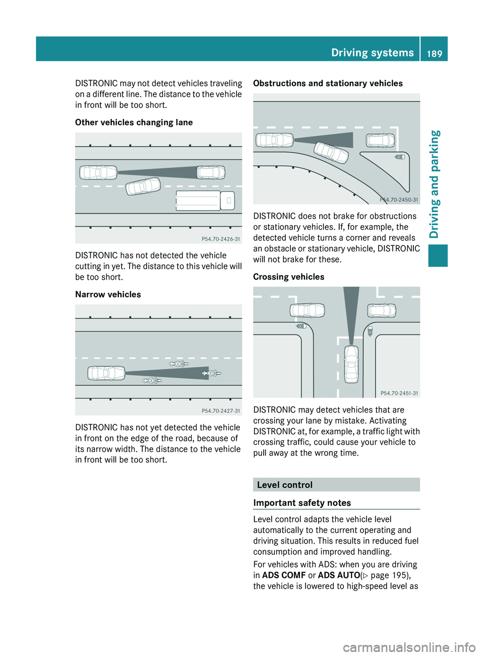
DISTRONIC may not detect vehicles traveling
on a different line. The distance to the vehicle
in front will be too short.
Other vehicles changing lane
DISTRONIC has not detected the vehicle
cutting in yet. The distance to this vehicle will
be too short.
Narrow vehicles
DISTRONIC has not yet detected the vehicle
in front on the edge of the road, because of
its narrow width. The distance to the vehicle
in front will be too short.
Obstructions and stationary vehicles
DISTRONIC does not brake for obstructions
or stationary vehicles. If, for example, the
detected vehicle turns a corner and reveals
an obstacle or stationary vehicle, DISTRONIC
will not brake for these.
Crossing vehicles
DISTRONIC may detect vehicles that are
crossing your lane by mistake. Activating
DISTRONIC at, for example, a traffic light with
crossing traffic, could cause your vehicle to
pull away at the wrong time.
Level control
Important safety notes
Level control adapts the vehicle level
automatically to the current operating and
driving situation. This results in reduced fuel
consumption and improved handling.
For vehicles with ADS: when you are driving
in ADS COMF or ADS AUTO (Y page 195),
the vehicle is lowered to high-speed level as
Driving systems189Driving and parkingZ
Page 203 of 384
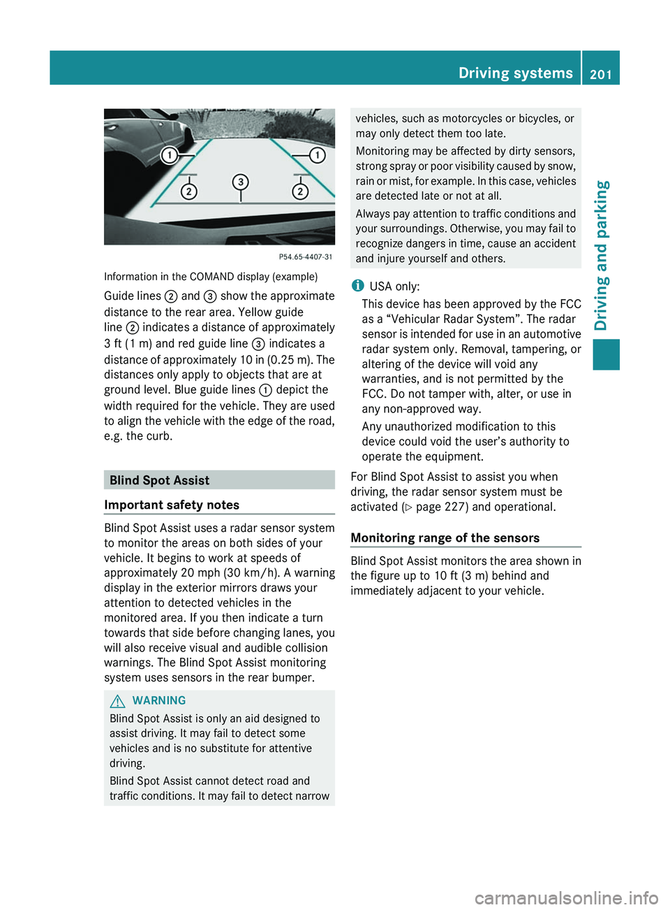
Information in the COMAND display (example)
Guide lines ; and = show the approximate
distance to the rear area. Yellow guide
line ; indicates a distance of approximately
3 ft (1 m) and red guide line = indicates a
distance of approximately 10 in (0.25 m). The
distances only apply to objects that are at
ground level. Blue guide lines : depict the
width required for the vehicle. They are used
to align the vehicle with the edge of the road,
e.g. the curb.
Blind Spot Assist
Important safety notes
Blind Spot Assist uses a radar sensor system
to monitor the areas on both sides of your
vehicle. It begins to work at speeds of
approximately 20 mph (30 km/h). A warning
display in the exterior mirrors draws your
attention to detected vehicles in the
monitored area. If you then indicate a turn
towards that side before changing lanes, you
will also receive visual and audible collision
warnings. The Blind Spot Assist monitoring
system uses sensors in the rear bumper.
GWARNING
Blind Spot Assist is only an aid designed to
assist driving. It may fail to detect some
vehicles and is no substitute for attentive
driving.
Blind Spot Assist cannot detect road and
traffic conditions. It may fail to detect narrow
vehicles, such as motorcycles or bicycles, or
may only detect them too late.
Monitoring may be affected by dirty sensors,
strong spray or poor visibility caused by snow,
rain or mist, for example. In this case, vehicles
are detected late or not at all.
Always pay attention to traffic conditions and
your surroundings. Otherwise, you may fail to
recognize dangers in time, cause an accident
and injure yourself and others.
i USA only:
This device has been approved by the FCC
as a “Vehicular Radar System”. The radar
sensor is intended for use in an automotive
radar system only. Removal, tampering, or
altering of the device will void any
warranties, and is not permitted by the
FCC. Do not tamper with, alter, or use in
any non-approved way.
Any unauthorized modification to this
device could void the user’s authority to
operate the equipment.
For Blind Spot Assist to assist you when
driving, the radar sensor system must be
activated ( Y page 227) and operational.
Monitoring range of the sensors
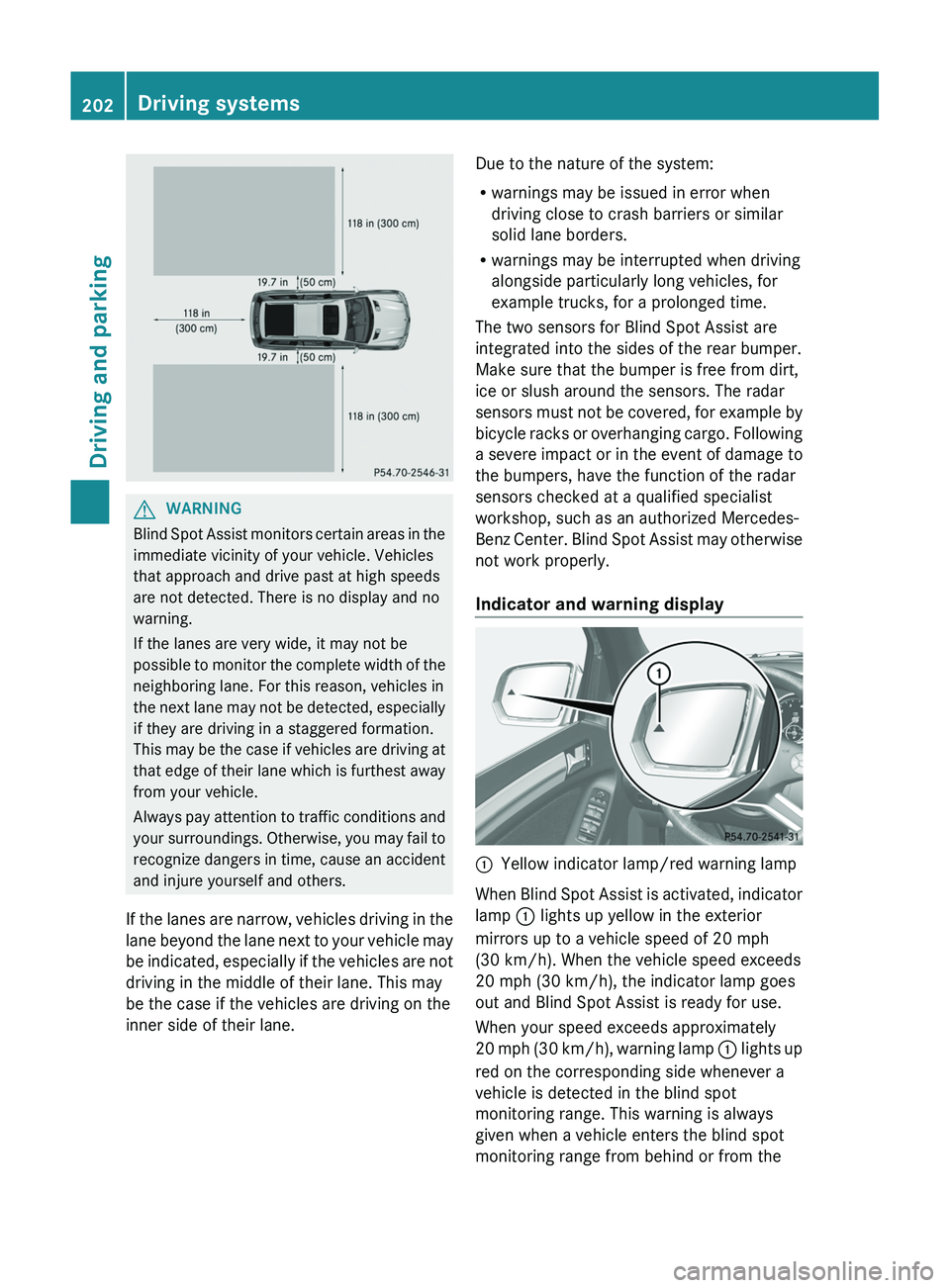
Blind Spot Assist monitors the area shown in
the figure up to 10 ft (3 m) behind and
immediately adjacent to your vehicle.
Driving systems201Driving and parkingZ
Page 204 of 384
GWARNING
Blind Spot Assist monitors certain areas in the
immediate vicinity of your vehicle. Vehicles
that approach and drive past at high speeds
are not detected. There is no display and no
warning.
If the lanes are very wide, it may not be
possible to monitor the complete width of the
neighboring lane. For this reason, vehicles in
the next lane may not be detected, especially
if they are driving in a staggered formation.
This may be the case if vehicles are driving at
that edge of their lane which is furthest away
from your vehicle.
Always pay attention to traffic conditions and
your surroundings. Otherwise, you may fail to
recognize dangers in time, cause an accident
and injure yourself and others.
If the lanes are narrow, vehicles driving in the
lane beyond the lane next to your vehicle may
be indicated, especially if the vehicles are not
driving in the middle of their lane. This may
be the case if the vehicles are driving on the
inner side of their lane.
Due to the nature of the system:
R warnings may be issued in error when
driving close to crash barriers or similar
solid lane borders.
R warnings may be interrupted when driving
alongside particularly long vehicles, for
example trucks, for a prolonged time.
The two sensors for Blind Spot Assist are
integrated into the sides of the rear bumper.
Make sure that the bumper is free from dirt,
ice or slush around the sensors. The radar
sensors must not be covered, for example by
bicycle racks or overhanging cargo. Following
a severe impact or in the event of damage to
the bumpers, have the function of the radar
sensors checked at a qualified specialist
workshop, such as an authorized Mercedes-
Benz Center. Blind Spot Assist may otherwise
not work properly.
Indicator and warning display:Yellow indicator lamp/red warning lamp
When Blind Spot Assist is activated, indicator
lamp : lights up yellow in the exterior
mirrors up to a vehicle speed of 20 mph
(30 km/h). When the vehicle speed exceeds
20 mph (30 km/h), the indicator lamp goes
out and Blind Spot Assist is ready for use.
When your speed exceeds approximately
20 mph (30 km/h), warning lamp : lights up
red on the corresponding side whenever a
vehicle is detected in the blind spot
monitoring range. This warning is always
given when a vehicle enters the blind spot
monitoring range from behind or from the
202Driving systemsDriving and parking
Page 212 of 384
computer, the message disappears after
about five seconds.
The differential locks are not controlled
automatically. The steerability of the vehicle
is restricted considerably. Drive carefully and
accelerate gently for optimum traction.
! If the differential locks are activated
manually, the wheels scuff on the road
when cornering since the rotation
difference between the wheels is no longer
balanced out.
You can switch back to automatic mode at
any time. For safety reasons, the differential
locks are deactivated automatically at speeds
over 31 mph (50 km/h). If you stop the
vehicle and switch off the ignition for longer
than ten seconds, the differential locks
switch back to automatic mode.
Message in the multifunction display
Diff. lock system overheated.
Wait briefly.
The differential lock system has overheated
and briefly disengaged.XContinue driving.
The differential locks cool off and are soon
available once again.
Trailer towing
Notes on towing a trailer
Important safety notes
GWARNING
When towing a trailer, incorrect equipment
and driving style could cause you to lose
control of the vehicle.
Towing incorrectly or not observing this
Operator's Manual could lead to damage to
the vehicle and/or serious injuries. Observe
the following guidelines to ensure safe trailer
towing.
Contact a Mercedes-Benz Center if you need
further explanation of the information
contained in this Operator's Manual.
General information
R Only install an approved trailer coupling on
your vehicle.
Further information on availability and on
installation is available from any authorized
Mercedes-Benz Center.
R The bumpers of your vehicle are not
suitable for installing detachable trailer
couplings.
R Do not install hired trailer couplings or
other detachable trailer couplings on the
bumpers of your vehicle.
R To reduce the risk of damage to the ball
coupling, remove it from the ball coupling
recess when not in use.
Coupling up a trailer
GWARNING
While you are coupling or decoupling a trailer,
make sure nobody locks or unlocks the
vehicle and/or opens or closes doors or the
tailgate.
The vehicle's level could change and you
could endanger yourself and/or others as a
result.
Make sure that you do not operate the ADS
button or the vehicle level control system
when coupling/decoupling the trailer.
Observe the maximum permissible trailer
dimensions (width and length).
Most federal states and all Canadian
provinces require by law:
R safety chains between the towing vehicle
and the trailer. The chains should be cross-
wound under the trailer drawbar. They must
be fastened to the vehicle's trailer
coupling, not to the bumper or the axle.
210Trailer towingDriving and parking
Page 283 of 384
XPull out cover strip H from the groove until
bolts G become visible on both ends of the
crossbar.XTurn bolts G counter-clockwise on both
sides by approx. two turns.XPlace the crossbars on the marked points
on the roof rails.XEnsure that clamping bracket A locks
flush with the roof rails on both sides. If
necessary, pull it out or push it into
clamping brackets A.XTighten bolts G. Maintain a tightening
torque of 4 lb-ft (6 Nm) .
The width of the clamping bracket is set
correctly.GWARNING
Have the tightening torque checked after
mounting the crossbars. The screws could
come loose if they are not tightened to a
torque of 4 lb-ft (6 Nm).
XPress cover strip H into the groove of the
crossbar bit by bit.XInstall the crossbars as described
( Y page 278).
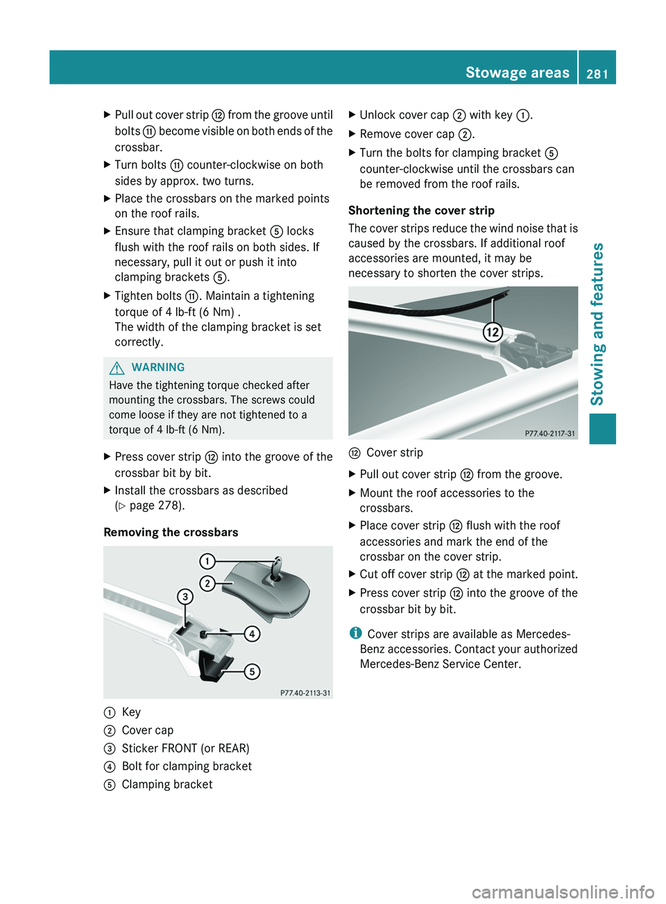
Removing the crossbars
:Key;Cover cap=Sticker FRONT (or REAR)?Bolt for clamping bracketAClamping bracketXUnlock cover cap ; with key :.XRemove cover cap ;.XTurn the bolts for clamping bracket A
counter-clockwise until the crossbars can
be removed from the roof rails.
Shortening the cover strip
The cover strips reduce the wind noise that is
caused by the crossbars. If additional roof
accessories are mounted, it may be
necessary to shorten the cover strips.
HCover stripXPull out cover strip H from the groove.XMount the roof accessories to the
crossbars.XPlace cover strip H flush with the roof
accessories and mark the end of the
crossbar on the cover strip.XCut off cover strip H at the marked point.XPress cover strip H into the groove of the
crossbar bit by bit.
i Cover strips are available as Mercedes-
Benz accessories. Contact your authorized
Mercedes-Benz Service Center.
Stowage areas281Stowing and featuresZ
Page 341 of 384
Notes on regularly inspecting wheels
and tiresGWARNING
Regularly check the tires for damage.
Damaged tires can cause tire inflation
pressure loss. As a result, you could lose
control of your vehicle.
Worn, old tires can cause accidents. If the tire
tread is worn to minimum tread depth, or if
the tires have sustained damage, replace
them.
R Regularly check the wheels and tires of
your vehicle for damage (e.g. cuts,
punctures, tears, bulges on tires and
deformation or cracks or severe corrosion
on wheels) at least once a month, as well
as after driving off-road or on rough roads.
Damaged wheels can cause a loss of tire
pressure.
R Regularly check the tire tread depth and
the condition of the tread across the whole
width of the tire (Y page 339). If necessary,
turn the front wheels to full lock in order to
inspect the inner side of the tire surface.
R All wheels must have a valve cap to protect
the valve against dirt and moisture. Do not
mount anything onto the valve (such as tire
pressure monitoring systems) other than
the standard valve cap or other valve caps
approved by Mercedes-Benz for your
vehicle.
R Regularly check the pressure of all the tires
including the emergency spare wheel or the
spare wheel, particularly prior to long trips,
and correct the pressure as necessary
( Y page 341).
Tire tread
GWARNING
Although the applicable federal motor vehicle
safety laws consider a tire to be worn when
the tread wear indicators (TWI) become
visible at approximately 1
/ 16 in (1.6 mm), we
recommend that you do not allow your tires
to wear down to that level. As tread depth
approaches 1
/ 8 in (3 mm), the adhesion
properties on a wet road are sharply reduced.
Depending upon the weather and/or road
surface (conditions), the tire traction varies
widely.
Do not use tires that are excessively worn as
the tire traction on wet road surfaces
decreases significantly when the tread depth
is less than 1
/ 8 inch (3 mm).
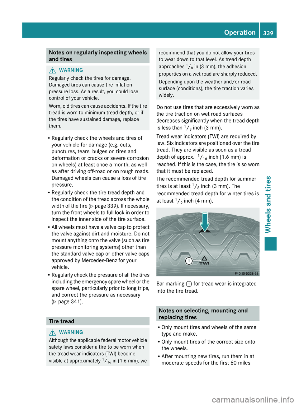
Tread wear indicators (TWI) are required by
law. Six indicators are positioned over the tire
tread. They are visible as soon as a tread
depth of approx. 1
/ 16 inch (1.6 mm) is
reached. If this is the case, the tire is so worn
that it must be replaced.
The recommended tread depth for summer
tires is at least 1
/ 8 inch (3 mm). The
recommended tread depth for winter tires is
at least 1
/ 6 inch (4 mm).
Bar marking
: for tread wear is integrated
into the tire tread.
Notes on selecting, mounting and
replacing tires
R Only mount tires and wheels of the same
type and make.
R Only mount tires of the correct size onto
the wheels.
R After mounting new tires, run them in at
moderate speeds for the first 60 miles
Operation339Wheels and tiresZ
Page 356 of 384
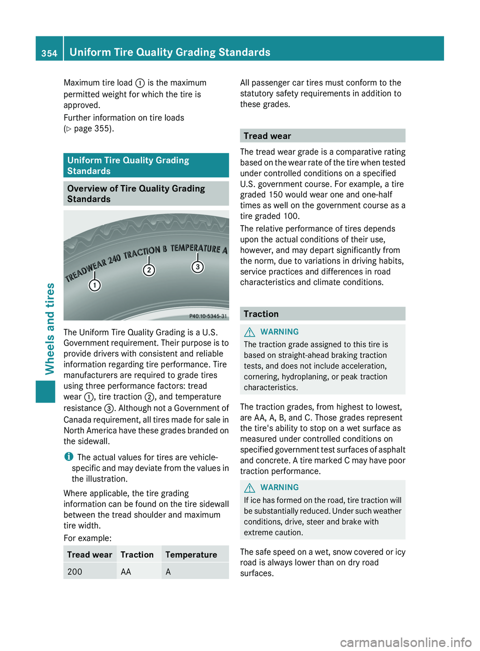
Maximum tire load : is the maximum
permitted weight for which the tire is
approved.
Further information on tire loads
( Y page 355).
Uniform Tire Quality Grading
Standards
Overview of Tire Quality Grading
Standards
The Uniform Tire Quality Grading is a U.S.
Government requirement. Their purpose is to
provide drivers with consistent and reliable
information regarding tire performance. Tire
manufacturers are required to grade tires
using three performance factors: tread
wear :, tire traction ;, and temperature
resistance =. Although not a Government of
Canada requirement, all tires made for sale in
North America have these grades branded on
the sidewall.
i The actual values for tires are vehicle-
specific and may deviate from the values in
the illustration.
Where applicable, the tire grading
information can be found on the tire sidewall
between the tread shoulder and maximum
tire width.
For example:
Tread wearTractionTemperature200AAAAll passenger car tires must conform to the
statutory safety requirements in addition to
these grades.
Tread wear
The tread wear grade is a comparative rating
based on the wear rate of the tire when tested
under controlled conditions on a specified
U.S. government course. For example, a tire
graded 150 would wear one and one-half
times as well on the government course as a
tire graded 100.
The relative performance of tires depends
upon the actual conditions of their use,
however, and may depart significantly from
the norm, due to variations in driving habits,
service practices and differences in road
characteristics and climate conditions.
Traction
GWARNING
The traction grade assigned to this tire is
based on straight-ahead braking traction
tests, and does not include acceleration,
cornering, hydroplaning, or peak traction
characteristics.
The traction grades, from highest to lowest,
are AA, A, B, and C. Those grades represent
the tire's ability to stop on a wet surface as
measured under controlled conditions on
specified government test surfaces of asphalt
and concrete. A tire marked C may have poor
traction performance.
GWARNING
If ice has formed on the road, tire traction will
be substantially reduced. Under such weather
conditions, drive, steer and brake with
extreme caution.
The safe speed on a wet, snow covered or icy
road is always lower than on dry road
surfaces.
354Uniform Tire Quality Grading StandardsWheels and tires
Page 358 of 384
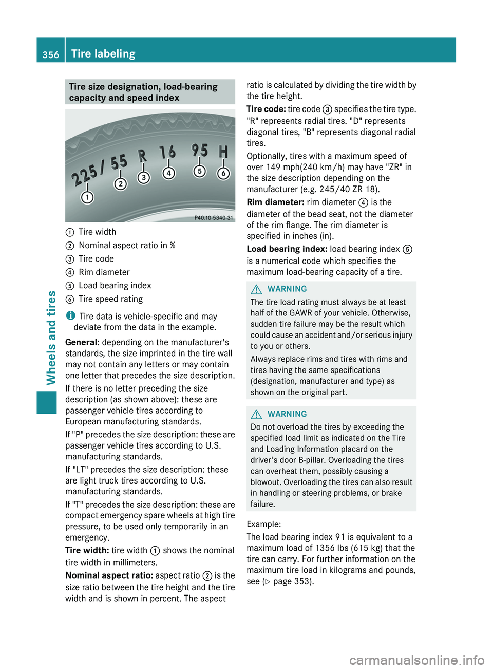
Tire size designation, load-bearing
capacity and speed index:Tire width;Nominal aspect ratio in %=Tire code?Rim diameterALoad bearing indexBTire speed rating
i Tire data is vehicle-specific and may
deviate from the data in the example.
General: depending on the manufacturer's
standards, the size imprinted in the tire wall
may not contain any letters or may contain
one letter that precedes the size description.
If there is no letter preceding the size
description (as shown above): these are
passenger vehicle tires according to
European manufacturing standards.
If "P" precedes the size description: these are
passenger vehicle tires according to U.S.
manufacturing standards.
If "LT" precedes the size description: these
are light truck tires according to U.S.
manufacturing standards.
If "T" precedes the size description: these are
compact emergency spare wheels at high tire
pressure, to be used only temporarily in an
emergency.
Tire width: tire width : shows the nominal
tire width in millimeters.
Nominal aspect ratio: aspect ratio ; is the
size ratio between the tire height and the tire
width and is shown in percent. The aspect
ratio is calculated by dividing the tire width by
the tire height.
Tire code: tire code = specifies the tire type.
"R" represents radial tires. "D" represents
diagonal tires, "B" represents diagonal radial
tires.
Optionally, tires with a maximum speed of
over 149 mph(240 km/h) may have "ZR" in
the size description depending on the
manufacturer (e.g. 245/40 ZR 18).
Rim diameter: rim diameter ? is the
diameter of the bead seat, not the diameter
of the rim flange. The rim diameter is
specified in inches (in).
Load bearing index: load bearing index A
is a numerical code which specifies the
maximum load-bearing capacity of a tire.GWARNING
The tire load rating must always be at least
half of the GAWR of your vehicle. Otherwise,
sudden tire failure may be the result which
could cause an accident and/or serious injury
to you or others.
Always replace rims and tires with rims and
tires having the same specifications
(designation, manufacturer and type) as
shown on the original part.
GWARNING
Do not overload the tires by exceeding the
specified load limit as indicated on the Tire
and Loading Information placard on the
driver's door B-pillar. Overloading the tires
can overheat them, possibly causing a
blowout. Overloading the tires can also result
in handling or steering problems, or brake
failure.
Example:
The load bearing index 91 is equivalent to a
maximum load of 1356 lbs (615 kg) that the
tire can carry. For further information on the
maximum tire load in kilograms and pounds,
see ( Y page 353).
356Tire labelingWheels and tires