Tailgate MERCEDES-BENZ GL-Class 2015 X166 Owner's Guide
[x] Cancel search | Manufacturer: MERCEDES-BENZ, Model Year: 2015, Model line: GL-Class, Model: MERCEDES-BENZ GL-Class 2015 X166Pages: 462, PDF Size: 9.09 MB
Page 271 of 462

using the brake controller and check
whether the brakes function correctly.
R Secure any objects on the trailer to prevent
the cargo from slipping when the vehicle is
in motion.
R When you couple up a trailer, check at reg-
ular intervals that the load is firmly secured.If the trailer is equipped with trailer lights
and brakes, check the trailer to ensure that
these are working.
R Bear in mind that the handling will be less
stable when towing a trailer than when driv- ing without one. Avoid sudden steering
movements.
R The vehicle/trailer combination is heavier,
accelerates more slowly, has a decreased
gradient climbing capability and a longer
braking distance.
It is more susceptible to side winds and
requires more careful steering.
R If possible, do not brake suddenly, but
instead depress the brake pedal moder-
ately at first so that the trailer can activate its brakes. Then increase the pressure on
the brake pedal.
R If the automatic transmission repeatedly
shifts between gears on uphill or downhill
gradients, shift to a lower gear using the
left-hand steering wheel paddle shifter.
A lower gear and lower speed reduce the
risk of engine failure.
R When driving downhill, shift to a lower gear
to utilize the engine's braking effect.
Avoid continuous brake application as this
may overheat the vehicle brakes and, if
installed, the trailer brakes.
R If the coolant temperature increases dra-
matically while the air-conditioning system
is switched on, switch off the air-condition-
ing system.
Coolant heat can also be dissipated by
opening the windows and switching the ventilation blower and the interior temper-
ature to the highest level.
R When overtaking, pay particular attention
to the extended length of your vehicle/
trailer combination.
Due to the length of the vehicle/trailer
combination, you require additional road
space in relation to the vehicle you are
overtaking before you can change back to
the original lane. Decoupling a trailer
G
WARNING
If you uncouple a trailer with the overrun
brake engaged, you could trap your hand
between the vehicle and the trailer drawbar.
There is a risk of injury.
Do not uncouple a trailer if the overrun brake is engaged. G
WARNING
Vehicles with level control:
The vehicle is lowered as soon as you discon-
nect the trailer cable. This could result in your limbs or those of other people that are
between the vehicle body and tires or under-
neath the vehicle being trapped. There is a
risk of injury.
Make sure that nobody is in the immediate
vicinity of the wheel housings or under the
vehicle when you disconnect the trailer cable.
! Do not disconnect a trailer with an
engaged overrun brake. Otherwise, your
vehicle could be damaged by the rebound- ing of the overrun brake.
X Make sure that the automatic transmission
is set to position P.
X Apply the vehicle's electric parking brake.
X Start the engine.
X Close all doors and the tailgate.
X Apply the trailer's parking brake. Towing a trailer
269Driving and parking Z
Page 288 of 462
X
Press 0076to confirm.
X Press 0064or0063 to select the Daytime
Daytime
Running Lights
Running Lights function.
If the Daytime Running Lights
Daytime Running Lights function
has been switched on, the cone of light and
the 0086 symbol in the multifunction dis-
play are shown in orange.
X Press the 0076button to save the setting.
Further information on daytime running
lamps (Y page 128).
Setting the brightness of the ambient
lighting
X Press the 0059or0065 button on the steer-
ing wheel to select the Sett Settmenu.
X Press the 0064or0063 button to select the
Light
Light submenu.
X Press 0076to confirm.
X Press the 0064or0063 button to select the
Amb. Light +/-.
Amb. Light +/-. function.
You will see the selected setting.
X Press 0076to confirm.
X Press the 0064or0063 button to adjust the
brightness to any level from Off
OfftoLevel 5
Level 5
(bright).
X Press the 0076or0038 button to save the
setting.
Setting the ambient lighting color X Press the 0059or0065 button on the steer-
ing wheel to select the Sett.
Sett.menu.
X Press the 0064or0063 button to select the
Lights
Lights submenu.
X Press 0076to confirm.
X Press the 0064or0063 button to select the
Ambient Light Color
Ambient Light Color function.
X Press 0076to confirm.
X Press the 0064or0063 button to set the
color to SOLAR
SOLAR,NEUTRAL
NEUTRAL orPOLAR
POLAR.
X Press the 0076or0038 button to save the
setting. Surround lighting and exterior lighting
delayed switch-off
X Press the 0059or0065 button on the steer-
ing wheel to select the Sett.
Sett. menu.
X Press the 0064or0063 button to select the
Lights
Lights submenu.
X Press 0076to confirm.
X Press 0064or0063 to select the Sur‐
Sur‐
round Lighting
round Lighting function.
When the Surround Lighting
Surround Lighting function is
activated, the light cone and the area
around the vehicle are displayed in orange
in the multifunction display.
X Press the 0076button to save the setting.
Deactivating delayed switch-off of the exte-
rior lighting temporarily: X Before leaving the vehicle, turn the Smart-
Key to position 0in the ignition lock.
X Turn the SmartKey to position 2in the igni-
tion lock.
The exterior lighting delayed switch-off is
deactivated.
Delayed switch-off of the exterior lighting is
reactivated the next time you start the
engine.
If you have activated the Surround Light‐ Surround Light‐
ing
ing function and the light switch is set to
0058, the following functions are activated
when it is dark:
R surround lighting: the exterior lighting
remains lit for 40 seconds after unlocking
with the SmartKey. If you start the engine,
the surround lighting is switched off and
automatic headlamp mode is activated
(Y page 128).
R exterior lighting delayed switch-off: the
exterior lighting remains lit for 60 seconds
after the engine is switched off. If you close all the doors and the tailgate, the exterior
lighting goes off after 5 seconds.
i Depending on your vehicle's equipment,
when the surround lighting and delayed
switch-off exterior lighting are on, the fol-
lowing light up: 286
Menus and submenusOn-board computer and displays
Page 326 of 462

Display messages
Possible causes/consequences and
0050
0050Solutions 0065 The tailgate is open.
G WARNING
When the engine is running, exhaust gases can enter the vehicle
interior if the tailgate is open.
There is a risk of poisoning.
X Close the tailgate. 0066 The hood is open.
G WARNING
The open hood may block your view when the vehicle is in motion.
There is a risk of an accident.
X Pull over and stop the vehicle safely as soon as possible, paying
attention to road and traffic conditions.
X Secure the vehicle against rolling away (Y page 190).
X Close the hood. 0051 At least one door is open.
A warning tone also sounds.
X Close all the doors. 006F
2nd 2nd
Seat
Seat Row,
Row,Left
Left
Not Locked
Not Locked or2nd
2nd
Seat Row, Right
Seat Row, Right
Not Locked Not Locked The second row of seats is not engaged on the left-hand or right-
hand side.
X Fold back the second row of seats until it engages. 006F
3rd 3rd
Seat
Seat Row,
Row,Left
Left
Not Locked
Not Locked or3rd
3rd
Seat
Seat Row,
Row,Left
LeftNot
Not
Locked
Locked The third row of seats is not engaged on the left-hand or right-hand
side.
X Fold back the third row of seats until it engages. 324
Display
messagesOn-board computer and displays
Page 344 of 462
Useful information
i This Operator's Manual describes all
models and all standard and optional equip- ment of your vehicle available at the time of
publication of the Operator's Manual.
Country-specific differences are possible.
Please note that your vehicle may not be
equipped with all features described. This
also applies to safety-related systems and
functions.
i Read the information on qualified special-
ist workshops (Y page 29). Stowage areas
Loading guidelines
G
WARNING
If objects, luggage or loads are not secured or not secured sufficiently, they could slip, tip
over or be flung around and thereby hit vehicle
occupants. There is a risk of injury, particu-
larly in the event of sudden braking or a sud-
den change in direction.
Always store objects so that they cannot be
flung around. Secure objects, luggage or
loads against slipping or tipping before the
journey. G
WARNING
Combustion engines emit poisonous exhaust
gases such as carbon monoxide. If the tailgate is open when the engine is running, particu-
larly if the vehicle is moving, exhaust fumes
could enter the passenger compartment.
There is a risk of poisoning.
Turn off the engine before opening the tail-
gate. Never drive with the tailgate open. G
WARNING
The exhaust tail pipe and tail pipe trim can
become very hot. If you come into contact
with these parts of the vehicle, you could burn
yourself. There is a risk of injury. Always be particularly careful around the
exhaust tail pipe and the tail pipe trim. Allow
these components to cool down before touch-
ing them.
The gross vehicle weight (GVW) is the vehicle
weight including fuel, vehicle tool kit, spare
wheel, installed accessories, vehicle occu-
pants and luggage/cargo.
The gross load limit and the gross vehicle
weight rating (GVWR) for your vehicle must
never be exceeded. The gross load limit and
the GVWR are specified on the vehicle iden-
tification plate on the B-pillar of the driver's
door (Y page 418).
The load must also be distributed so that the
weight on each axle never exceeds the gross axle weight rating (GAWR) for the front and
rear axles. The specifications for GVWR and
GAWR are on the vehicle identification plate
on the B-pillar of the driver's door
(Y page 418).
Observe the notes on loading the vehicle
(Y page 418).
The handling characteristics of a laden vehi-
cle are dependent on the distribution of the
load within the vehicle. For this reason, you
should observe the following notes when
transporting a load:
R Never exceed the maximum permissible
gross vehicle weight or the gross axle
weight rating of the vehicle (including occu-
pants).
R The cargo compartment is the preferred
place to carry objects.
R Position heavy loads as far forwards as pos-
sible and as low down in the cargo com-
partment as possible.
R The load must not protrude above the
upper edge of the seat backrests.
R Always place the load against the rear or
front seat backrests. Make sure that the
seat backrests are securely locked into
place.
R Always place the load behind unoccupied
seats if possible. 342
Stowage areasStowage and features
Page 351 of 462

X
To extend: pull the cargo compartment
cover back by grab handle 0043and clip it into
retainers 0044on the left and right.
X To retract: unhook the cargo compartment
cover from left-hand and right-hand retain-
ers 0044.
X Guide cargo compartment cover forwards
by grab handle 0043until it is completely rol-
led up. Coat hooks on the tailgate
0043
Coat hook Stowage well under the cargo com-
partment floor G
WARNING
If you drive when the cargo compartment floor is open, objects could be flung around, thus
striking vehicle occupants. There is a risk of
injury, particularly in the event of sudden
braking or a sudden change in direction.
Always close the cargo compartment floor
before a journey. The TIREFIT kit, tire-change tool kit, etc. are
located in the stowage compartment.
X To open: holding the ribbing, press han-
dle 0043downwards 0044.
Handle 0043folds up.
X Swing the cargo compartment floor
upwards using handle 0043until it rests
against the cargo compartment cover. X
Fold out hook 0087on the underside of the
cargo compartment floor in the direction of the arrow. Stowage areas
349Stowage an d features Z
Page 352 of 462

X
Attach hook 0087to the cargo compart-
ment's upper seal 0085.
X To close: detach hook 0087from the cargo
compartment's upper seal 0085.
X Fasten hook 0087to the bracket on the
underside of the cargo compartment floor.
X Fold the trunk floor down.
X Press the cargo compartment floor
down 0044until it engages. 0047
Cargo compartment floor unlocked
0048 Cargo compartment floor locked
The cargo compartment floor can be locked
and unlocked using the mechanical key. Roof carrier
Important safety notes G
WARNING
When you load the roof, the center of gravity
of the vehicle rises and the driving character- istics change. If you exceed the maximum roof
load, the driving characteristics, as well as
steering and braking, will be greatly impaired. There is a risk of an accident.
Never exceed the maximum roof load and
adjust your driving style.
! Mercedes-Benz recommends that you
only use roof carriers that have been tested
and approved for Mercedes-Benz vehicles.
This helps to prevent damage to the vehi-
cle. Position the load on the roof carrier in such
a way that the vehicle will not sustain dam-
age even when it is in motion.
Depending on the vehicle equipment,
ensure that when the roof carrier is instal-
led you can:
R raise the sliding sunroof fully
R open the panorama roof with power tilt/
sliding panel fully
R open the tailgate fully
The maximum roof load is 220 lbs(100 kg).
Attaching the roof carrier X
Secure the roof carrier to roof rails 0043. In
doing so, observe the manufacturer's
installation instructions. Features
Cup holder
Important safety notes G
WARNING
If objects in the passenger compartment are
stowed incorrectly, they can slide or be
thrown around and hit vehicle occupants.
There is a risk of injury, particularly in the
event of sudden braking or a sudden change
in direction. 350
FeaturesSto
wage an d features
Page 434 of 462

R
Do not use wooden blocks or similar
objects as a jack underlay. Otherwise, the
jack will not be able to achieve its load-
bearing capacity due to the restricted
height.
R Make sure that the distance between the
underside of the tires and the ground does
not exceed 1.2 in (3 cm).
R Do not place your hands or feet under the
raised vehicle.
R Do not lie under the vehicle.
R Do not start the engine when the vehicle is
raised.
R Never open or close a door or the tailgate
when the vehicle is raised.
R Make sure that no persons are present in
the vehicle when the vehicle is raised. X
Using lug wrench 0043, loosen the bolts on
the wheel you wish to change by about one full turn. Do not unscrew the bolts com-
pletely. The jacking points are located just behind the
front wheel housings and just in front of the
rear wheel housings (arrows). X
Take the ratchet wrench out of the vehicle
tool kit and place it on the hexagon nut of
the jack so that the letters AUFare visible. 0044
Jacking point
0087 Jack
0085 Crank
X Position jack 0087at jacking point 0044.
The alignment bolt on the jack must be
inserted into the intended opening on the
jacking point. Example
X Make sure the foot of the jack is directly
beneath the jacking point.
X Turn ratchet wrench 0085until jack 0087sits
completely on jacking point 0044and the
base of the jack lies evenly on the ground.
X Turn ratchet wrench 0085until the tire is
raised a maximum of 1.2 in (3 cm) from the ground. 432
Changing a
wheelWheels and tires
Page 443 of 462
essary (Y
page 410). The value on the wheel
or as given in the "Wheels and tires" section is valid (Y page 443).
An emergency spare wheel may also be
mounted against the direction of rotation.
Observe the time restriction on use as well as
the speed limitation specified on the emer-
gency spare wheel.
Replace the tires after six years at the latest,
regardless of wear. This also applies to the
emergency spare wheel.
i When you are driving with the collapsible
spare wheel mounted, the tire pressure
loss warning system or the tire pressure
monitor cannot function reliably. Only
restart the tire pressure loss warning sys-
tem/the tire pressure monitor when the
damaged wheel has been replaced with a
new wheel.
Vehicles with tire pressure monitor:
after mounting an emergency spare wheel,
the system may still display the tire pres-
sure of the removed wheel for a few
minutes. The value displayed for the moun- ted emergency spare wheel is not the sameas the current tire pressure of the emer-
gency spare wheel. Removing the emergency spare wheel
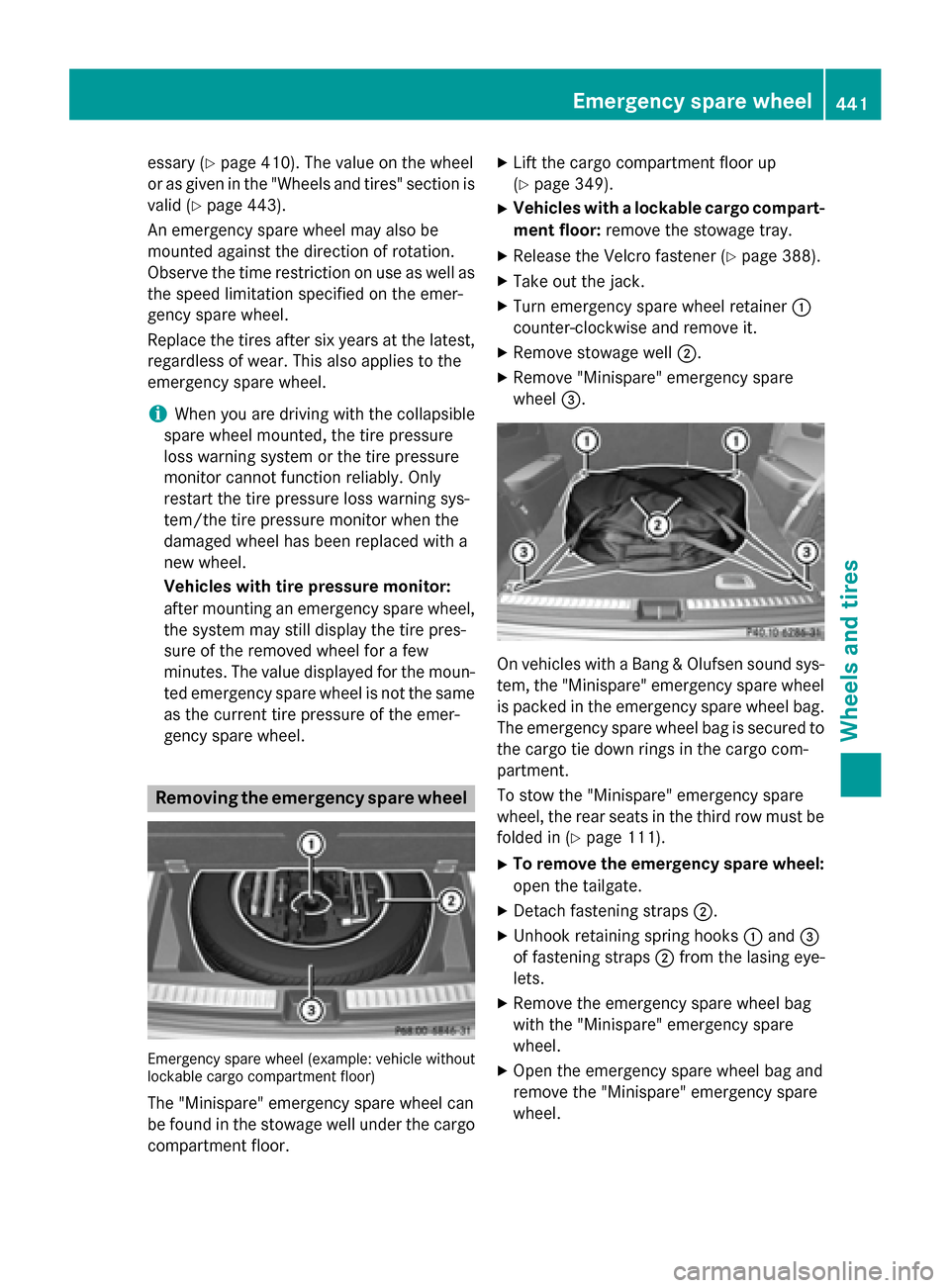
Emergency spare wheel (example: vehicle without
lockable cargo compartment floor)
The "Minispare" emergency spare wheel can
be found in the stowage well under the cargo
compartment floor. X
Lift the cargo compartment floor up
(Y page 349).
X Vehicles with a lockable cargo compart-
ment floor: remove the stowage tray.
X Release the Velcro fastener (Y page 388).
X Take out the jack.
X Turn emergency spare wheel retainer 0043
counter-clockwise and remove it.
X Remove stowage well 0044.
X Remove "Minispare" emergency spare
wheel 0087. On vehicles with a Bang & Olufsen sound sys-
tem, the "Minispare" emergency spare wheel
is packed in the emergency spare wheel bag. The emergency spare wheel bag is secured tothe cargo tie down rings in the cargo com-
partment.
To stow the "Minispare" emergency spare
wheel, the rear seats in the third row must be
folded in (Y page 111).
X To remove the emergency spare wheel:
open the tailgate.
X Detach fastening straps 0044.
X Unhook retaining spring hooks 0043and 0087
of fastening straps 0044from the lasing eye-
lets.
X Remove the emergency spare wheel bag
with the "Minispare" emergency spare
wheel.
X Open the emergency spare wheel bag and
remove the "Minispare" emergency spare
wheel. Emergency spare wheel
441Wheels and tires Z