navigation system MERCEDES-BENZ GL-Class 2015 X166 Owner's Manual
[x] Cancel search | Manufacturer: MERCEDES-BENZ, Model Year: 2015, Model line: GL-Class, Model: MERCEDES-BENZ GL-Class 2015 X166Pages: 462, PDF Size: 9.09 MB
Page 16 of 462
Setting for driving abroad (sym-
metrical) ........................................ 128
Switching on/of f........................... 129
LOW RANGE
Display message ............................ 314
Off-road gear ................................. 261
LOW RANGE off-road gear ................ 261
Lumbar support Adjusting (on the seat) .................. 116
Luxury head restraints ..................... 109M
M+S tires ............................................ 408
Malfunction message see Display messages
Matte finish (cleaning instruc-
tions) .................................................. 380
mbrace Call priority .................................... 361
Display message ............................ 299
Downloading destinations
(COMAND) ..................................... 361
Downloading routes ....................... 364
Emergency call .............................. 358
General notes ................................ 357
Geo fencing ................................... 365
Locating a stolen vehicle ............... 363
MB info call button ........................ 360
Remote vehicle locking .................. 363
Roadside Assistance button .......... 359
Search & Send ............................... 362
Self-test ......................................... 358
Speed alert .................................... 365
System .......................................... 358
Triggering the vehicle alarm ........... 365
Vehicle remote malfunction diag-
nosis .............................................. 364
Vehicle remote unlocking .............. 363
Mechanical key
Function/note s................................ 84
Inserting .......................................... 85
Locking vehicle ................................ 90
Removing ......................................... 84
Unlocking the driver's door .............. 90
Media Interface
see Separate operating instructions
Memory card (audio) ......................... 281 Memory function
............................... 124
Message memory (on-board com-
puter) .................................................. 292
Mirrors see Exterior mirrors
see Rear-view mirror
see Vanity mirror (in the sun visor)
Mobile phone
Menu (on-board computer) ............ 281
Modifying the programming
(SmartKey) ........................................... 83
MOExtended tires .............................. 389
Mounting wheels Lowering the vehicle ...................... 434
Mounting a new whee l................... 433
Preparing the vehicle ..................... 430
Raising the vehicl e......................... 431
Removing a whee l.......................... 433
Securing the vehicle against roll-
ing away ........................................ 430
MP3
Operation ....................................... 281
see separate operating instructions
Multifunction display
Function/note s............................. 276
Permanent display ......................... 285
Multifunction steering wheel
Operating the on-board compute r..2 75
Overview .......................................... 37 N
Navigation Menu (on-board computer) ............ 279
see separate operating instructions
Night View Assist Plus
Activating/deactivating ................. 243
Cleaning ......................................... 383
Problem (malfunction) ................... 245
Notes on breaking-in a new vehi-
cle ....................................................... 166 O
Occupant Classification System
(OCS) Conditions ....................................... 53
Faults ............................................... 57 14
Index
Page 17 of 462
Operation ......................................... 54
System self-test ...............................56
Occupant safety
Automatic measures after an acci-
dent .................................................60
Children in the vehicle .................... .61
Important safety notes .................... 45
Pets in the vehicle ........................... 67
PRE-SAFE ®
(anticipatory occu-
pant protection) ............................... 60
OCS
Conditions ....................................... 53
Faults ............................................... 57
Operation .........................................54
System self-test ............................... 56
Odometer ........................................... 277
Off-road driving Approach/departure angle ............ 457
Checklist after driving off-road ...... 201
Checklist before driving off-road .... 200
Fording depth ................................ 456
General information ....................... 200
Important safety notes .................. 199
Maximum gradient climbing abil-
ity .................................................. 457
Traveling uphill ............................... 202
Off-road programs (vehicles with
the ON&OFFROAD package)
Displays in the COMAND display ... 263
Function/note s............................. 259
Off-road program 1 ........................ 260
Off-road program 2 ........................ 260
Off-road system
4MATIC .......................................... 257
DSR ............................................... 258
LOW RANGE off-road gear ............. 261
Off-road 4ETS .................................. 73
Off-road ABS .................................... 69
Off-road ESP ®
.................................. 75
Off-road programs (vehicles with
the ON&OFFROAD package) .......... 259
Oil
see Engine oil
On and Offroad menu (on-board
computer) .......................................... 289 On-board computer
AMG menu ..................................... 289
Assistance menu ........................... 283
Audio menu ................................... 280
Convenience submenu .................. 287
Displaying a service message ........ 377
Display messages .......................... 292
DISTRONIC PLUS ........................... 213
Factory settings submenu ............. 289
Important safety notes .................. 274
Instrument cluster submenu .......... 285
Lighting submenu .......................... 285
Menu overview .............................. 277
Message memory .......................... 292
Navigation menu ............................ 279
On and Offroad menu .................... 289
Operation ....................................... 275
RACETIMER ................................... 290
Service menu ................................. 284
Settings menu ............................... 285
Standard display ............................ 277
Telephone menu ............................ 281
Trip menu ...................................... 277
Vehicle submenu ........................... 287
Video DVD operation ..................... 281
On-road programs
AUTO program ............................... 255
Function/note s............................. 255
Snow program ............................... 256
SPORT program ............................. 256
Trailer program .............................. 257
Opening and closing the side trim
panels ................................................. 139
Operating safety Declaration of conformity ................ 28
Important safety notes .................... 27
Operating system
see On-board computer
Operator's Manual
Vehicle equipment ........................... 25
Outside temperature display ........... 275
Overhead control panel ...................... 41
Override feature Rear side window s........................... 67 Index
15
Page 19 of 462
Rear seats
Adjusting ....................................... 111
Display messag e............................ 324
Rear view camera
Cleaning instructions ..................... 382
Function/note s............................. 232
Switching on/of f........................... 233
Rear-view mirror
Anti-glare (manual) ........................ 122
Dipping (automatic) ....................... 123
Rear window defroster
Problem (malfunction) ................... 161
Switching on/of f........................... 160
Rear window wiper
Replacing the wiper blad e.............. 142
Switching on/of f........................... 141
Refrigerant (air-conditioning sys-
tem)
Important safety notes .................. 454
Refueling
Fuel gaug e....................................... 35
Important safety notes .................. 185
Refueling process .......................... 186
see Fuel
Remote control
Programming (garage door
opener) .......................................... 366
Replacing bulbs
Important safety notes .................. 137
Overview of bulb types .................. 138
Removing/replacing the cover
(front wheel arch) .......................... 138
Reporting safety defects .................... 29
Reserve (fuel tank) see Fuel
Reserve fuel
Display message ............................ 310
Warning lamp ................................. 335
see Fuel
Residual heat (climate control) ........ 161
Restraint system Display message ............................ 301
Introduction ..................................... 44
Warning lamp ................................. 334
Warning lamp (function) ................... 45 Reversing feature
Panorama sliding sunroof .............. 100
Roller sunblind s............................. 101
Side windows ................................... 95
Sliding sunroof ............................... 100
Tailgate ............................................ 91
Reversing lamps (display mes-
sage) ................................................... 307
Roadside Assistance (breakdown) .... 26
Roller sunblind Panorama roof with power tilt/
sliding panel .................................. 101
Rear side window s......................... 353
Roof carrier ........................................ 350
Roof lining and carpets (cleaning
guidelines) ......................................... 385
Roof load (maximum) ........................ 455
Route (navigation) see Route guidance (navigation)
Route guidance (navigation) ............ 279 S
Safety Children in the vehicle ..................... 61
Child restraint systems .................... 62
Occupant Classification System
(OCS) ............................................... 53
Safety system
see Driving safety systems
Seat belts
Adjusting the driver's and front-
passenger seat belt ......................... 49
Adjusting the height ......................... 48
Cleaning ......................................... 385
Correct usage .................................. 47
Fastening ......................................... 48
Important safety guidelines ............. 46
Introduction ..................................... 46
Releasing ......................................... 49
Switching belt adjustment on/off
(on-board computer) ...................... 288
Warning lamp ................................. 327
Warning lamp (function) ................... 49
Seats
Adjusting (electrically) ................... 108
Adjusting the head restraint .......... 108
Cleaning the cover ......................... 384 Index
17
Page 281 of 462
X
Press the 0076button.
X Press the 0064button to select Yes
Yesand
press the 0076button to confirm.
You can reset the values of the following func-
tions:
R Trip odometer
R "From Start" trip computer
R "From Reset" trip computer
R ECO display
i If you reset the values in the ECO display,
the values in the "From start" trip computer are also reset. If you reset the values in the
"From start" trip computer, the values in
the ECO display are also reset. Navigation system menu
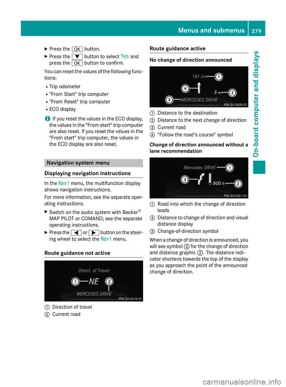
Displaying navigation instructions In the
Navi
Navimenu, the multifunction display
shows navigation instructions.
For more information, see the separate oper-
ating instructions.
X Switch on the audio system with Becker ®
MAP PILOT or COMAND; see the separate
operating instructions.
X Press the 0059or0065 button on the steer-
ing wheel to select the Navi Navimenu.
Route guidance not active 0043
Direction of travel
0044 Current road Route guidance active No change of direction announced
0043
Distance to the destination
0044 Distance to the next change of direction
0087 Current road
0085 "Follow the road's course" symbol
Change of direction announced without a lane recommendation 0043
Road into which the change of direction
leads
0044 Distance to change of direction and visual
distance display
0087 Change-of-direction symbol
When a change of direction is announced, you
will see symbol 0087for the change of direction
and distance graphic 0044. The distance indi-
cator shortens towards the top of the display
as you approach the point of the announced
change of direction. Menus and submenus
279On-board computer and displays Z
Page 331 of 462
Problem
Possible causes/consequences and
0050
0050Solutions 0025
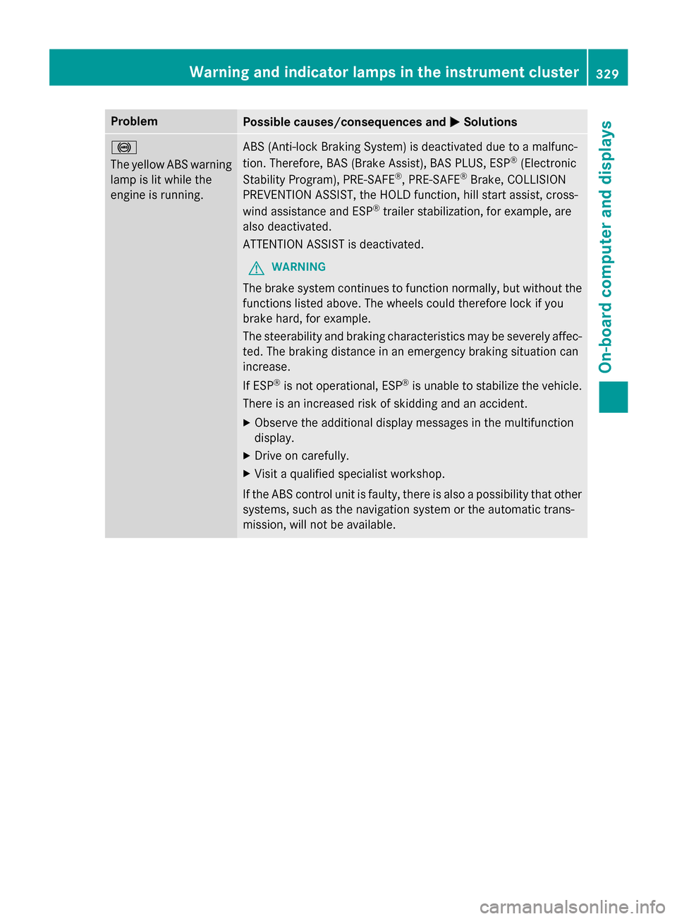
The yellow ABS warning
lamp is lit while the
engine is running. ABS (Anti-lock Braking System) is deactivated due to a malfunc-
tion. Therefore, BAS (Brake Assist), BAS PLUS, ESP ®
(Electronic
Stability Program), PRE‑ SAFE®
, PRE‑SAFE ®
Brake, COLLISION
PREVENTION ASSIST, the HOLD function, hill start assist, cross-
wind assistance and ESP ®
trailer stabilization, for example, are
also deactivated.
ATTENTION ASSIST is deactivated.
G WARNING
The brake system continues to function normally, but without the functions listed above. The wheels could therefore lock if you
brake hard, for example.
The steerability and braking characteristics may be severely affec-ted. The braking distance in an emergency braking situation can
increase.
If ESP ®
is not operational, ESP ®
is unable to stabilize the vehicle.
There is an increased risk of skidding and an accident.
X Observe the additional display messages in the multifunction
display.
X Drive on carefully.
X Visit a qualified specialist workshop.
If the ABS control unit is faulty, there is also a possibility that other
systems, such as the navigation system or the automatic trans-
mission, will not be available. Warning and indicator lamps in the instrument cluster
329On-board computer and displays Z
Page 362 of 462
X
Press Roadside Assistance button 0043.
This initiates a call to the Mercedes-Benz
Customer Assistance Center.
The indicator lamp in Roadside Assistance
button 0043flashes while the call is active.
The multifunction display shows the Con‐ Con‐
necting Call
necting Call message. The audio output
is muted.
If a connection can be made, the Call Con‐
Call Con‐
nected
nected message appears in the multifunction
display.
If a mobile phone network and GPS reception are available, the system transfers data to the
Mercedes-Benz Customer Assistance Center, for example:
R current location of the vehicle
R vehicle identification number
i The audio system or COMAND display
indicates that a call is active. During the
call, you can change to the navigation menu
by pressing the NAVI button on COMAND,
for example.
Voice output is not available.
A voice connection is established between
the Mercedes-Benz Customer Assistance
Center and the vehicle occupants.
From the vehicle remote malfunction diagno- sis, the Mercedes-Benz Customer Assistance
Center can ascertain the nature of the prob-
lem (Y page 364).
The Mercedes-Benz Customer Assistance
Center either sends a qualified Mercedes-
Benz technician or makes arrangements for
your vehicle to be transported to the nearest
authorized Mercedes-Benz Center.
You may be charged for services such as
repair work and/or towing.
Further details are available in your mbrace
manual. i
The system has not been able to initiate a
Roadside Assistance call, if:
R the indicator lamp for Roadside Assis-
tance call button 0043is flashing continu-
ously.
R no voice connection to the Mercedes-
Benz Customer Assistance Center was
established.
This can occur if the relevant mobile phone network is not available, for example.
The Call Failed
Call Failed message appears in the
multifunction display.
X To end a call: press the0076button on the
multifunction steering wheel.
or
X Press the corresponding button for ending
a phone call on the audio system or on
COMAND.
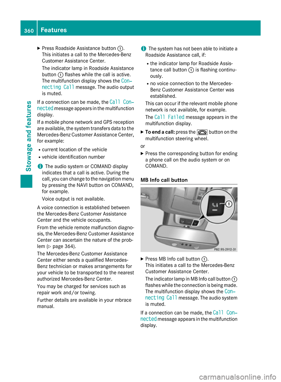
MB Info call button X
Press MB Info call button 0043.
This initiates a call to the Mercedes-Benz
Customer Assistance Center.
The indicator lamp in MB Info call button 0043
flashes while the connection is being made.
The multifunction display shows the Con‐ Con‐
necting
necting Call
Callmessage. The audio system
is muted.
If a connection can be made, the Call Con‐
Call Con‐
nected
nected message appears in the multifunction
display. 360
FeaturesStowage and features
Page 363 of 462
If a mobile phone network and GPS reception
are available, the system transfers data to the
Mercedes-Benz Customer Assistance Center, for example:
R current location of the vehicle
R vehicle identification number
i The audio system or COMAND display
indicates that a call is active. During the
call, you can change to the navigation menu
by pressing the NAVI button on COMAND,
for example.
Voice output is not available.
A voice connection is established between
the Mercedes-Benz Customer Assistance
Center and the vehicle occupants.
You receive information about operating your vehicle, about the nearest authorized
Mercedes-Benz Center and about other prod-
ucts and services from Mercedes-Benz.
USA only: you can find further information on
the mbrace system under "Owners Online" at
http://www.mbusa.com.
i The system has not been able to initiate
an MB Info call, if:
R the indicator lamp in MB Info call but-
ton 0043is flashing continuously.
R no voice connection to the Mercedes-
Benz Customer Assistance Center was
established.
This can occur if the relevant mobile phone network is not available, for example.
The Call Failed
Call Failed message appears in the
multifunction display.
X To end a call: press the0076button on the
multifunction steering wheel.
or
X Press the corresponding button for ending
a phone call on the audio system or on
COMAND. Call priority When service calls are active, e.g. Roadside
Assistance or MB Info calls, an emergency
call can still be initiated. In this case, an emer-
gency call will take priority and override all
other active calls.
The indicator lamp of the respective button
flashes until the call is ended.
An emergency call can only be terminated by the Mercedes-Benz Customer Assistance
Center.
All other calls can be ended by pressing:
R the 0076 button on the multifunction steer-
ing wheel
R the corresponding button on the audio sys-
tem or on COMAND for ending a telephone
call
i When a call is initiated, the audio system
is muted. The mobile phone is no longer
connected to COMAND. However, if you
want to use your mobile phone, do so only
when the vehicle is stationary and in a safe
location.
Downloading destinations in COMAND Downloading destinations
Downloading destinations gives you access
to a database with over 15 million points of
interest (POIs). These can be downloaded on
the navigation system in your vehicle. If you
know the destination, the address can be
downloaded. Alternatively, you can obtain the
location of Points of Interest (POIs)/impor-
tant destinations in the vicinity.
Furthermore, you can download routes with
up to 20 way points.
You are prompted to confirm route guidance
to the address entered.
The system calculates the route and subse-
quently starts the route guidance with the
address entered.
i If you select
No No, the address can be saved
in the address book. Features
361Stowage and features Z
Page 364 of 462
i
The destination download function is
available if the relevant mobile phone net-
work is available and data transfer is pos-
sible.
i The destination download function can
only be used if the vehicle is equipped with
a navigation system.
Route Assistance
This service is part of the mbrace PLUS Pack- age and cannot be purchased separately.
i You can also use the Route Assistance
function if your vehicle is not equipped with
a navigation system.
Within the framework of this service, you
receive a professional and reliable form of
navigation support without having to leave
your vehicle.
The customer service representative finds a
suitable route depending on your vehicle's
current position and the desired destination.
You will then be guided live through the cur-
rent route section.
Search & Send General notes
i To use "Search & Send", your vehicle
must be equipped with mbrace and a navi-
gation system. Additionally, an mbrace ser-
vice subscription must be completed.
"Search & Send" is a destination entry ser-
vice. A destination address which is found on Google Maps ®
can be transferred via mbrace
directly to your vehicle's navigation system.
Specifying and sending the destination
address
X Go to the website http://
www.maps.google.com and enter a desti-
nation address into the entry field.
X To send the destination address to the
e-mail address of your mbrace account:
click on the corresponding button on the
website. i
Example:
If you select 'Send to vehicle' and then
'Mercedes-Benz', the destination address
will be sent to your vehicle.
X When the "Send" dialog window appears:
Enter the e-mail address you specified
when setting up your mbrace account into
the corresponding field.
X Click "Send".
i Information on specific commands such
as "Address entry" or "Send" can be found
on the website.
Calling up destination addresses
X Switch on the ignition.
The destination address is loaded into the
vehicle's navigation system.
A display message appears, asking
whether navigation should be started.
X Select Yes Yesby turning 00790052007Aor sliding 009500520096
the COMAND controller and press 0098to
confirm.
The system calculates the route and sub-
sequently starts the route guidance with
the address entered.
i If you select
No No, the address can be saved
in the address book.
i If you have sent more than one destina-
tion address, each individual destination
must be confirmed separately.
i Destination addresses are loaded in the
same order as the order in which they were
sent.
If you own multiple Mercedes-Benz vehi-
cles with mbrace and activated mbrace
accounts:
If multiple vehicles are registered under the
same e-mail address, the destination will
be sent to all the vehicles. 362
FeaturesStowage and features
Page 366 of 462
i
If the anti-theft alarm system is activated
for longer than 30 seconds, the Mercedes-
Benz Customer Assistance Center is auto-
matically notified.
Vehicle remote malfunction diagnosis With the vehicle remote malfunction diagno-
sis (Vehicle Health Check), the Customer
Assistance center can provide improved sup- port for problems with your vehicle. During anexisting call, vehicle data is transferred to the
Customer Assistance center. The customer
service representative can use the received
data to decide what kind of assistance is
required. You are then, for example, guided to the nearest authorized Mercedes-Benz Cen-
ter or a recovery vehicle is called.
If vehicle data needs to be transferred during
an MB Info call or a Roadside Assistance call, this is initiated by the Customer Assistance
center. You will see the Roadside Assis‐
Roadside Assis‐
tance Connected
tance Connected message in the COMAND
display. If the vehicle remote malfunction
diagnosis can be started, the Request for Request for
vehicle diagnosis received. Start
vehicle diagnosis received. Start
vehicle diagnosis?
vehicle diagnosis? message appears in
the display.
X Confirm the message with Yes
Yes.
X When the Vehicle Diagnosis Please
Vehicle Diagnosis Please
start ignition
start ignition message appears, turn
the SmartKey to position 2in the ignition
lock (Y page 167).
X When the Please
Pleasefollow
followthe
theinstruc‐
instruc‐
tions received by phone and move
tions received by phone and move
your vehicle to a safe position. your vehicle to a safe position.
message appears, follow the customer ser-
vice representative's instructions.
The message in the display disappears.
If you select Cancel
Cancel, the vehicle remote
malfunction diagnosis is canceled com-
pletely.
The vehicle operating state check begins.
You will see the Vehicle diagnosis Vehicle diagnosis
activated.
activated. message. When the diagnosis is completed, the
Send Send
vehicle diagnostics data//(Voice vehicle diagnostics data//(Voice
connection may be//interrupted dur‐ connection may be//interrupted dur‐
ing ing data
data transfer)
transfer) message appears. The
vehicle data can now be sent to the Customer Assistance center.
X Press OK
OK to confirm the message.
The voice connection with the Customer
Assistance center is terminated.
You will see the Vehicle Diagnosis: Vehicle Diagnosis:
Transferring data... Transferring data... message.
The vehicle data is sent to the Customer
Assistance center.
Depending on what the customer service rep-
resentative agreed with you, the voice con-
nection is re-established after the transfer is
complete. If necessary, you will be contacted at a later time by another means, e.g. by e-
mail or phone.
Further functions of the vehicle remote mal-
function diagnosis include, for example:
R transfer of service data to the Customer
Assistance center. If a service is overdue,
the COMAND display shows a message
about various special offers at your work-
shop.
R monthly status information e-mail on oil
level, air pressure, maintenance, brakes,
etc. If applicable, you will receive informa-
tion on special offers in the e-mail.
USA only: this information can also be
called up under "Owners Online" at http://
www.mbusa.com.
Information on the data stored in the vehicle
(Y page 30).
Information on Roadside Assistance
(Y page 26).
Downloading routes Downloading routes allows you to transfer
and save predefined routes in the navigation
system. To do this, an SD memory card must
be inserted into the COMAND system. If no
SD memory card is inserted, you must insert 364
FeaturesStowage and features
Page 367 of 462
the card into the card slot on the COMAND
system before saving.
A route can be prepared and sent either by a customer service representative or via the
mbrace portal on the Internet.
Each route can include up to 20 way points.
Once a route has been received by the navi-
gation system, you will see the
name> has hasbeen
been saved
saved to
tomemory
memory card.
card.
Do
Do you
you want
want to
tostart
start route
routeguidance?
guidance?
message in the COMAND display. The route is
saved to the SD memory card.
X To start route guidance: selectYes
Yes.
An overview of the route is shown in the
display.
i If you select
No No, the saved route can be
called up later via the navigation menu.
X Select Start
Start.
Route guidance is started.
i Downloaded and saved data can be called
up again in COMAND.
You can find further information in the sep-
arate COMAND Operating Instructions.
Speed alert You can define the upper speed limit, which
must not be exceeded by the vehicle.
If this selected speed is exceeded by the vehi-
cle, a message will be sent to the Customer
Assistance Center. The Customer Assistance Center then forwards this information to you.
You can select the way in which you receive
this information beforehand. Possible options
include text message, e-mail or an automated call.
The data you receive contains the following
information:
R the location where the speed limit was
exceeded
R the time at which the speed limit was
exceeded
R the selected speed limit which was excee-
ded Geo fencing Geo fencing allows you to select areas which
the vehicle should not enter or leave. You will be informed if the vehicle crosses the boun-
daries of the selected areas. You can select
the way in which you receive this information
beforehand. Possible options include text
message, e-mail or an automated call.
The area can be determined as either a circle
or a polygon with a maximum of ten corners. You can specify up to ten areas simultane-
ously. Different settings are possible for each
area.
USA only: these settings can be called up
under "Owners Online" at http://
www.mbusa.com.
Alternatively, you can trigger an MB Info call
and inform the customer service representa-
tive that you wish to activate geo fencing.
Currently inactive areas can be activated by
text message.
Triggering the vehicle alarm With this function, you can trigger the vehi-
cle's panic alarm via text message. An alarm
sounds and the exterior lighting flashes.
Depending on the setting, the panic alarm
lasts five or ten seconds. Afterwards, the
alarm switches off.
Garage door opener
General notes The HomeLink
®
garage door opener integra-
ted in the rear-view mirror allows you to oper-
ate up to three different door and gate sys-
tems.
Use the integrated garage door opener only
on garage doors that:
R have safety stop and reverse features and
R meet current U.S. federal safety standards
Once programed, the integrated garage door opener in the rear-view mirror will assume the
function of the garage door system's remote Features
365Stowage an d features Z