width MERCEDES-BENZ GL SUV 2012 Owners Manual
[x] Cancel search | Manufacturer: MERCEDES-BENZ, Model Year: 2012, Model line: GL SUV, Model: MERCEDES-BENZ GL SUV 2012Pages: 441, PDF Size: 10.66 MB
Page 210 of 441
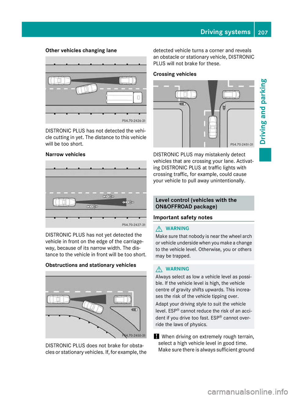
Other vehicles changing lane
DI
ST RONIC PLUS has not detected the vehi-
cle cutting in yet. The distance to this vehicle
will be too short.
Narrow vehicles DISTRONIC PLUS has not yet detected the
vehicle in fron tonthe edge of the carriage-
way, because of its narrow width. The dis-
tance to the vehicle in front will be too short.
Obstruction sand sta tionary vehicles DISTRONIC PLUS does not brake for obsta-
cles or stationary vehicles. If, for example, the detected vehicle turns
acorner and reveals
an obstacle or stationar yvehicle, DI STRONIC
PLUS will not brake for these.
Crossin gvehicles DISTRONIC PLUS may mistakenly detect
vehicles that are crossing your lane. Activat-
ing DISTRONIC PLUS at traffic lights with
crossing traffic, for example, could cause
your vehicle to pull away unintentionally.
Level control (vehicles with the
ON&OFFROAD package)
Important safety notes G
WARNING
Make sure that nobody is near the wheel arch
or vehicle underside when you make achange
to the vehicle level. Otherwise, you or others
ma ybet rapped. G
WARNING
Always select as lo wavehicle level as possi-
ble. If the vehicle level is high, the vehicle
centre of gravity shifts upwards. This increa-
ses the risk of the vehicle tippin gover.
Adapt you rdriving style to suit th evehicle
level. ESP ®
cannot reduc ethe risk of an acci-
dent if you drive too fast. ESP ®
cannot over-
rid ethe laws of physics.
! When driving on extremel yrough terrain,
select ahigh vehicle level in good time.
Make sure there is always sufficient ground Drivin
gsystems
207Drivingand pa rking Z
Page 228 of 441
To deactivate:
the reversing camera is deac-
tivated if you:
R sh iftt he transmission to position P
R drive for wards 10 m
R shift th etransmission from Rto another
positio n(after 15 seconds)
R driv eforwards at aspee dofover
10 km/h
Display sintheCOMAN Ddisplay G
WARNING
Usin gthe reversing camera ca nbedangerous
if you are colour-blind or if your abilit ytodis-
tinguish colours is impaired.
Only use th ereversing camera if you can see
and distinguish between all th ecoloured
guide lines that are displayed by the reversing
camera in the COMAN Ddisplay. G
WARNING
Please note that object snot at groun dlevel
may appear to be further away than they
actually are. These include:
R the bumper of avehicle that is parked
behind your vehicle
R at railer drawbar
R theb all coupling of atrailer tow hitch
R thet ail-end of alorry
R slanted posts
The lines are only guides, not accurate meas-
urements of the distance to an obstacle.
Therefore, you should never pass the red line
when approachin ganobstacle. You could oth-
erwise cause an accident and injur eyourself
and others. :
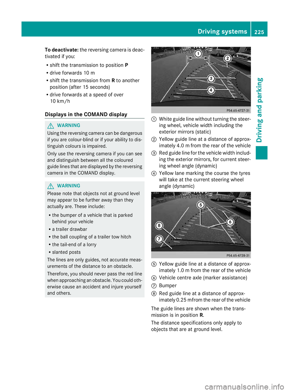
White guide line without turnin gthe steer-
ing wheel, vehicle widt hincluding the
exterior mirrors (static)
; Yellow guid eline at adistance of approx-
imately 4.0 mfrom th erear of the vehic le
= Red guide line for the vehicl ewidth includ-
ing the exterior mirrors, for current steer-
ing whee langle (dynamic)
? Yellow lane marking the course the tyres
willtake at the current steering wheel
angle (dynamic) A
Yellow guide line at adistance of approx-
imately 1.0 mfrom th erear of the vehic le
B Veh icle centr eaxle (marker ass istance)
C Bumper
D Red guide line at adistance of approx-
imately 0.2 5mfrom th erear of the vehic le
Th eg uide lines are sho wn whenthe trans-
mission is in position R.
The distance specifications only apply to
object sthat ar eatground level. Dri
ving systems
225Driving and pa rking Z
Page 229 of 441
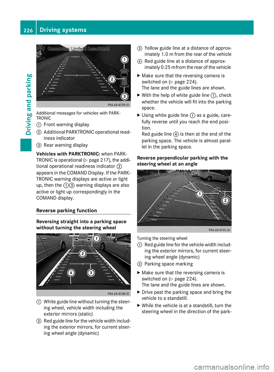
Additiona
lmessages for vehicles with PARK-
TRONIC
: Fron twarning display
; Additiona lPARKTRONIC operationa lread-
iness indicator
= Rear warning display
Veh icleswithP ARKTRONIC: when PARK-
TRONIC is operationa l(Y page 217), the addi-
tional operat iona lreadiness indicator ;
appears in the COMAN DDisplay. If the PARK-
TRONIC warnin gdisplays are active or light
up ,then the :=warnin gdisplays are also
active or light up correspondingl yinthe
COMAND display.
Reverse parkin gfunction Reversin
gstraight into aparkin gspace
withou tturning the ste eringwheel :
White gu idel ine without turning the steer-
ing wheel, vehicle width including the
exterior mirrors (static)
; Red guide line for the vehicle width includ-
ing the exterior mirrors, for current steer-
ing wheel angle (dynamic) =
Yellow guide line at adistance of approx-
imately 1.0 mfrom th erear of the vehic le
? Red guide line at adistance of approx-
imately 0.2 5mfrom th erear of the vehic le
X Ma ke sure that the reversing camera is
switched on (Y page224).
Th elane and the guide lines are sho wn.
X Wi th the hel pofwhite guide line :,check
whether the vehicle will fit into the parking
space.
X Using white guide line :asag uide, care-
fully reverse until you reach the end posi-
tion.
Red guide line ?is then at the end of the
parking space. The vehicle is almost paral-
lel in the parking space.
Reverse perpendicular parking with the
steering wheel at an angle Turning the steering wheel
:
Red guide line for the vehicle width includ-
ing the exterior mirrors, for current steer-
ing wheel angle (dynamic)
; Parking space marking
X Make sure that the reversing camera is
switched on (Y page 224).
The lane and the guide lines are shown.
X Drive past the parking space and bring the
vehicle to astandstill.
X While the vehicle is at astandstill, turn the
steering whee lint he direction of the park- 226
Driving systemsDriving and pa
rking
Page 230 of 441
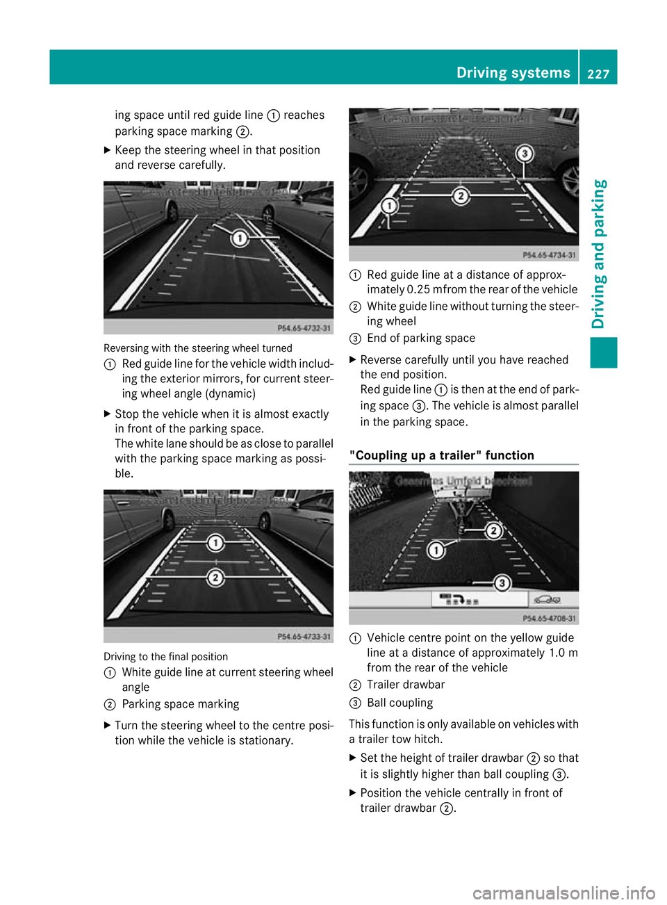
ing space until red guide line
:reaches
parking space mar king ;.
X Keep the steering wheel in that position
and reverse carefully. Reversing with the steerin
gwheel turned
: Red guide line for the vehicle width includ-
ing the exterior mir rors, for current steer-
ing whee langle (dynamic)
X Stop the vehicle whe nitisalmost exactly
in fron tofthe par king space.
The whit elane should be as close to parallel
with the parking space marking as possi-
ble. Drivin
gtothe final position
: Whit eguide line at current steerin gwheel
angle
; Parking space marking
X Turn the steering wheel to the centr eposi-
tion while the vehicle is stationary. :
Red guide line at adistanc eofapprox-
imately 0.2 5mfrom th erear of the vehicle
; White guide line without turning the steer-
ing wheel
= End of park ings pace
X Reverse carefully unti lyou have reached
the end position.
Red guide line :is then at the end of park-
ing space =.The vehicle is almost parallel
in the parkin gspace.
"Coupling up atrailer" function :
Vehicle centre point on the yellow guide
line at adistance of approximately 1.0 m
from the rear of the vehicle
; Trailer drawbar
= Ball coupling
This func tion is only available on vehicles with
at railer to whitch.
X Set the height of trailer drawbar ;so that
it is slightly higher than ball coupling =.
X Position the vehicle centrally in front of
trailer drawbar ;. Drivin
gsystems
227Drivingand pa rking Z
Page 233 of 441
Activating th
e360° camera using
revers egear You can show images from th
e360°c amera
automatically by engagin grevers egear.
X Mak esuret hat the key is in position 2in
th ei gnition lock.
X Mak esuret hat the Activation by R gear setting is ac
tive in COMAND Online,
se et he separa teCOMAND Onlin eoperat-
ing instructions.
X To sho wthe360° camera image: engage
revers egear.
The COMAND display show sthe ar ea
behind th evehicl einS plitS creen:
R vehicl ewithg uide lines
R top vie wofthe vehicle
Selec ting th esplit-screen and full
screen displays X
To switch between split-scree nviews:
switc htot he line with the vehi cles ymbols
by sliding ZVthe COMAND controller.
X Turn cVd the COMAND controlle rand
select one of the vehicle symbols.
X To switch to full scree nmode: select
Full scre en by tur
ning cVd the
COMAN Dcontroller and press Wto con-
firm.
Display sinthe COMAND display Important safety notes
!
Objec tsnot at ground level may appear to
be further away than they actually are, e.g.:
R the bumpe rofaparked vehicle
R the drawbar of atrailer
R theb all coupling of atrailer to whitch
R the rear section of an HGV
R as lanted post
Use the guidelines only for orientation.
Approach object snofurther than the bot-
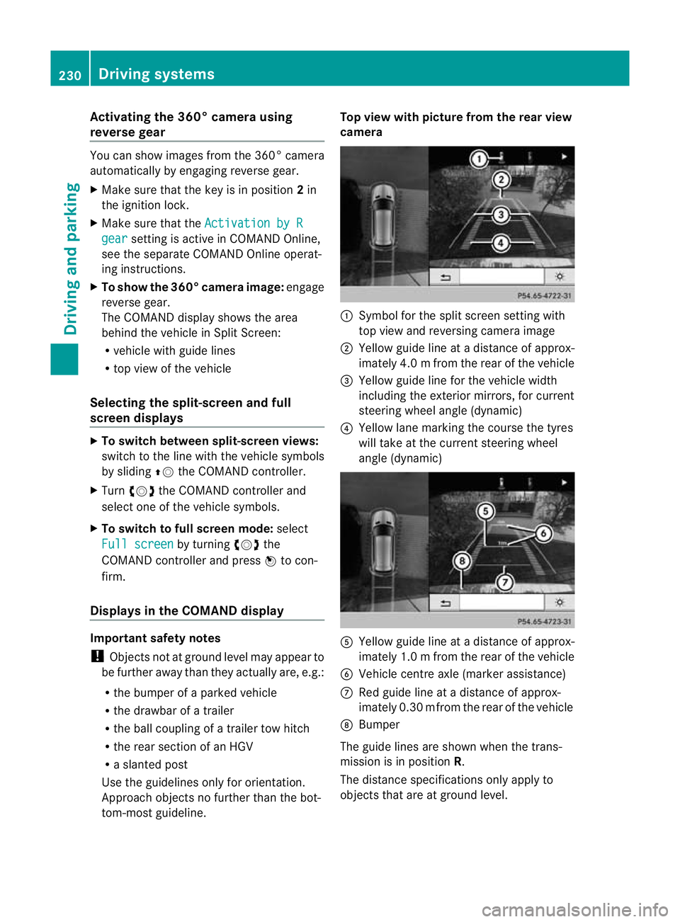
tom-most guidel ine. Top vie
wwith pictu re from the rear view
camera :
Symbol for the split screen settin gwith
top view and reversing camera image
; Yellow guide line at adistance of approx-
imately 4.0 mfrom th erear of the vehic le
= Yellow guide line for the vehicle width
including the exterior mirrors, for current
steering whee langle (dynamic)
? Yellow lane marking the course the tyres
wil ltake at the current steering wheel
angle (dynamic) A
Yellow guide line at adistance of approx-
imately 1.0 mfrom th erear of the vehic le
B Veh icle centr eaxle (marker ass istance)
C Red guide line at adistance of approx-
imately 0.3 0mfrom th erear of the vehic le
D Bumper
Th eg uide lines are sho wn whenthe trans-
mission is in position R.
The distance specifications only apply to
object sthat ar eatground level. 230
Dri
ving systemsDriving and pa rking
Page 234 of 441
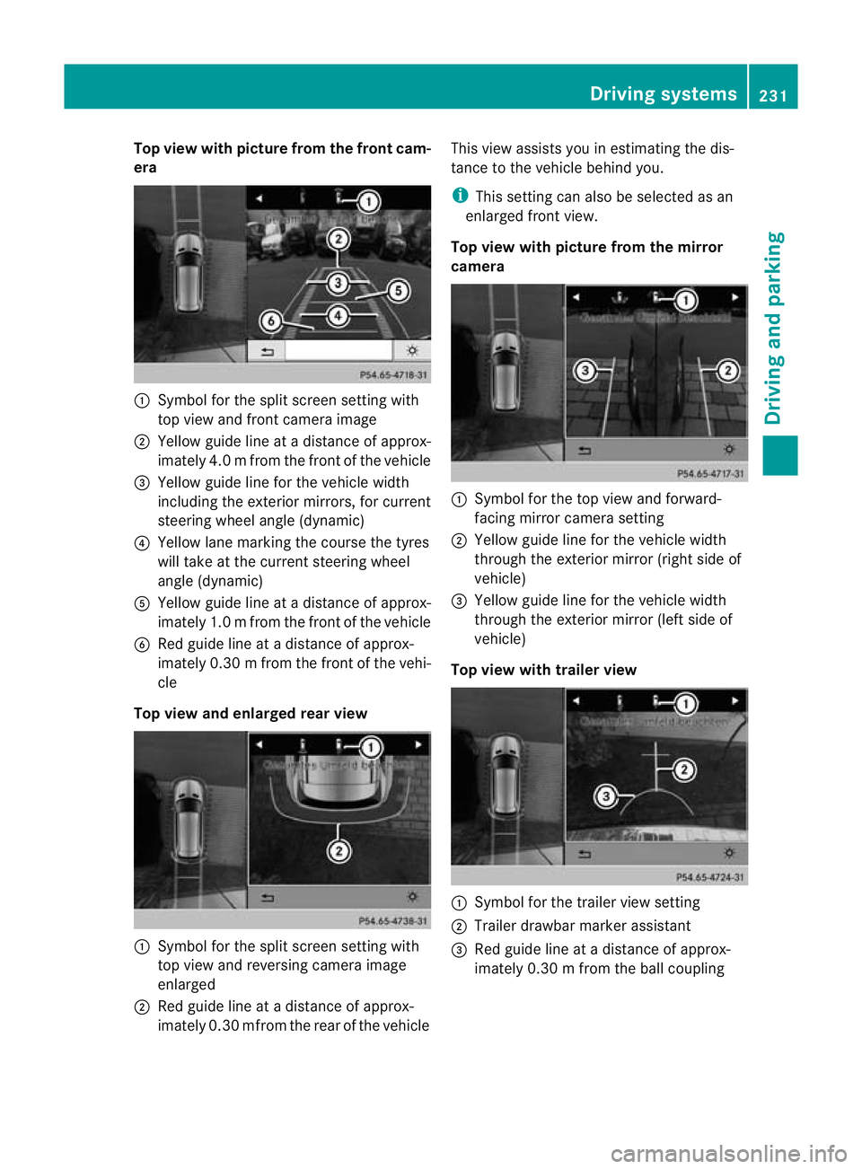
Top view with picture from the fron
tcam-
era :
Symbo lfor the split scr eens etting with
top view and front camera image
; Yellow guid elineatad istance of approx-
imatel y4.0mf rom th efront of th evehicle
= Yellow guid elinef or the vehicle width
inc ludi ng the exterio rmirrors ,for current
steering whee langle (dynamic)
? Yellow lane marking the course the tyres
will take at the current steering wheel
angle (dynamic)
A Yellow guid elineatad istance of approx-
imatel y1.0mf rom th efront of th evehicle
B Redg uide line at adistan ce of approx-
imatel y0.30 mfrom th efront of th evehi-
cle
Top view and enlarged rea rview :
Symbol for the spli tscree nsetting with
top view and reversing camera image
enlarged
; Red guide line at adistanc eofapprox-
imately 0.3 0mfrom th erear of the vehicle This view assists you in estim
ating the dis-
tance to the vehicle behind you.
i This setting can als obeselected as an
enlarged front view.
Top view with picture from th emirror
camera :
Symbo lfor the top view and forward-
facing mirror camera setting
; Yellow guide line for the vehicle width
through the exterior mirror (ri ghts ide of
vehicle)
= Yellow guide line for the vehicle width
through the exterior mirror (left side of
vehicle)
Top vie wwitht railer view :
Symbo lfor the trailer view setting
; Trailer drawbar marker assistant
= Red guide line at adistance of approx-
imately 0.3 0mfrom th eballc oupling Drivin
gsystems
231Drivingand parking Z
Page 242 of 441
change lane, yo
uwilla lsor eceive an optical
and audible collisio nwarning. For monitoring,
Active Blin dSpot Assist uses sensors in the
rear bumper.
For Blin dSpot Assist to assist you when driv-
ing, the rada rsensor system must be activa-
ted (Y page 283) and operational.
The rada rsensor system is switched off auto-
maticall yinthe vicinit yofradio telescope
facilities (Y page 433).
Monitoring range of the sensors G
WARNING
Blind Spot Assist monitors certain areas in the
immediate vicinit yofyour vehicle. Vehicles
that approach and driv epast at high speeds
are not detected. There is no display and no
warning.
If the lanes are very wide, it may not be pos-
sible to monitor the complete width of the
neighbouring lane. For this reason, vehicles in
the next lane may not be detected, especially
if they are driving in astaggered formation in
different lanes .This ma ybethe case if vehi-
cles ar edriving at th eedge of their lane that
is furthest away from your vehicle.
Alway spay attention to traffic conditions and
your surroundings. Otherwise ,you may fai lto
recognis edangers in time, cause an accident
and injure yourself and others. Blind Spot Assis
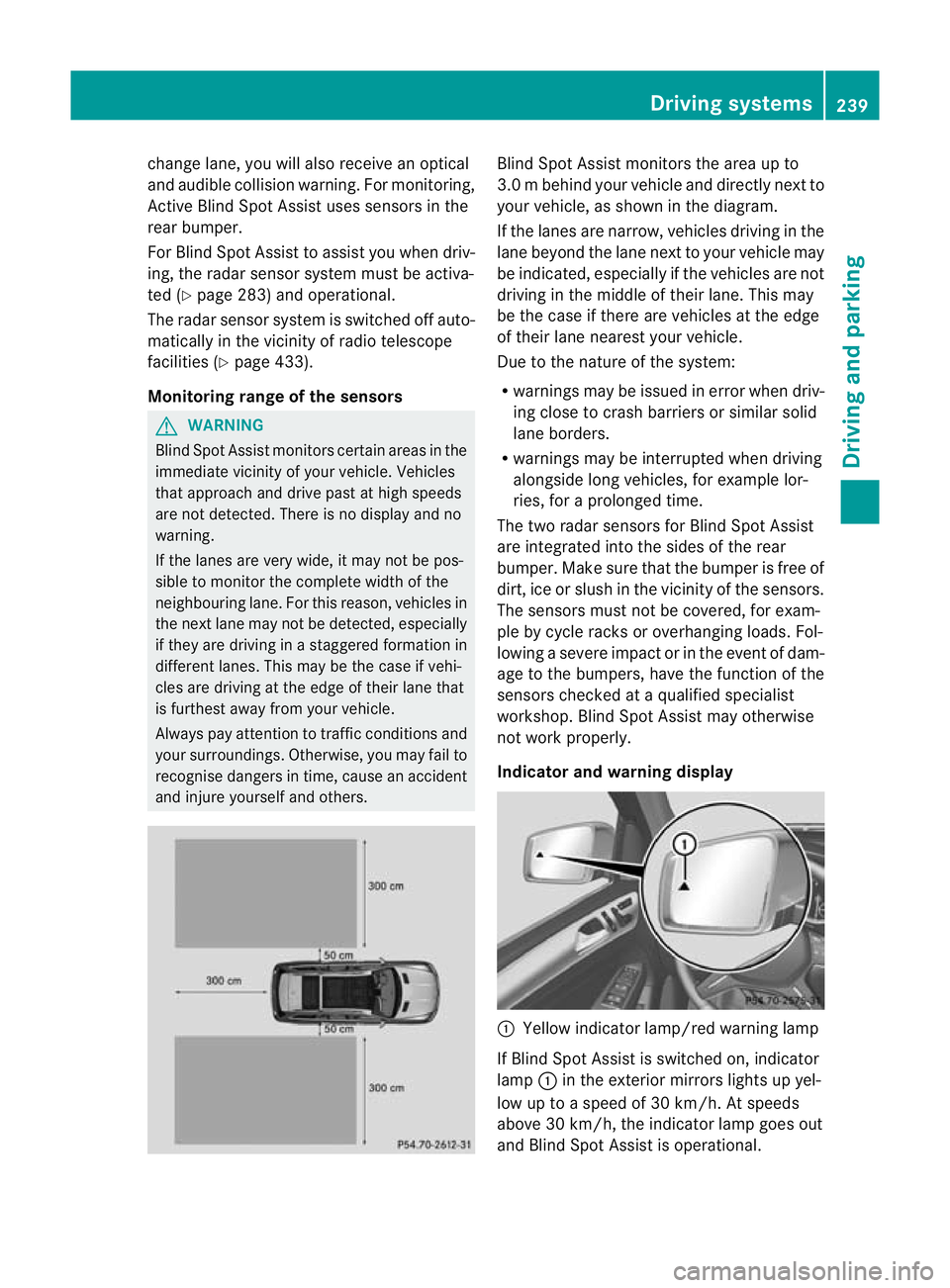
tmonitors the area up to
3. 0mb ehind your vehicle and direc tlyn extto
your vehicle, as shown in the diagram.
If the lanes are narrow, vehicles drivin gint he
lan ebeyond th elan en ext to your vehicle may
be indicated, especially if th evehicles are not
drivin gint he midd le of their lane. This may
be th ecase if there are vehicles at th eedge
of their lan eneares tyour vehicle.
Due to th enature of th esystem:
R warnings may be issued in error when driv-
ing close to crash barriers or similar solid
lane borders.
R warnings may be interrupted when driving
alongside long vehicles, for example lor-
ries, for aprolonged time.
Th et wo radar sensors for Blin dSpot Assist
are integrated int othe sides of the rear
bumper .Make sure that the bumper is free of
dirt, ice or slush in the vicinity of the sensors.
The sensor smust not be covered, for exam-
ple by cycle racks or overhanging loads .Fol-
lowin gasevereimpact or in th eevent of dam-
ag etot he bumpers, hav ethe function of the
sensor schecked at aqualified special ist
workshop. Blind Spot Assist may otherwise
not work properly.
Indicator and warning display :
Yello windicato rlamp/red warning lamp
If Blind Spot Assis tiss witched on, indicator
lamp :in the exterior mirrors lights up yel-
low up to aspeed of 30 km/h. At speeds
above 30 km/h, the indicator lamp goes out
and Blin dSpot Assist is operational. Driving systems
239Driving and parking Z
Page 245 of 441
marking
,the system recognises certai ncon-
ditions and warns you accordingly.
The warning vibration occur searlier if:
R you approach the outer lane markin gona
bend.
R the road has ver ywidel anes ,e.g. am otor-
way.
R the system recognises solid lane markings.
The warning vibration occur slater if:
R the road has narrow lanes.
R you cut the corner on abend. Active Driving Assistance package
General notes The Active Drivin
gAssistanc epackag econ-
sists of DISTRONIC PLU S(Ypa ge198), Active
Blind Spo tAssist (Y page 242) and Active
Lane Keeping Assist (Y page 246).
Active Blind Spot Assist Importan
tsafety notes G
WARNING
Active Blind Spo tAssist is only an aid and may
detect vehicles/obstacles incorrectly or not
at all.
The system ma ybeimpaired or may not func-
tio nif:
R there is po orvisibility ,e.g. due to snow,
rain, fog or spray.
R the rear and/or front sensors are dirty.
Active Blind Spot Assist may not detect nar-
row vehi cles, such as motorcycles or bicycles,
or only detect the mtoo late. It can notd etect
vehicles which are overtaken at asmall dis-
tance and then enter th eblind spot area.
Active Blind Spot Assist cannot detect road
and traffic conditions. It is not asubstitute for
attentive driving. You are responsible for the
vehicle's speed, braking in good time, and
steering correctly. Always adapt your driving
style to suit the prevailing road and weather conditions. Always pay attention to traffic
conditions and your surroundings. Otherwise,
you may fail to recognise dangers in time,
cause an accident and injure yourself and oth-
ers.
The radar sensor syste misautomatically
deactivated near radio telescope facilities
(Y page 433).
For Active Blind Spot Assis ttoassist you
when driving, the radar sensor syste mmust
be activated (Y page 283)and operational.
General notes
Active Blind Spot Assist use saradar sensor
system to monitor the area to the sides of
your vehicle which are behind the driver. A
warning display in the exterior mirrors draws
your attention to vehicles detected in the
monitored area. If you then switch on the cor-
responding turn signal to change lane, you
will also receive an optical and audible warn-
ing. If arisk of lateral collision is detected,
corrective brakin gmay help you avoid acol-
lision. To suppor tthe course- correcting brake
application ,Active Blind Spo tAssist uses the
forward-facin gradar senso rsystem. The free
space in the direction of travel is then evalu-
ated.
Active Blind Spot Assist supports you from a
speed of approximatel y30km/h.
Monitorin grange G
WARNING
Active Blin dSpot Assist monitors cer tain
areas in the immediate vicinit yofyour vehicle.
Vehicles that approach and driv epast at high
speeds are not detected. No visual nor audi-
ble warnings are emitted and the system does
not brake the vehicle to correc tyour course.
If the lanes are ver ywide, it may not be pos-
sible to monitor the complete width of the
neighbouring lane. For this reason, vehicles in
the next lane may not be detected, especially
if they are drivin ginastaggered formation.
Thi sm ay be the case if vehicles are driving at 242
Driving systemsDrivin
gand pa rking
Page 400 of 441
other obstacles. If it is necessary to drive over
kerbs, speed humps or similar elevations, try
to do so slowly and at an obtuse angle .Oth-
erwise ,the tyres, particularly the sidewalls,
ma ybed amaged. Regular checking of wheels and tyres
G
WARNING
Damaged tyres can cause tyre inflation pres-
sure loss .Asaresult,you coul dlose control
of your vehicle. There is arisk of accident.
Check the tyres regularly for signs of damage
and replace any damaged tyres immediately.
Regularly check the wheels and tyres of your
vehicle for damage at least once amonth, as
well as after drivin goff-road or on rough
roads .Damaged wheels can cause aloss of
tyr ep ressure. Pa yparticular attention to
damage such as:
R cuts in the tyres
R punctures
R tears in the tyres
R bulges on tyres
R deformation or severe corrosion on wheels
Regularly check the tyre tread depth and the
condition of the tread across the whole width
of the tyre (Y page 397). If necessary, turn
the front wheelst ofull lock in order to inspect
the inner side of the tyre surface.
All wheel smust have avalve cap to protect
the valve against dirt and moisture. Do not fit
anything onto the valve other than the stand-
ard valve cap or other valve caps approved by
Mercedes-Benz for your vehicle. Do not fit any
other valve caps or systems, e.g. tyre pres-
sure monitoring systems.
Regularly check the pressure of all the tyres,
particularly prior to long trips. Adjust the tyre
pressure as necessary (Y page 399).
Observe the notes on the emergenc yspare
wheel (Y page 414). The service life of tyres depends on various
factors, including the following:
R
driving style
R tyr ep ressure
R tyre mileage Tyre tread
G
WARNING
Insufficient tyre trea dwill reduce tyre trac-
tion. The tyre is no longer able to dissipate
water. This means that on wet road surfaces,
the risk of aquaplaning increases, in particular
where speed is not adapted to suit the driving
conditions. There is arisk of accident.
If the tyre pressure is too high or too low, tyres
may exhibit different levels of wear at differ-
ent locations on the tyre tread. Thus, you
should regularly check the tread depth and
the condition of the tread across the entire
width of all tyres.
Minimum tyre tread depth for:
R summer tyres: 3mm
R M+S tyres: 4mm
For safety reasons ,replace the tyres before
the legally prescribed limi tfor the minimum
tyr etrea ddepth is reached.. Selecting, fitting and replacing ty
res
R Only fi ttyres and wheels of the same type
and make.
R Only fit tyres of the correc tsize ont othe
wheels.
R Run in new tyres at moderate speeds for
the first 10 0km. They onl yreach their full
performanc eafter this distance.
R Do not drive wit htyres which have too little
tread depth .This otherwise significantly
reduce sthe traction on wet roads (aqua-
planing).
R Replace the tyres after six year satthe lat-
est, regardless of wear. Operation
397Wheels and ty res Z
Page 413 of 441
!
Larg ewheels: the lower the section width
for acertain wheel size, the lower the ride
comfor tiso np oor roa dsurfaces. Roll com-
fort and suspensio ncomfort ar ereduced
and the risk of damage to the wheels and
tyres as aresult of driving over obstacles
increases.
Overview of abbreviations used in the follow-
ing tyr etables:
R BA: both axles
R FA: front axle
R RA: rear axle
You will find atable with recommended tyre
pressures for various operating conditions on
the inside of your vehicle's fuel filler flap. For
further information on tyre pressure, see
(Y page 399). Check tyre pressures regularly
and only when the tyres are cold.
Notes on the vehicle equipment –always fit
the vehicle:
R with tyre softhe sam esize on agiven axle
(left/right)
R with the same type of tyre satagiven time
(summer tyres, winter tyres, MOEx tended
tyres)
Vehicles with MO Extended tyres are not
equippe dwithaTIREFIT kit at th efactory. It
is therefore recommended that you addition-
ally equip your vehicle with aTIREFIT kit if you
fit tyres that do no tfeature run -flat charac-
teristics, e.g. winter tyres. ATIREFIT kit can
be obtaine dfrom aqualified specialist work-
shop.
i Not all wheel/tyre combinations can be
mounted at the factory in all countries. 410
Wheel and tyr
ecombinationsWheels and tyres