length MERCEDES-BENZ GL350 BlueTEC 2011 X164 Owner's Manual
[x] Cancel search | Manufacturer: MERCEDES-BENZ, Model Year: 2011, Model line: GL350 BlueTEC, Model: MERCEDES-BENZ GL350 BlueTEC 2011 X164Pages: 376, PDF Size: 17.39 MB
Page 211 of 376
Message in the multifunction display
Diff. Lock System Overheated -
Wait briefly.
The differential lock system has overheated
and briefly disengaged.XContinue driving.
The differential locks cool off and are soon
available once again.
Towing a trailer
Notes on towing a trailer
Important safety instructions
GWarning!
Failure to use proper equipment and driving
technique can result in a loss of vehicle
control when towing a trailer.
Improper towing or failure to follow the
instructions in this manual can result in
vehicle damage and/or serious personal
injury. Follow the guidelines below carefully
to assure safe trailer operation.
Contact an authorized Mercedes-Benz Center
should you require an explanation of
information contained in this manual.
General information
R Only install an approved trailer coupling on
your vehicle.
Further information on availability and on
installation is available from any authorized
Mercedes-Benz Center.
R The bumpers of your vehicle are not
suitable for installing detachable trailer
couplings.
R Do not install hired trailer couplings or
other detachable trailer couplings on the
bumpers of your vehicle.
R To reduce the risk of damage to the ball
coupling, remove it from the ball coupling
recess when not in use.
Coupling up a trailerGWarning!
While you are coupling or decoupling a trailer,
make sure nobody locks or unlocks the
vehicle and/or opens or closes doors or the
tailgate.
The vehicle’s level could change and you
could endanger yourself and/or others as a
result.
Make sure that you do not operate the ADS
button or the vehicle level control system
when coupling/decoupling the trailer.
Observe the maximum permissible trailer
dimensions (width and length).
Most federal states and all Canadian
provinces require by law:
R safety chains between the towing vehicle
and the trailer. The chains should be cross-
wound under the trailer drawbar. They must
be fastened to the vehicle's trailer
coupling, not to the bumper or the axle.
Allow for enough play in the chains to
facilitate turning tight corners.
R a separate brake system for certain types
of trailer.
R a safety switch for braked trailers. Check
the specific legal requirements applicable
to your federal state.
If the trailer detaches from the towing
vehicle, the safety switch applies the
trailer's brakes.
! Do not connect the trailer's brake system
(if featured) to the hydraulic brake system
of the towing vehicle, as the latter is
equipped with an anti-lock brake system.
Doing so will result in a loss of function of
the brake systems of both the vehicle and
the trailer.
i The vehicle's wiring harness features a
line to the brake indicator lamp.
Towing a trailer209Driving and parkingBA 164.8 USA, CA Edition B 2011; 1; 2, en-USd2sboikeVersion: 3.0.3.52010-04-21T15:08:44+02:00 - Seite 209Z
Page 213 of 376
ROn long and steep gradients that are
difficult to drive down in shift range 1,
switch to the off-road drive program or
engage the LOW GEAR off-road gear.
R When driving downhill, shift to a lower gear
to utilize the engine's braking effect.
Avoid continuous brake application as this
may overheat the vehicle brakes and, if
installed, the trailer brakes.
R If the coolant temperature increases
dramatically while the air-conditioning
system is switched on, switch off the air-
conditioning system.
Coolant heat can additionally be dissipated
by opening the windows and by setting the
blower fan and the interior temperature to
maximum.
R When overtaking, pay particular attention
to the extended length of your vehicle/
trailer combination.
Due to the length of your vehicle/trailer
combination, you will have to travel an
additional distance beyond the vehicle you
are overtaking before returning to the
previous lane.
Decoupling a trailer
GWarning!
While you are coupling or decoupling a trailer,
make sure nobody locks or unlocks the
vehicle and/or opens or closes doors or the
tailgate.
The vehicle’s level could change and you
could endanger yourself and/or others as a
result.
Make sure that you do not operate the ADS
button or the vehicle level control system
when coupling/decoupling the trailer.
XMake sure that the automatic transmission
is set to position P.XApply the vehicle's parking brake.XStart the engine.XClose all doors and the tailgate.XApply the trailer's parking brake.GWarning!
As soon as you disconnect the electrical
connection between the trailer and the
vehicle, the vehicle will lower. To help avoid
personal injury, make sure no one is near the
wheel housing or underneath the vehicle
before the electrical connection is
disconnected.
When you decouple the trailer, the vehicle is
temporarily raised because the springs are
relieved of load. Be especially careful during
this process, as you could otherwise injure
yourself and/or others. Make sure that any
persons remaining in the vehicle do not press
the switches for vehicle level control or the
ADS.
XDetach the trailer cable and decouple the
trailer.XDetach the trailer cable and decouple the
trailer.XSwitch off the engine.
Permissible trailer load and drawbar
noseweight
Weight specifications
The Gross Trailer Weight (GTW) is the
combined weight of the trailer together with
the cargo and equipment loaded on the
trailer. Permissible gross weight: 7500 lb
(3402 kg).
The permissible Trailer drawbar Weight
Rating (TWR) is the maximum weight
permitted on the trailer drawbar: 600 lb
(272 kg) limit for Mercedes-Benz-approved
trailer couplings.
Loading a trailer
R When loading a trailer, please note that
neither the permissible gross trailer weight
nor the permissible Gross Vehicle Weight
Towing a trailer211Driving and parkingBA 164.8 USA, CA Edition B 2011; 1; 2, en-USd2sboikeVersion: 3.0.3.52010-04-21T15:08:44+02:00 - Seite 211Z
Page 277 of 376
accessories and/or the objects attached to
them could come loose from the vehicle,
thereby injuring you and other persons and/
or causing damage to property, including
damage to your vehicle.
! Have a second person assist you when
installing the crossbars. Otherwise, the
vehicle could be damaged.
! Objects that are attached to crossbar
system accessories must not limit or
obstruct the movement of the sliding
sunroof. Otherwise, the tilt/sliding sunroof
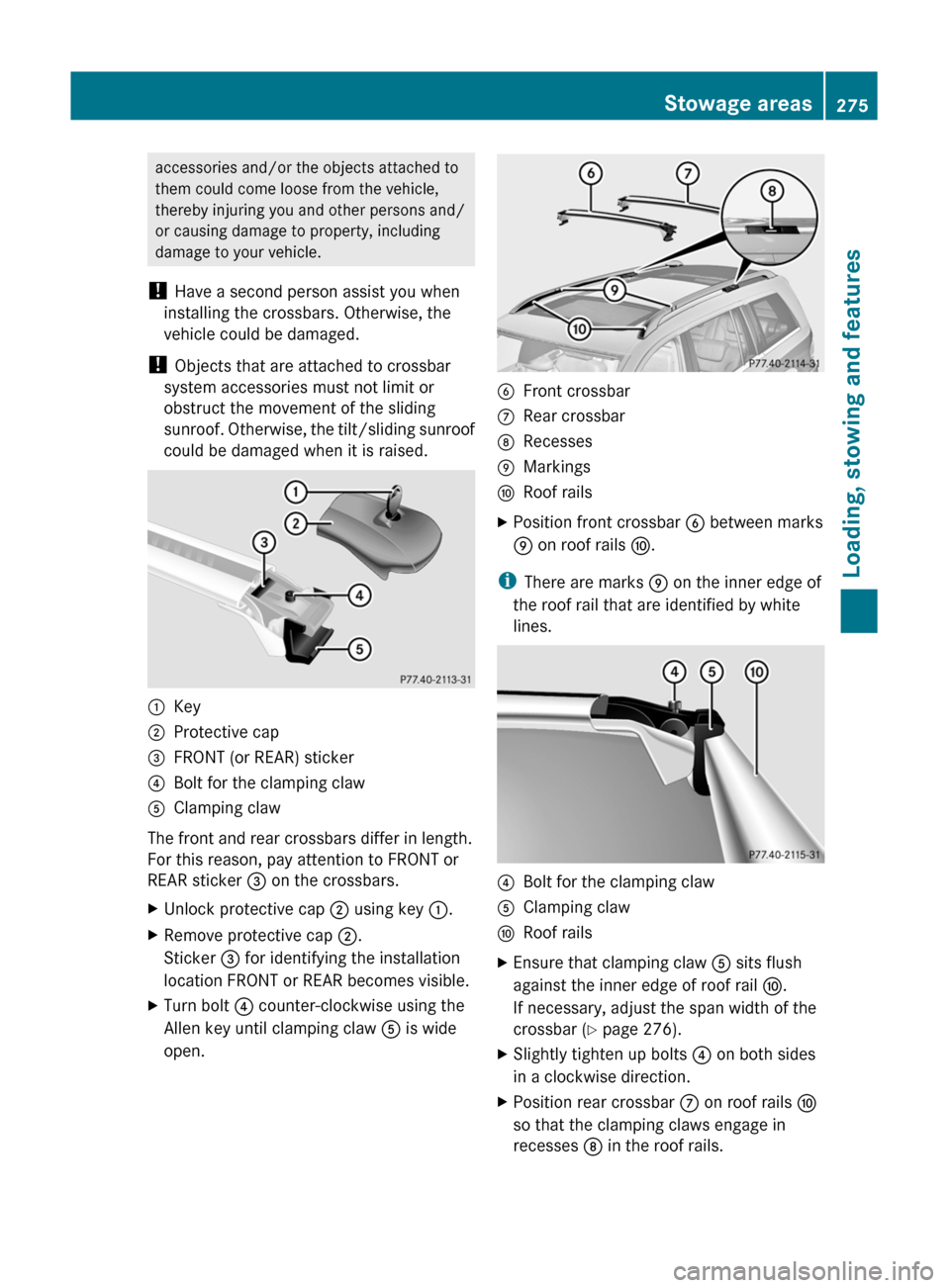
could be damaged when it is raised.:Key;Protective cap=FRONT (or REAR) sticker?Bolt for the clamping clawAClamping claw
The front and rear crossbars differ in length.
For this reason, pay attention to FRONT or
REAR sticker = on the crossbars.
XUnlock protective cap ; using key :.XRemove protective cap ;.
Sticker = for identifying the installation
location FRONT or REAR becomes visible.XTurn bolt ? counter-clockwise using the
Allen key until clamping claw A is wide
open.BFront crossbarCRear crossbarDRecessesEMarkingsFRoof railsXPosition front crossbar B between marks
E on roof rails F.
i
There are marks E on the inner edge of
the roof rail that are identified by white
lines.
?Bolt for the clamping clawAClamping clawFRoof railsXEnsure that clamping claw A sits flush
against the inner edge of roof rail F.
If necessary, adjust the span width of the
crossbar ( Y page 276).XSlightly tighten up bolts ? on both sides
in a clockwise direction.XPosition rear crossbar C on roof rails F
so that the clamping claws engage in
recesses D in the roof rails.Stowage areas275Loading, stowing and featuresBA 164.8 USA, CA Edition B 2011; 1; 2, en-USd2sboikeVersion: 3.0.3.52010-04-21T15:08:44+02:00 - Seite 275Z
Page 322 of 376
Do not tighten the wheel bolts when the
vehicle is raised. Otherwise, the vehicle could
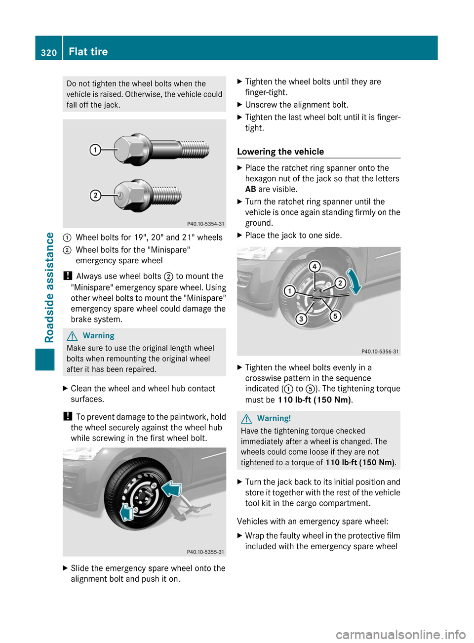
fall off the jack.1Wheel bolts for 19", 20" and 21" wheels2Wheel bolts for the "Minispare"
emergency spare wheel
! Always use wheel bolts ; to mount the
"Minispare" emergency spare wheel. Using
other wheel bolts to mount the "Minispare"
emergency spare wheel could damage the
brake system.
GWarning
Make sure to use the original length wheel
bolts when remounting the original wheel
after it has been repaired.
XClean the wheel and wheel hub contact
surfaces.
! To prevent damage to the paintwork, hold
the wheel securely against the wheel hub
while screwing in the first wheel bolt.
XSlide the emergency spare wheel onto the
alignment bolt and push it on.XTighten the wheel bolts until they are
finger-tight.XUnscrew the alignment bolt.XTighten the last wheel bolt until it is finger-
tight.
Lowering the vehicle
XPlace the ratchet ring spanner onto the
hexagon nut of the jack so that the letters
AB are visible.XTurn the ratchet ring spanner until the
vehicle is once again standing firmly on the
ground.XPlace the jack to one side.XTighten the wheel bolts evenly in a
crosswise pattern in the sequence
indicated ( : to A). The tightening torque
must be 110 lb-ft (150 Nm) .GWarning!
Have the tightening torque checked
immediately after a wheel is changed. The
wheels could come loose if they are not
tightened to a torque of 110 lb-ft (150 Nm).
XTurn the jack back to its initial position and
store it together with the rest of the vehicle
tool kit in the cargo compartment.
Vehicles with an emergency spare wheel:
XWrap the faulty wheel in the protective film
included with the emergency spare wheel320Flat tireRoadside assistance
BA 164.8 USA, CA Edition B 2011; 1; 2, en-USd2sboikeVersion: 3.0.3.52010-04-21T15:08:44+02:00 - Seite 320
Page 324 of 376
kit at the factory. It is therefore
recommended that you additionally equip
your vehicle with the TIREFIT kit if you
mount tires that do not feature run-flat
properties, e.g. winter tires. You can obtain
a TIREFIT kit from an authorized Mercedes-
Benz Center, for example.
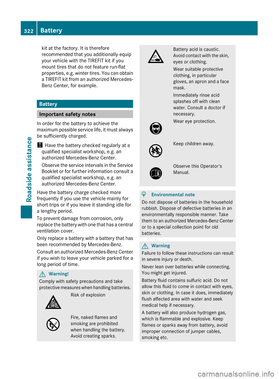
Battery
Important safety notes
In order for the battery to achieve the
maximum possible service life, it must always
be sufficiently charged.
! Have the battery checked regularly at a
qualified specialist workshop, e.g. an
authorized Mercedes-Benz Center.
Observe the service intervals in the Service
Booklet or for further information consult a
qualified specialist workshop, e.g. an
authorized Mercedes-Benz Center.
Have the battery charge checked more
frequently if you use the vehicle mainly for
short trips or if you leave it standing idle for
a lengthy period.
To prevent damage from corrosion, only
replace the battery with one that has a central
ventilation cover.
Only replace a battery with a battery that has
been recommended by Mercedes-Benz.
Consult an authorized Mercedes-Benz Center
if you wish to leave your vehicle parked for a
long period of time.
GWarning!
Comply with safety precautions and take
protective measures when handling batteries.
Risk of explosionFire, naked flames and
smoking are prohibited
when handling the battery.
Avoid creating sparks.
Battery acid is caustic.
Avoid contact with the skin,
eyes or clothing.
Wear suitable protective
clothing, in particular
gloves, an apron and a face
mask.
Immediately rinse acid
splashes off with clean
water. Consult a doctor if
necessary.
Wear eye protection.Keep children away.Observe this Operator's
Manual.
HEnvironmental note
Do not dispose of batteries in the household
rubbish. Dispose of defective batteries in an
environmentally responsible manner. Take
them to an authorized Mercedes-Benz Center
or to a special collection point for old
batteries.
GWarning
Failure to follow these instructions can result
in severe injury or death.
Never lean over batteries while connecting.
You might get injured.
Battery fluid contains sulfuric acid. Do not
allow this fluid to come in contact with eyes,
skin or clothing. In case it does, immediately
flush affected area with water and seek
medical help if necessary.
A battery will also produce hydrogen gas,
which is flammable and explosive. Keep
flames or sparks away from battery, avoid
improper connection of jumper cables,
smoking etc.
322BatteryRoadside assistance
BA 164.8 USA, CA Edition B 2011; 1; 2, en-USd2sboikeVersion: 3.0.3.52010-04-21T15:08:44+02:00 - Seite 322
Page 327 of 376
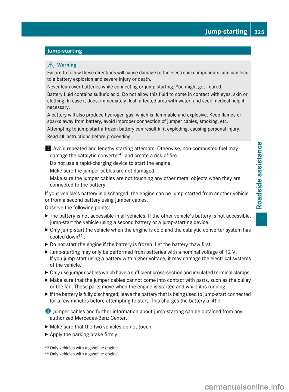
Jump-startingGWarning
Failure to follow these directions will cause damage to the electronic components, and can lead
to a battery explosion and severe injury or death.
Never lean over batteries while connecting or jump starting. You might get injured.
Battery fluid contains sulfuric acid. Do not allow this fluid to come in contact with eyes, skin or
clothing. In case it does, immediately flush affected area with water, and seek medical help if
necessary.
A battery will also produce hydrogen gas, which is flammable and explosive. Keep flames or
sparks away from battery, avoid improper connection of jumper cables, smoking, etc.
Attempting to jump start a frozen battery can result in it exploding, causing personal injury.
Read all instructions before proceeding.
! Avoid repeated and lengthy starting attempts. Otherwise, non-combusted fuel may
damage the catalytic converter 43
and create a risk of fire.
Do not use a rapid-charging device to start the engine.
Make sure the jumper cables are not damaged.
Make sure the jumper cables are not touching any other metal objects when they are
connected to the battery.
If your vehicle's battery is discharged, the engine can be jump-started from another vehicle
or from a second battery using jumper cables.
Observe the following points:
XThe battery is not accessible in all vehicles. If the other vehicle's battery is not accessible,
jump-start the vehicle using a second battery or a jump-starting device.XOnly jump-start the vehicle when the engine is cold and the catalytic converter system has
cooled down 44
.XDo not start the engine if the battery is frozen. Let the battery thaw first.XJump-starting may only be performed from batteries with a nominal voltage of 12 V.
If you jump-start using a battery with higher voltage, it may damage the electrical systems
of the vehicle.XOnly use jumper cables which have a sufficient cross-section and insulated terminal clamps.XMake sure that the jumper cables cannot come into contact with parts, such as the pulley
or the fan. These parts move when the engine is started and while it is running.XIf the battery is fully discharged, leave the battery that is being used to jump-start connected
for a few minutes before attempting to start. This charges the battery a little.
i Jumper cables and further information about jump-starting can be obtained from any
authorized Mercedes-Benz Center.
XMake sure that the two vehicles do not touch.XApply the parking brake firmly.43 Only vehicles with a gasoline engine.
44 Only vehicles with a gasoline engine.Jump-starting325Roadside assistanceBA 164.8 USA, CA Edition B 2011; 1; 2, en-USd2sboikeVersion: 3.0.3.52010-04-21T15:08:44+02:00 - Seite 325Z
Page 373 of 376
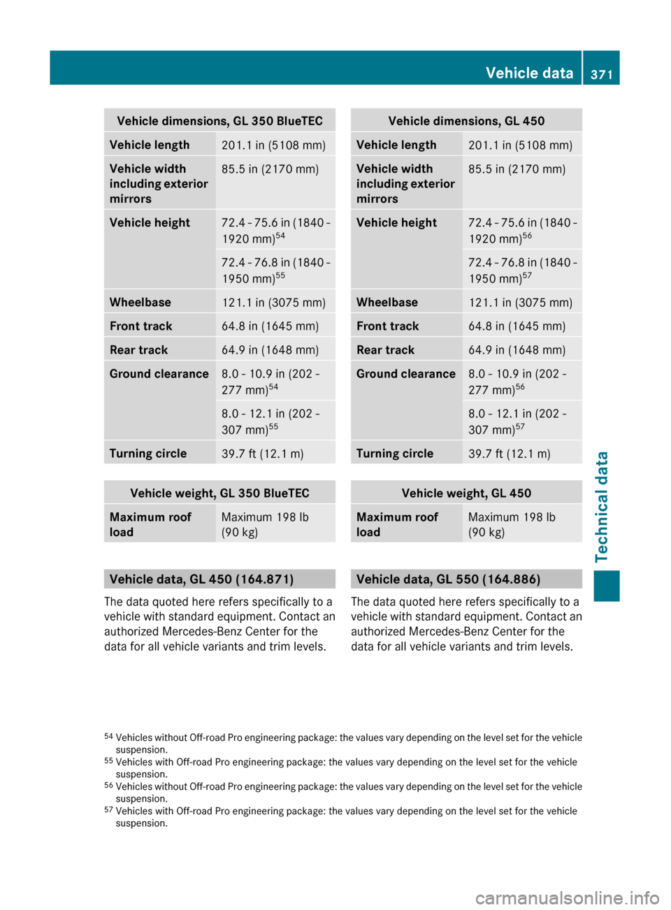
Vehicle dimensions, GL 350 BlueTECVehicle length201.1 in (5108 mm)Vehicle width
including exterior
mirrors85.5 in (2170 mm)Vehicle height72.4 - 75.6 in (1840 -
1920 mm) 5472.4 - 76.8 in (1840 -
1950 mm) 55Wheelbase121.1 in (3075 mm)Front track64.8 in (1645 mm)Rear track64.9 in (1648 mm)Ground clearance8.0 - 10.9 in (202 -
277 mm) 548.0 - 12.1 in (202 -
307 mm) 55Turning circle39.7 ft (12.1 m)Vehicle weight, GL 350 BlueTECMaximum roof
loadMaximum 198 lb
(90 kg)
Vehicle data, GL 450 (164.871)
The data quoted here refers specifically to a
vehicle with standard equipment. Contact an
authorized Mercedes-Benz Center for the
data for all vehicle variants and trim levels.
Vehicle dimensions, GL 450Vehicle length201.1 in (5108 mm)Vehicle width
including exterior
mirrors85.5 in (2170 mm)Vehicle height72.4 - 75.6 in (1840 -
1920 mm) 5672.4 - 76.8 in (1840 -
1950 mm) 57Wheelbase121.1 in (3075 mm)Front track64.8 in (1645 mm)Rear track64.9 in (1648 mm)Ground clearance8.0 - 10.9 in (202 -
277 mm) 568.0 - 12.1 in (202 -
307 mm) 57Turning circle39.7 ft (12.1 m)Vehicle weight, GL 450Maximum roof
loadMaximum 198 lb
(90 kg)
Vehicle data, GL 550 (164.886)
The data quoted here refers specifically to a
vehicle with standard equipment. Contact an
authorized Mercedes-Benz Center for the
data for all vehicle variants and trim levels.
54 Vehicles without Off-road Pro engineering package: the values vary depending on the level set for the vehicle
suspension.
55 Vehicles with Off-road Pro engineering package: the values vary depending on the level set for the vehicle
suspension.
56 Vehicles without Off-road Pro engineering package: the values vary depending on the level set for the vehicle
suspension.
57 Vehicles with Off-road Pro engineering package: the values vary depending on the level set for the vehicle
suspension.Vehicle data371Technical dataBA 164.8 USA, CA Edition B 2011; 1; 2, en-USd2sboikeVersion: 3.0.3.52010-04-21T15:08:44+02:00 - Seite 371Z
Page 374 of 376
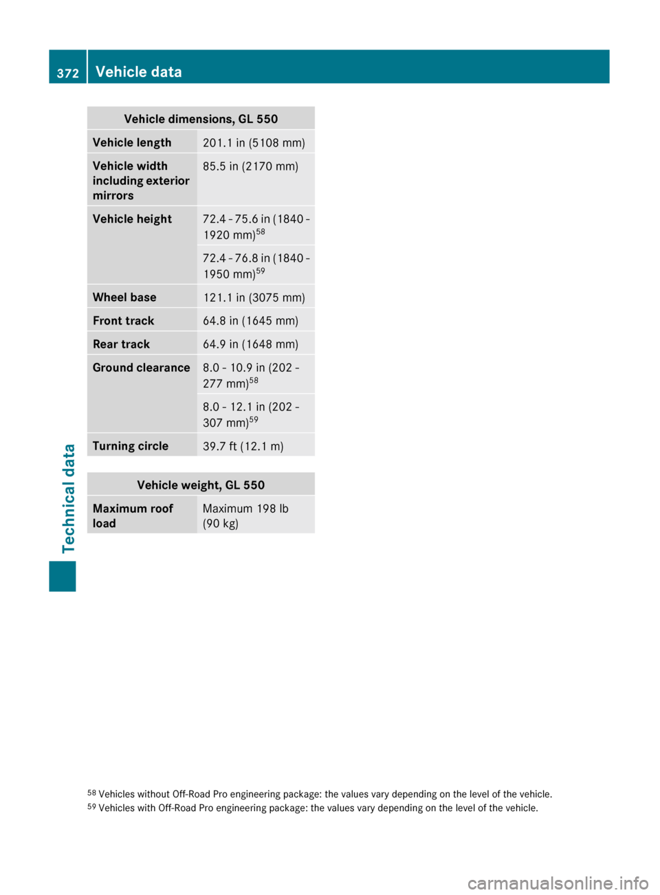
Vehicle dimensions, GL 550Vehicle length201.1 in (5108 mm)Vehicle width
including exterior
mirrors85.5 in (2170 mm)Vehicle height72.4 - 75.6 in (1840 -
1920 mm) 5872.4 - 76.8 in (1840 -
1950 mm) 59Wheel base121.1 in (3075 mm)Front track64.8 in (1645 mm)Rear track64.9 in (1648 mm)Ground clearance8.0 - 10.9 in (202 -
277 mm) 588.0 - 12.1 in (202 -
307 mm) 59Turning circle39.7 ft (12.1 m)Vehicle weight, GL 550Maximum roof
loadMaximum 198 lb
(90 kg)58 Vehicles without Off-Road Pro engineering package: the values vary depending on the level of the vehicle.
59 Vehicles with Off-Road Pro engineering package: the values vary depending on the level of the vehicle.372Vehicle dataTechnical data
BA 164.8 USA, CA Edition B 2011; 1; 2, en-USd2sboikeVersion: 3.0.3.52010-04-21T15:08:44+02:00 - Seite 372